Page 533 of 1413
Clutch
lllustrated Index (cont'd)
2ND/4TH CLUTCH
SNAP RING
SPRING RETAINER
RETURN SPRING
CLUTCH END PLATE
4TH CLUTCH DRUM
CLUTCH PLATESStanda.d thickness:2.00 mm 10.079 in)
SNAP RING
CLUTCH DISCSStandard thickno3s:1.94 mm 10.076 in)
CLUTCH END PLATE
;;i;;; /
(/\
Y)
)
l
CLUTCH PISTON
CLUTCH PLATESStandard thickness:2.OO mm 10.079 inl
SPRING
RETURN SPRING
RETAINER
SNAP RING
CLUTCH DISCSStsndard ihickn€ss:1.94 mm 10.076 in)
CHECK VALVE
SNAP RING
14-142
Page 537 of 1413
Clutch
Reassembly
NOTE:
a Clean all psrts thoroughly in solvent or carburetorcleaner. and dry them with compressed air.a Blow out all passages.
a Lubricate all pans with ATF before .eassembly.
1. Inspect the check valve; if it's loose, replace theprston,
NOTE: Except 1st-hold clutch.
CHECK VAIVE
PISTON
14-146
3, Installthe piston in the clutch drum. Apply pressure
and rotate to ensure proper seating.
NOTE: Lubricate the piston O-ring with ATF beforeinstalling,
CAUTION: Do not pinch rh6 O-ring by installing th€piston with too much lorco.
CLUTCH DRUM
Installthe return spring and spring retainer. and po-
sition the snap ring on the retainer
4.
SNAP RING
SPRING RETAINER
RETURN SPRING
CLUTCH ORUM
Page 546 of 1413
Transmission
NOTE:
a Coat all parts with ATF.a Replace the parts below:. O-rings. Lock washers. Gaskets. Locknuts. Conical spring washers. Sealing washers
TOROUE: 12 N.m (1.2 kgt.m, 8.7 tbf.fr)
LOCK-UP VALVEEODY
OOWEL PINS, 2
COOLER CHECK VALVE
Reassembly
Bolts,4
DOWEL PINS. 2
MAIN VALVE
OIL FEED PIPE
/ LUBRTcAToR
, PLATE
fln /
| / /""n
v{*' e'f _\
_! 1.-...-]]
-. :-,.
OOWEL PINS, 2
orLFEEDPIPES
OIL FEED PIPES
ACCUMULATOB COVER
OIL FEED PIPE
Bolts,3
e
"o't
CONTROL
E SHAFT
LOCK WASHER
SERVO DETENTBASE
REGULATOR VALVEBODY
OIL FEED PIPES
SERVO BODY
SERVO SEPARATORPLATE
EoDY | . "1-
OIL PUMP DRIVEN
GEAR SHAFT
OIL PUMP DRIVEN GEAR
MAIN S€PARATORPLATE
SECONDARY VALVEBODY
DOWEL PINS, 2
SECONDARY SEPARATORPLATE
vaLVE spRtNGS \_(< \
ToRou E coN vE RTE n \-\.--CHECK VALVE ----.-. --'r -
Bolt
14-156
ATF MAGNET
Page 547 of 1413

2.
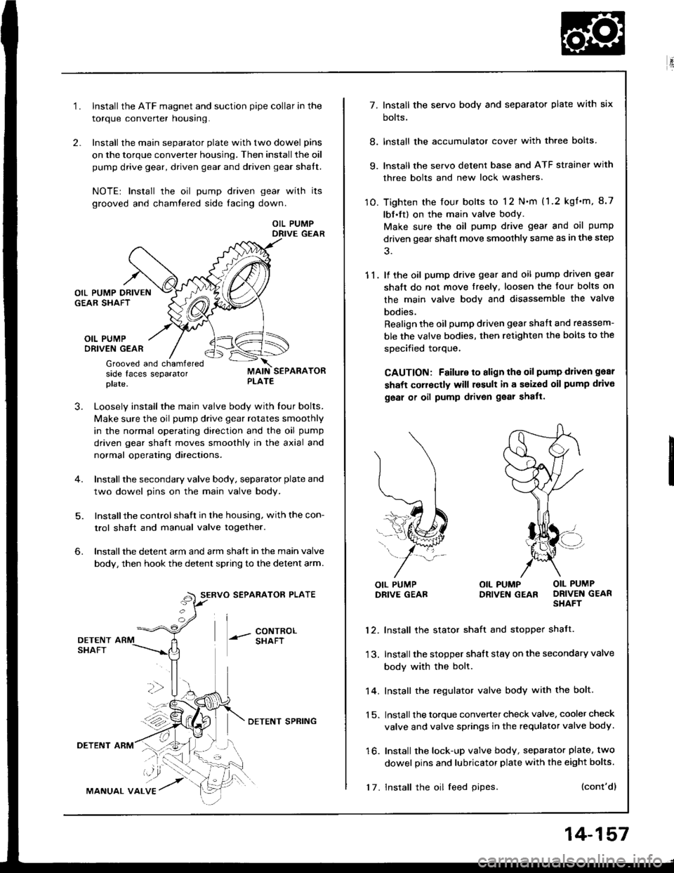
1.Install the ATF magnet and suction pipe collar in the
torque converter nousrng.
Install the main separator plate with two dowel pins
on the torque converter housing. Then install the oil
pump drive gear, driven gear and driven gear shalt.
NOTE| Install the oil pump driven gear with its
grooved and chamtered side facing down.
OIL PUMPDRIVE GEAR
OIL PUMPORIVEN GEAR
Grooved and chamferedside faces separatorplate.
J.Loosely install the main valve body with Iour bolts.
Make sure the oil pump drive gear rotates smoothly
in the normal operating direction and the oil pump
driven gear shaft moves smoothly in the axial and
normal operating directaons.
Install the secondary valve body, separator plate and
two dowel pins on the main valve body.
Installthe control shaft in the housing, with the con-
trol shatt and manual valve togelher.
Install the detent arm and arm shatt in the main valve
body, then hook the detent spring to the detent arm.
SERVO SEPARATOR PLATE
--- 8ixli"'
6.
36
DETENTSHAFT
DETENT ARM
MANUAL VALVE
DETENI SPRING
17. Install the oil feed pipes.
14-157
E'.:
7. Install the servo body and separator plate with six
bolts.
8. lnstall the accumulator cover with three bolts
9. lnstall the servo detent base and ATF strainer with
three bolts and new lock washers.
10. Tighten the four bolts to 12 N.m (1.2 kgf'm, 8.7
lbf.ft) on the main valve body.
Make sure the oil pump drive gear and oil pump
driven gear shaft move smoothly same as in the step
11. lf the oil pump drive gear and oil pump driven gear
shaft do not move freelY. loosen the four bolts on
the main valve body and disassemble the valve
bodies.
Realign the oil pump driven gear shaft and reassem-
ble the valve bodies, then retighten the bolts to the
specified torque,
CAUTION: Failure to align the oil pump d1iv6n gear
shaft corroctly will result in a seized oil pump drivo
geal of oil pump drivon gear shatt.
l\
(...l
=..�N
L,1ffi#
j-*/:
OIL PUMPDRIVE GEABOIL PUMP OIL PUMPDRIVEN GEAR DRIVEN GEARSHAFT
12. Install the stator shaft and stopper shatt.
13. Install the stopper shatt stay on the secondary valve
body with the bolt.
14. Install the regulator valve body with the bolt.
1 5. Install the torque converter check valve, cooler check
valve and valve springs in the requlator valve body.
16. Install the lock-up valve body, separator plate, two
dowel pins and lubricator plate with the eight bolts.
(cont'dl
Page 557 of 1413

20. Connect the vehicle speed sensor (VSS), mainshatt
speed sensor and counterchalt speed sensor con
nectors.
VEHICLE SPEED SEiISORCONNECTOR
21. Connect the lock-uD control solenoid valve connec-
tor and shift control solenoid valve connector. then
clamp the lock-up control solenoid harness with the
harness stay.
22. Connect the transmission ground cable.
LOCK-UP CONTROLSOLENOID VALVE HARNESS STAY
23. Connect the starter cable to the starter motor, and
install the cable holder.
NOTE: When installing the starter motor cable,
make sure that the crimped side of the ring terminal
is facing out (see section 23).
CABLEHOLDER
6x 1.0 mm'12 N.m (1.2 kgf'm,8.7 lbt.tl)
24.
N.mlO.9 ksr.m, 7 tbr-rtt
STARTER CAELE
Install the air cleaner housing assembly and intake
arr oucl.
AIR CLEANER HOUSINGASSEMBLYINTAKE AIRDUCT
25.
26.
24.
29.
30.
Retill the transmission with ATF(see page '14-93).
Connect the battery positive ( + ) and negative ( - )
cables to the battery.
Start the engine. Set the parking brake, and shift the
transmission through all gears three times.
Check shitr cable adjustment as described on page
14-171 .
Check that front wheel alignment (see section 18).
Let the engine reach operating temperature (the cool-
ing tan comes on) with the transmission in S or @position, then turn it off and check the fluid level.
31. Road test as described on page 14-9o and 91.
14-167
Page 558 of 1413

Transmission
Cooler Flushing
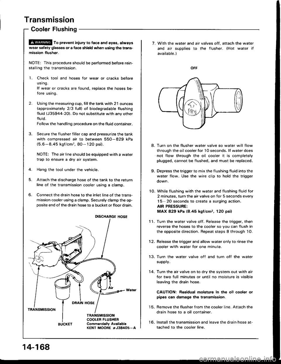
S!@ ro prevent iniury to tace and eyes, always
wear safety glas$es or a tace shield when using the trans-
mission flusher.
NOTE: This procedure should be performed before rein-
stalling the transmission.
1. Check tool and hoses for wear or cracks before
using.
lf wear or cracks are found, replace the hoses be-
fore using.
2. Using the measuring cup, tillthe tank with 21 ounces
{approximately 213 lulll of biodegradable tlushing
fluid (J35944-20). Do not substitute with any other
fluid.
Follow rhe handling procedure on the fluid container.
Secure the tlusher filler cap and pressurize the tank
with compressed air to between 550-829 kPa(5.6-8.45 kgt/cm,, 80- 120 psi),
NOTE: The air line should be equipped with a water
trap to ensure a dry air system.
Hang the tool under the vehicle.
Attach the discharge hose of the tank to the return
line of the transmission cooler using a clamp.
Connect the drain hose to the inlet line of the trans-
mission cooler using a clamp. Securely clamp the op-posite end of the drain hose to a bucket or floor drain.
6.
DRAIN HOSE
TRANSMISSION
TRANSMISSIONCOOLER FLUSHEBCommorcially AvailabloKENT MOORE #J38405_A
DISCHARGE HOSE
14-168
BUCKET
7. With the water and air valves off. attach the water
and air supplies to the flusher. (Hot water it
available.)
OFF
8. Turn on the flusher water valve so water will tlow
through the oil cooler for 1O seconds. lf water does
not flow through the oil cooler it is completely
plugged, cannot be flushed, and must be replaced.
9. Depress the trigger to mix the tlushing lluid into the
water tlow. Use the wire clip to hold the trigger
oown.
10. While flushing with the water and flushing fluid for
2 minutes. turn the air valve on for 5 seconds every
15-20 seconds to create a surging action.
AIR PRESSURE:
MAX 829 kPa (8.45 kgt/cm,, 12O psi)
1 1. Turn the water valve off. Release the trigger, then
reverse the hoses to the cooler so you can flush in
the opposite direction. Repeat steps 8 through 1O.
12. Release the trigger and allow water only to rinse the
cooler with water for one minute.
13. Turn the water valve off and turn off the water
supply.
14. Turn the air valve on to dry the system out with air
for two full minutes or until no moisture is visible
leaving the drain hose.
CAUTION: Residual moisture in the oil cooler 01
pipes can damage the transmission.
15. Remove the flusher trom the cooler line. Attach the
drain hose 10 a oil container.
16. lnstallthe transmission and leave the drain hose at-
tached to the cooler line.
Page 609 of 1413

I
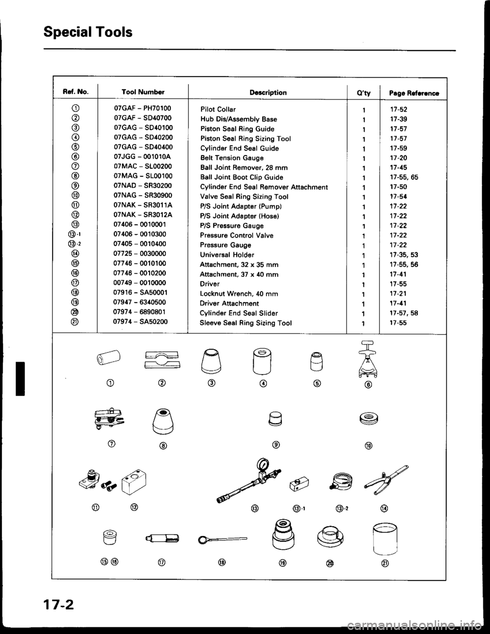
Rcf. No. I Tool Numb€lDcscriptionO'ty I P!9. Relrrrncc
o
@
@(t
@
@
o
@
@
@
@
@
@
@.r
@-2
@
@
@
@
@
@
@
@
07GAF - PH70100
07GAF - SD40700
07GAG - SD40100
07GAG - SD40200
07GAG - SD40400
07JGG - 0010104
07MAC - 5100200
07MAG - 5100100
07NAD - SR30200
07NAG - SR30900
OTNAK - SR3O11A
OTNAK - SR3O12A
07406 - 0010001
07406 - 0010300
07405 - 0010400
07725 - 0030000
07746 - 0010100
07746 - 0010200
007i$ - 0010000
07916 - SA50001
07947 - 6340500
07974 - 6890801
0797,1 - SA50200
Pilot Collar
Hub DivAssembly Base
Piston Seal Ring Guide
Piston Seal Ring Sizing Tool
Cylinde. End Seal cuide
Belt Tension Gauge
Ball Joint Remover, 28 mm
Ball Joint Boot Clip Guide
Cylinder End Seal Remover Attachment
Valve Ssal Ring Sizing Tool
P/S Joint Adapter (Pump)
P/S Joint Adapter (Hos6)
P/S Pressure Gsuge
Pressure Control Valve
Pressure Gauge
Universal Holder
Attachment, 32 x 35 mm
Attachment, 37 x 40 mm
Driver
Locknut Wrench, i[0 mm
Driver Anachment
Cylinder End Seal Slider
Sleeve Sesl Ring Sizing Tool
1
I
1
1
1
1
1
1
1'I
1
1
1
1
1
1'l
1
I
1
1
1
1
'17 -52
17-39
17 -57
17 -57
17-EO
17 -20't7 -15
17-50
17-5{
17 -22
17 -22't1-22
17 -22
17-35, 53
17-55, 56
17 -1'l
t7-55
17 -2'l
17 -11
17-57,58
17-55
aL2
o
re
F--,'---l
@
g
t.-,
@
q
o
etl
TJ
@
a\,
@
e
U
\v
o
I
@
,h z6)
@@
@
@-r
6
w
@,2
^dN
v
@
@
16)
Y
@@
lx:__E
@
@:
@@
17-2
Page 611 of 1413
System Description
Fluid Flow Diagram
The system is a compact rotary-valvs-type power stssring, connocted to the st€oring gearbox. Th6 fluid pressure is pro-vided by a vane-type pump which is driven by the engine crank pulley. The amount of fluid and pressurs is regulsted bythe flow control valve built into ths pump, The fluid prssaurs from th6 pump is dolivsred to tho valve unit sround the pin-ion of the steering g€arbox. The vslv€ inside the valvs unit controls the hydraulic prossur€ End changos the direction otthe flow. The fluid then flows to the power cylinder, where rack thrust is gen6rat6d. Fluid returning from th6 powsr cylin-der flows back to the .eservoir, where the fluid is 'filtered" and supplied to the pump Egain.
17-4