1994 ACURA INTEGRA Valve
[x] Cancel search: ValvePage 666 of 1413
41.
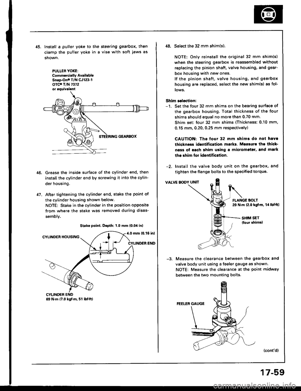
Install a puller yoke to the steering gearbox, then
clamp the puller yoke in a vise with soft jaws as
shown.
PULLER YOXE:Commcrcirlly AvrihbloSn.p-Ono T/N Cr123-lorco T/N 7372or aquivrlani
Grease the inside surface of the cylinder end, then
install the cylinder end by screwing it into the cylin-
der housing.
After tightening the cylinder end, stake the point of
the cylinder housing shown below.
NOTE: Stake in the cylinder in the position opposite
from where the stake was removed during disas-
semblv.
Strke point, D.pth: 1.0 mm (0.04 inl
4.0 mm 10.15 inlCYLINDER HOUSING
CYLINDER END
CYLINOER69 N.m 17.0 kgf.m, 51 lbtft)
,t8. Select the 32 mm shim(s).
NOTE: Only reinstall the original 32 mm shim(s)
when the steering gearbox is reassembled without
replacing the pinion shaft, valve housing, and gear-
box housing with new ones.
lf the pinion shaft, valve housing, and gearbox
housing are replaced, select the new shim{s) as fol-
rows.
Shim r€lection:-'1. Set the four 32 mm shims on the b€aring surface of
the gearbox housing. Total thickness of the four
shims should eoual no more than 0.70 mm.
Shim set: tour 32 mm shims (Thickness: 0.10 mm,
0.15 mm, 0.20, 0.25 mm respectivelyl
CAUTION: The tour 32 mm shimr do not hlva
thlckn$s idcntitication mukt. Mo!3ur. tho thicl-
oa33 of rach 3him using a miclomctrl, and mlrk
tho shim lor id6ntific8tion.
-2. Install the valve body unit on the gearbox, and
tighten the flange bolts to the specitied torque
VALVE BODY UNIT
FLANGE BOLT20 N.m {2.o kgtm, 14lbt'ftl
SHIM SET{foul thim.)
Measure the clearance between the gearbox and
valve body unit using a feeler gauge as shown.
NOTE: Measure the clearance at the point midway
between the two mounting bolts.
(cont'd)
17-59
Page 667 of 1413
Steering Gearbox
Reassembly lcont'd)
-4. Determine the requifed thickness of the 32 mm
shims by subtracting the clearance obtained in thestep -3 from the total thickness of the four shims.(Total thickness of the 4 shims) - (Clearance) =
Required thickness of the shims
NOTE: Select the shims so that th6 total thicknessis close to, but less than the required thickness.
Exampls:
Measu.ement is 0.28 mm (0.011 in):
0.70 - 0.28 = 0.42 mm (0.028 - 0.011 = 0.0't7 in)
The selected shims should be 0.25 mm (O.O1O in) and0.15 mm (0.005 in) in thickness.
lf the required shim thickness is 0.lO mm or less, no
shims are necessary.
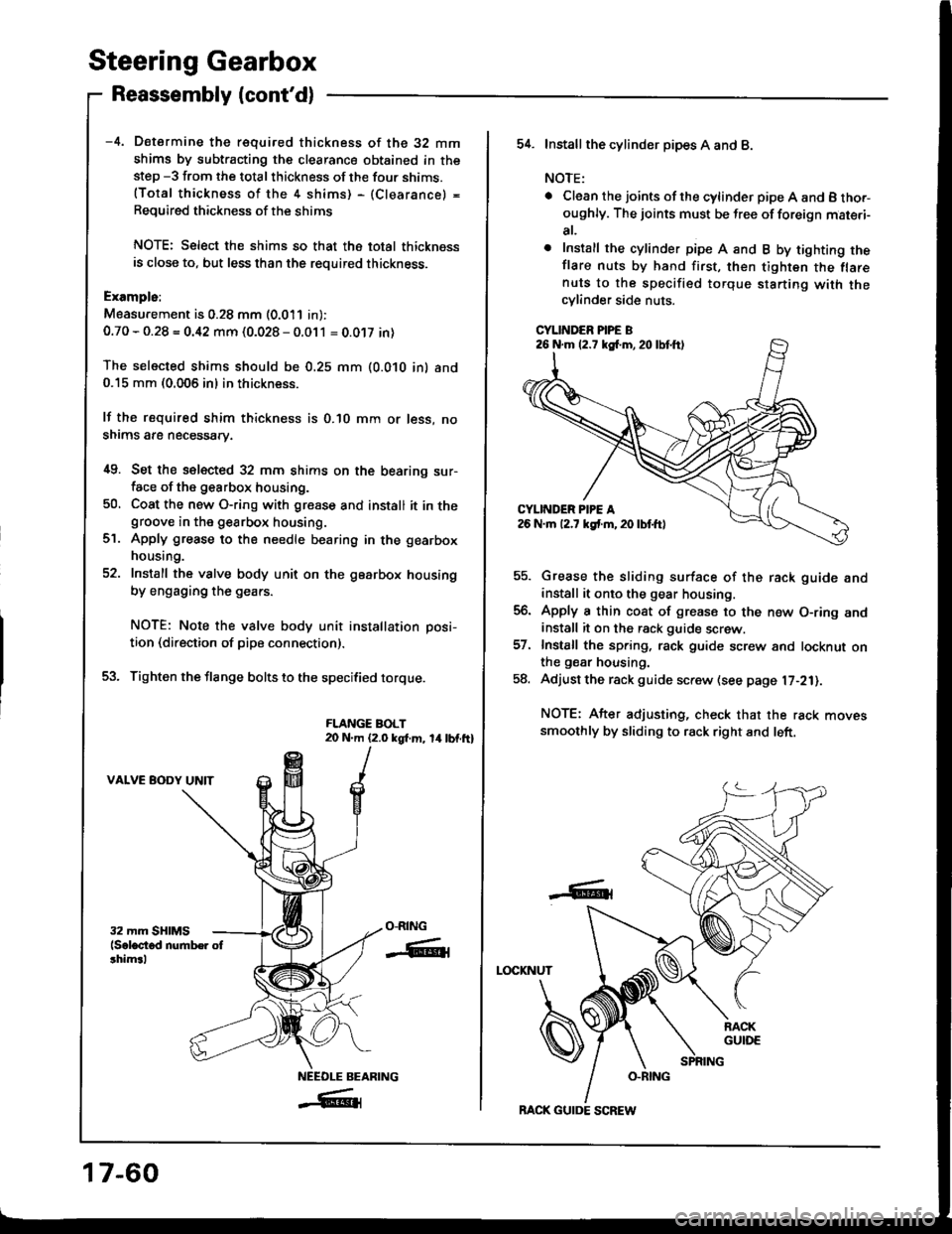
i[9. Set the selected 32 mm shims on the bearing sur-face of the g€arbox housing.
50, Coat the new O-ring with gresse and install it in thegroove in the gearbox housing.
Apply grease to the needle bearing in the gearbox
housing.
Install the valve body unit on the gearbox housing
by engaging the gears.
NOTE: Note the valve body unit installation posi-
tion (direction of pipe connection).
Tighten the flange bolts to the specified torque.
FLANGE BOLT20 N.m (2.0 kgt m, 14lbf.ft)
VALVE BODY UNIT
ct.
O-RING
-ffiti
NEEOLE BEARING
_#{
17-60
BACK GUIDE SCREW
54. Installthe cylind6r pipes A and B.
NOTE:
. Clean the joints ofthe cylinder pipe A and B tho.-oughly. The joints must be free of foreign mat€.i-
at,
o Install the cylinder pipe A and B by tighting theflare nuts by hand first, then tighten the flarenuts to the specified torque starting with thecylinder side nuts.
CYLINDER PIPE B
Grease the sliding surface of the rack guide andinstall it onto the gear housing.
Apply a thin coat of grease to the n€w O-ring andinstall it on the rack guide screw.
Install the spring, rack guide screw and locknut onthe gear housing.
Adjust the rack guide screw (see page l7-21).
NOTE: After adjusting, check that the rack movessmoothly by sliding to rack right and left.
LOCKNUT
-6t
26 N.m (2.7 kg{.m,20lbtft)
Page 670 of 1413
lnstallation
CAUTION; BG Glrc{ul not io bcnd or drm8go tho piping
whcn in3tllling tho gea.box.
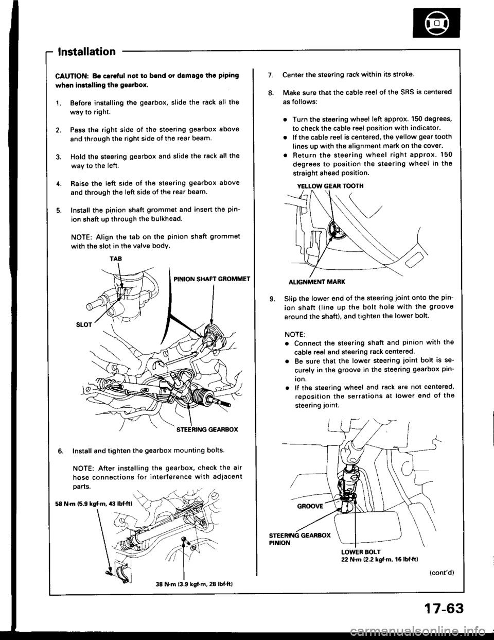
1. Before installing the gearbox, slide the rack all the
way to right.
2. Pass the right side of the steering gearbox above
and through the right side of the rear beam.
3. Hold the steering gearbox and slide the rack all the
wav to the left.
4. Raise the left side of the steering gearbox above
and through the left side of the rear beam.
5. Install the pinion shaft grommet and insert the pin-
ion shaft up through the bulkhead.
NOTE: Align the tab on the pinion shaft grommet
with the slot in the valve bodv.
6. Install and tighten the gearbox mounting bolts.
NOTE: After installing the gearbox, check the air
hose connactions for interference with adjacent
pans.
58 N.m 15.9 kg[.m, $ lbl.ftl
TAA
38 N m 13.9 kgl.m, 28 lbt.ftl
17-63
YELLOW GEAR TOOTH
7.Center the steering rack within its stroke.
Make sure that the cable reel of the SRS is centered
as follows:
. Turn the steering wheel left approx. 150 degrees,
to check the cable reel position with indicator.
. lfthe cable reel is centered. the yellow gear tooth
lines up with the alignment mark on the cover.
. Return the steering wheel right approx. 150
degrees to position the steering wheel in the
straight ahead position.
ALIGNMEi'IT MARK
Slip the lower end of the steering joint onto the pin-
ion shaft (line up the bolt hole with the groove
around the shaft), and tighten the lower bolt.
NOTE:
. Connect the steering shaft and pinion with the
cable reel and steering rack centered.
. Be sure that the lower steering ioint bolt is se-
curely in the groove in the steering gearbox pin-
ion.
. lf the steering wheel and rack are not centeted,
reposition the serralions at lower end of the
steering joint.
(cont'dl
22 N.m 12.2 kgi.m, 16lbf.ftlLOWER BOLT
Page 671 of 1413

Steering Gearbox
Installation (cont'd)
10. Install the steering joint cover with the clamps andcliDs.
STEERING JOINT COVER
11. Connect the fluid lines to the valve bodv unit.
CLIP
RETURN HOSE
17-64
38 N.m 13.9 kg{.m, 28 lbf.ft)
12. Install the rear beam brace rod and return pipe
clamp on the rear beam.
NOTE: Install the rear beam brace toward thereturn pipe clamp.
13. Install the three way catalytic converter with thenew gaskets and new self-locking nuts, and connectthe heated oxygen sensor (H02S) connector,
HEATED OXYGEN SENSOR CONNECTOF
SELF.LOCKING NUT33 N.m 13.4
SELF.LOCKING NUT22 N.m (2.2 kgt m, 16 lbt.ftl
14. Connect the shift linkage (M/T model: see section
13, A/T model: see section 14).
Page 956 of 1413
Motor, Drain Tube and Frame Replacement
CAUTION: Be carotul not to damago th€ seats, dash-
board and other int6rior trim,
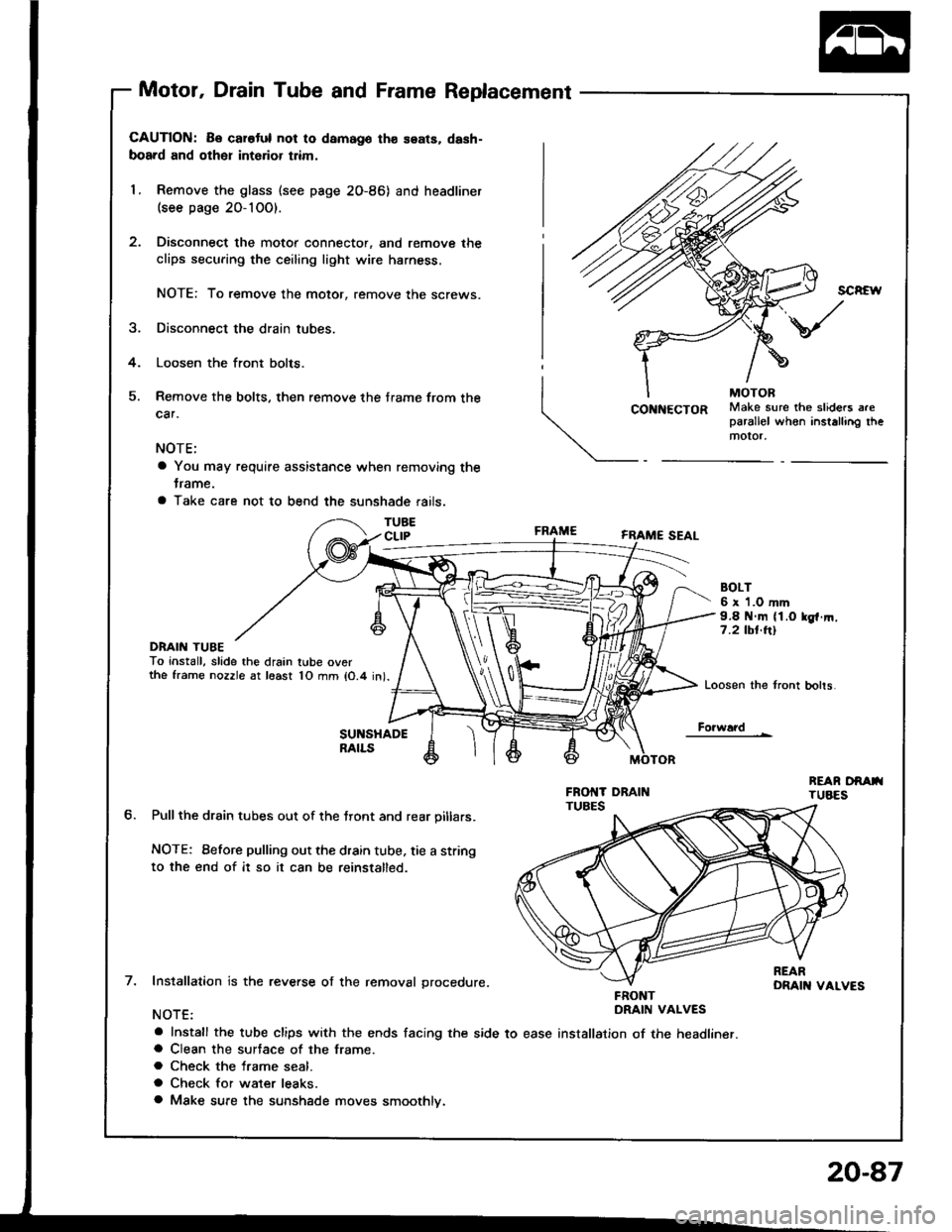
1. Remove the glass (see page 2O-86) and headliner(see page 20-10O).
Disconnect the motor connector, and remove the
clips securing the ceiling light wire harness.
NOTE: To remove the motor, remove the screws.
Disconnect the drain tubes.
Loosen the front bolts.
Remove the bolts, then remove the trame from the
car.
NOTE:
a You may require assistance when removing the
trame.
a Take care not to bend the sunshade rails.
TUBECLIP
DRAIN TUBETo install, slade the drain tube ov6rthe frame nozzle at least 10 mm lO.4 in).
SUNSHADERAILS
Pullthe drain tubes out of the tront and rear oillars.
NOTE: Before pulling out the drain tube, tie a string
to the end of it so it can be reinstalled.
Installation is the reverse of the removal grocedure.
NOTE:
a Install the tube clips with the ends facing the side to easea Clean the surtace of the frame.
a Check the frame seal.
a Check for water leaks.
a Make sure the sunshade moves smoothlv.
SCREW
4.
\/
Make sure the sliders areparallel when installing themotor,
CONNECTOR
FRAME
BOLT6 x 1.0 mm9.8 N.m (1.O lg{.rn.7.2 tbt.ttl
Loosen the tront bohs
Fo?w!?d
tt.
FRONTDRAIN VALVES
installation of the headliner.
20-87
Page 1038 of 1413
Heater
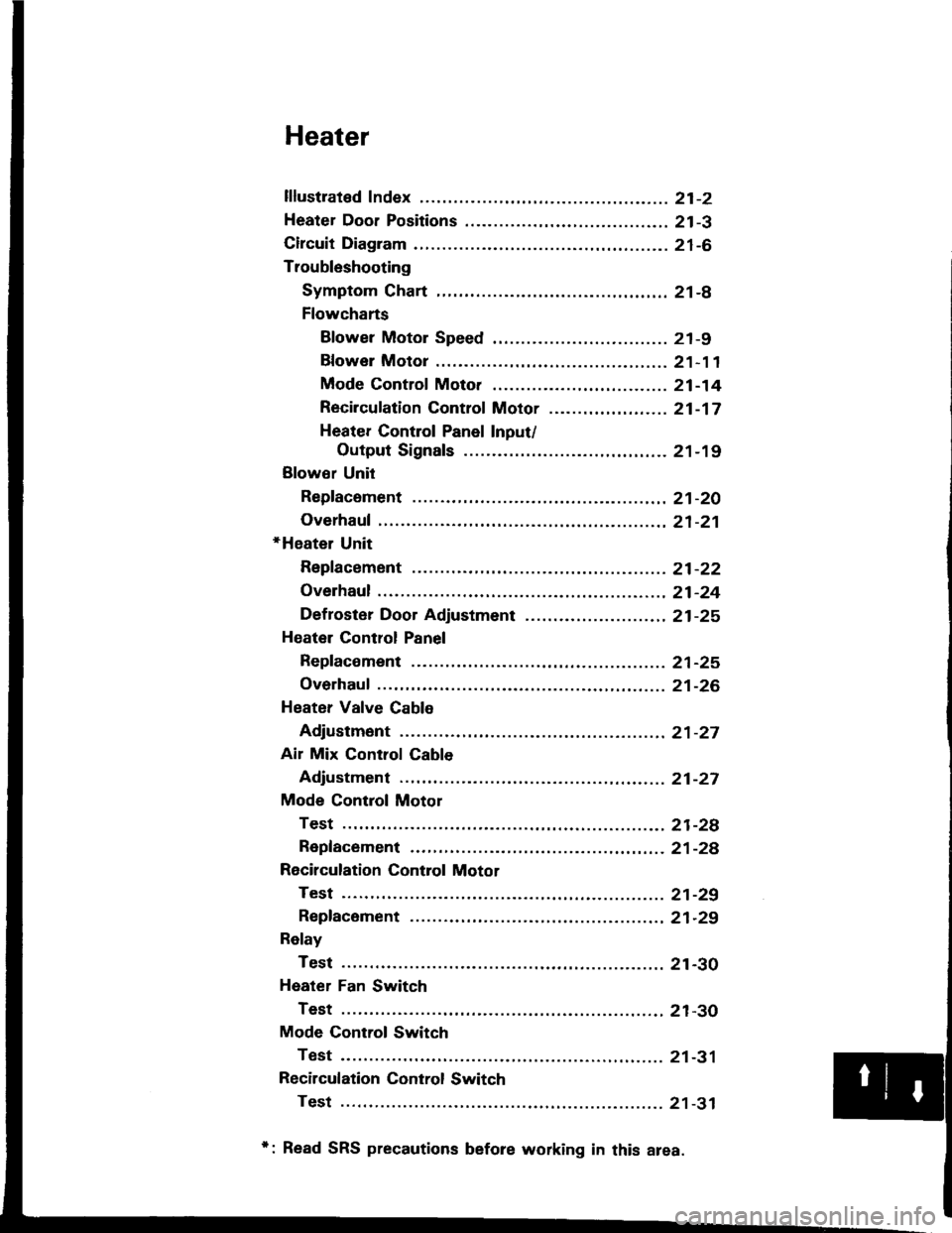
lflustrated Index ............. .........21-2
Heater Door Positions .........,..,. 21-3
Circuit Diagram ....................... 21-6
Troubleshooting
Symptom Chart ............. ......21-8
Flowcharts
Blower Motor Speed ............................... 21 -9
Bfower Motor .........,..,,,,,.. 21-11
Mode Control Moto. ............ ................... 21 -14
Recircufation Control Motor ......,...,.,,,.,.... 21 -17
Heater Control Panel Input/
Output Signals ..............21-19
Blower Unit
Repfacoment ....................... 21-20
Overhaul .......21-21
+Heater Unit
Repfacement ....................... 21-22
Overhaul .......21-24
Def roster Door Adjustment ...,............. ......,, 21 -25
Heatel Control Panel
Repfacoment ....................... 21-25
Overhaul .......21-26
Heater Valve Cable
Adjustment ...21-27
Air Mix Control Cable
Adjustment ... 21-27
Mode Control Motol
Test .............. ..................... 21-2e
Repfacement ..,..............,,,,.. 21-28
Recirculation Control Motor
Test .............. ..................... 21-29
Repfacement ....................... 21-29
Relay
Test .............. ..................... 21-30
Heater Fan Switch
Test .............. ..................... 21-30
Mode Control Switch
Test .............. ..................... 21-31
Recilculation Control Switch
Test .............. ..................... 21 -31
*: Read SRS precautions before working in this area.
Page 1045 of 1413
Troubleshooting
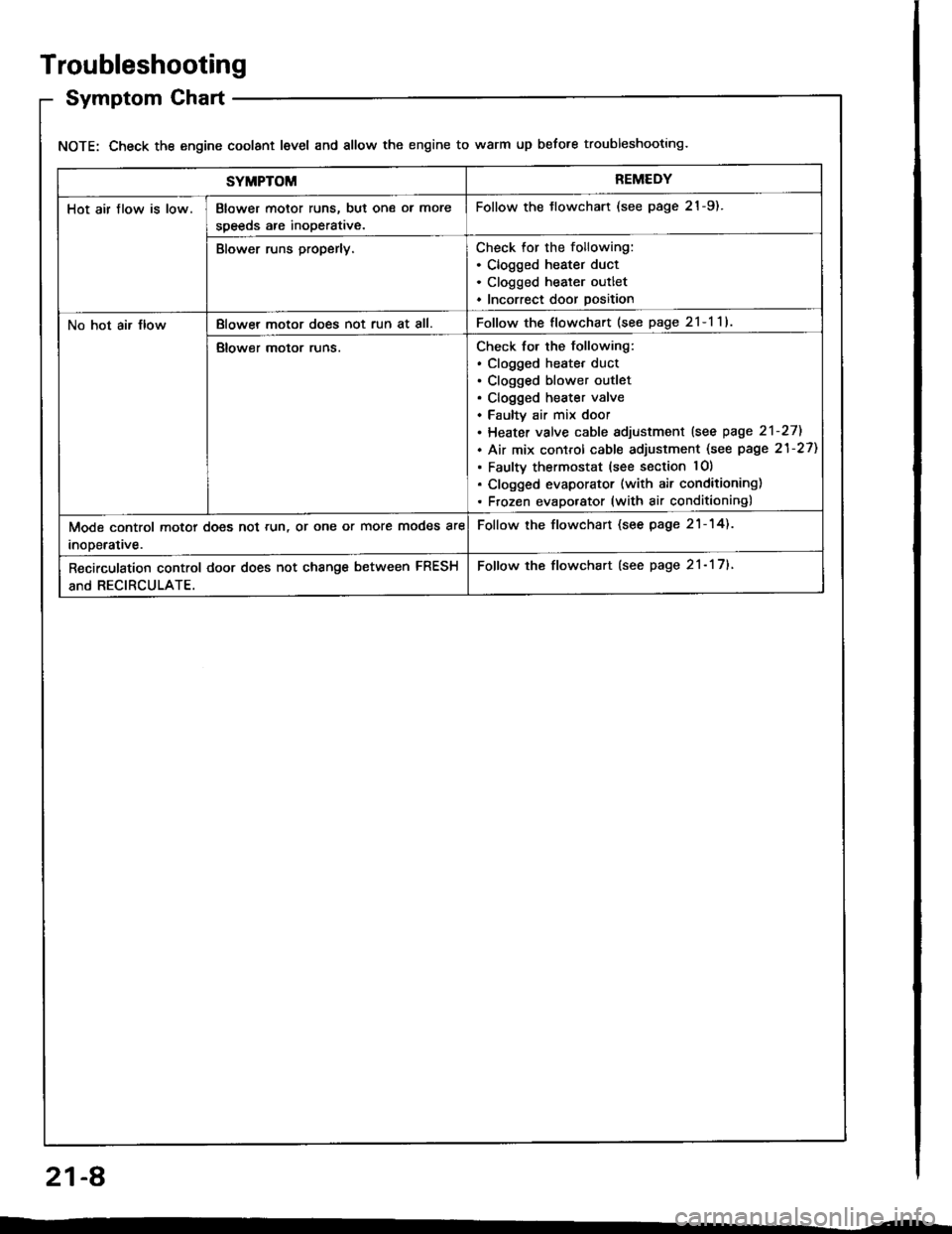
Symptom Chart
NOTE: Check the engine coolant level and allow the engine to warm up before troubleshooting.
SYMPTOMREMEDY
Hot air flow is low.Blower motor runs, but one ol more
speeds are inoperative.
Follow the tlowchart (see page 21-9).
Blower runs properly.Check for the following:. Clogged heater duct. Clogged heater outlet. Incorrect door position
No hot air JlowBlowel motor does not run at all.Follow the flowchart (see page 2l-l1l
Blower motor runs.Check for the following:. clogged heatet duct. Clogged blower outlet. Clogged heater valve. Faultv air mix door. Heater valve cable sdjustment lsee page 2'l-271
. Air mix control cable adjustment (see page 21-27)
. Faulty thermostat (see section lO)
. Clogged evaporator (with air conditioning). Frozen evaporator (with air conditioning)
Mode control motor does not run, or one or more modes are
inooerative.
Follow the flowchart (see page 21-14).
Recirculation control door does not change between FRESH
and RECIRCULATE.
Follow the flowchart (see page 21- 17).
21-A
Page 1059 of 1413
Heater Unit
Replacement
CAUTION:
a All SRS electrical witing hame$os are covoed wlth
yollow insulation.
a Before disconnecting any patt of tho SRS wito har-
neas, connect tha shott connoctol(s|.
a Roplaco th€ enlire sffacted SRS harnosr a$smbly if
it has an opon cilcult or dsmaged wiring.
NOTE: The original radio h8s a coded theft protection
circuit. Be sure to get the customer's code number betors
- disconnecting the bafterY.
- removing the No. 32 (7.5 A) fuse from th€ under-
hood tuse/relav box.- removing the radio
After service. teconnect power to the radio and turn it
on, when the word "CODE" is displayed, enter the cus-
tomer's 5-digit code to restore radio operation.
1. When the engine is cool, dtain the engine coolant
from the radiator (see section 1O).
@@ oo not lomove tho radiator cap whan
the ongine is hol; tha ongino coolant is undot
pressure and could a€voralY tcald you.
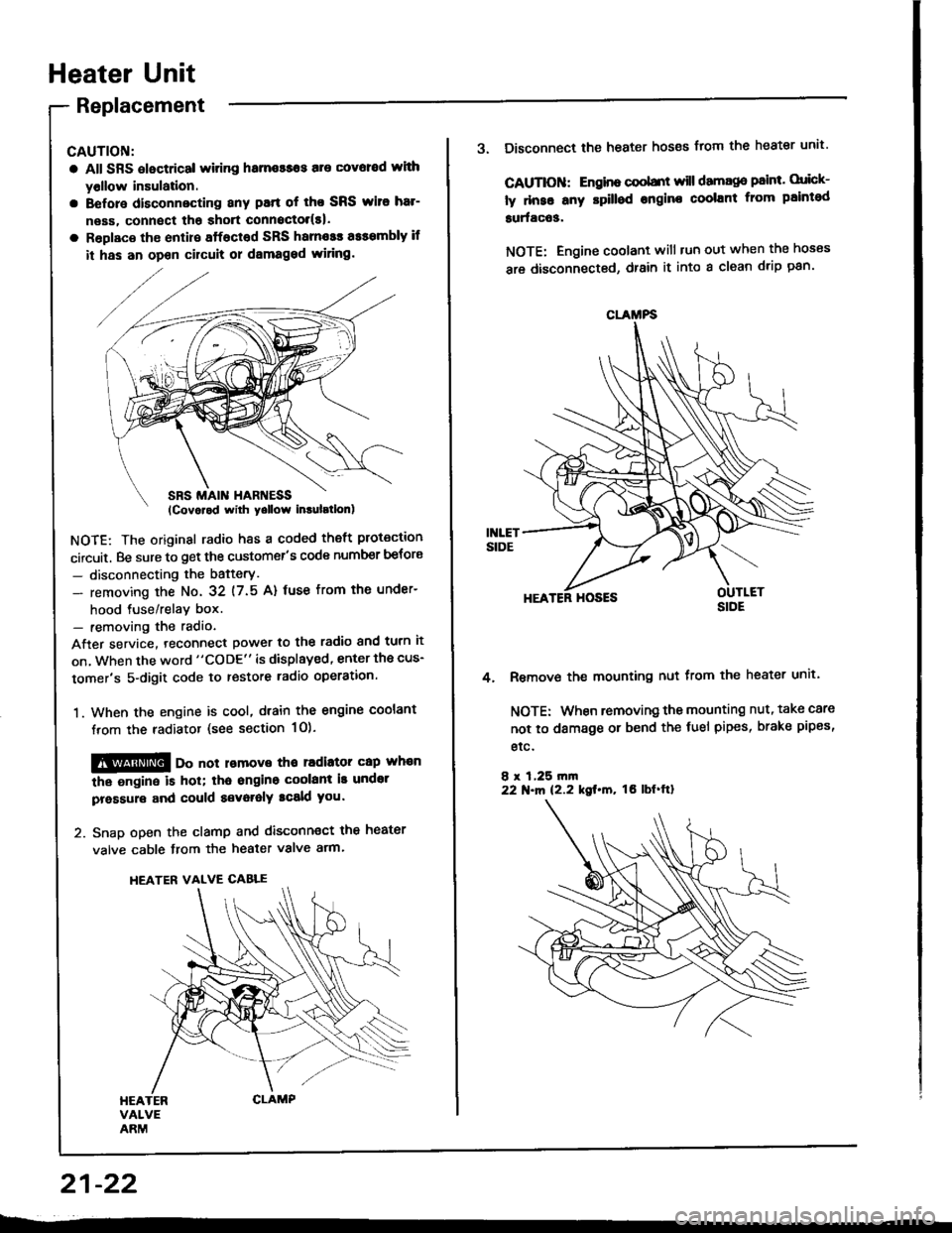
2. Snap open the clamp and disconnect the heater
valve cable from the heater valve arm.
HEATER VALVE CABLE
21-22
CLAMFS
3. Disconnect the heater hoses from the heater unit'
CAUTIOII: Engino coobnt will damago paint. orick-
ly dnse any rpilled engine coolant from paintod
surfac63.
NOTE: Engine coolant will tun out when the hoses
are disconnected, drain it into a clean drip pan'
HEATER HOSES
Remove the mounting nut from the heater unit.
NOTE: When removing the mounting nut, take care
not to damage or bend the fuel pipes, brake pipes,
etc.
8 r 1,25 rn|n22 N.m 12.2 kgt.m, tO lbf'ftl
4.