Page 1106 of 1413

A/C System Service
Leak Test
Only use service equipment that is U.L.-listed and is cer-
tified to meet the requirements of SAE J2210 to remove
HFC-134a (R-134a) from the air conditioner system.
CAUTION: Exposura to air condition ratrigerant and
lubaicant vapor or mist can irritato oyes. nose and
throat. Avoid br€athing tho sir conditionsr reftigolant
and lubricant vapor or mist.
lf accidental svstem discharge occurs, ventilate work
area before resuming service.
R-134a service equipment or vehicle air conditioner sys-
tems should not be pressure tested or leak tested with
comoressed air.
@ some mixturos ot air and R'13'la have
b.6n shown to b€ combustible at glsvated pressur€s
and can result in firo or sxplo3ion causing iniury or
proporty damage. Ngvar uso compress€d tir to pro33ure
tost R-134a $rvics oquipmont or vohicl€ air Gonditionsr
systcms.
Additional health and satetY information may be ob-
tained from the refrigerant and lubricant manufactures'
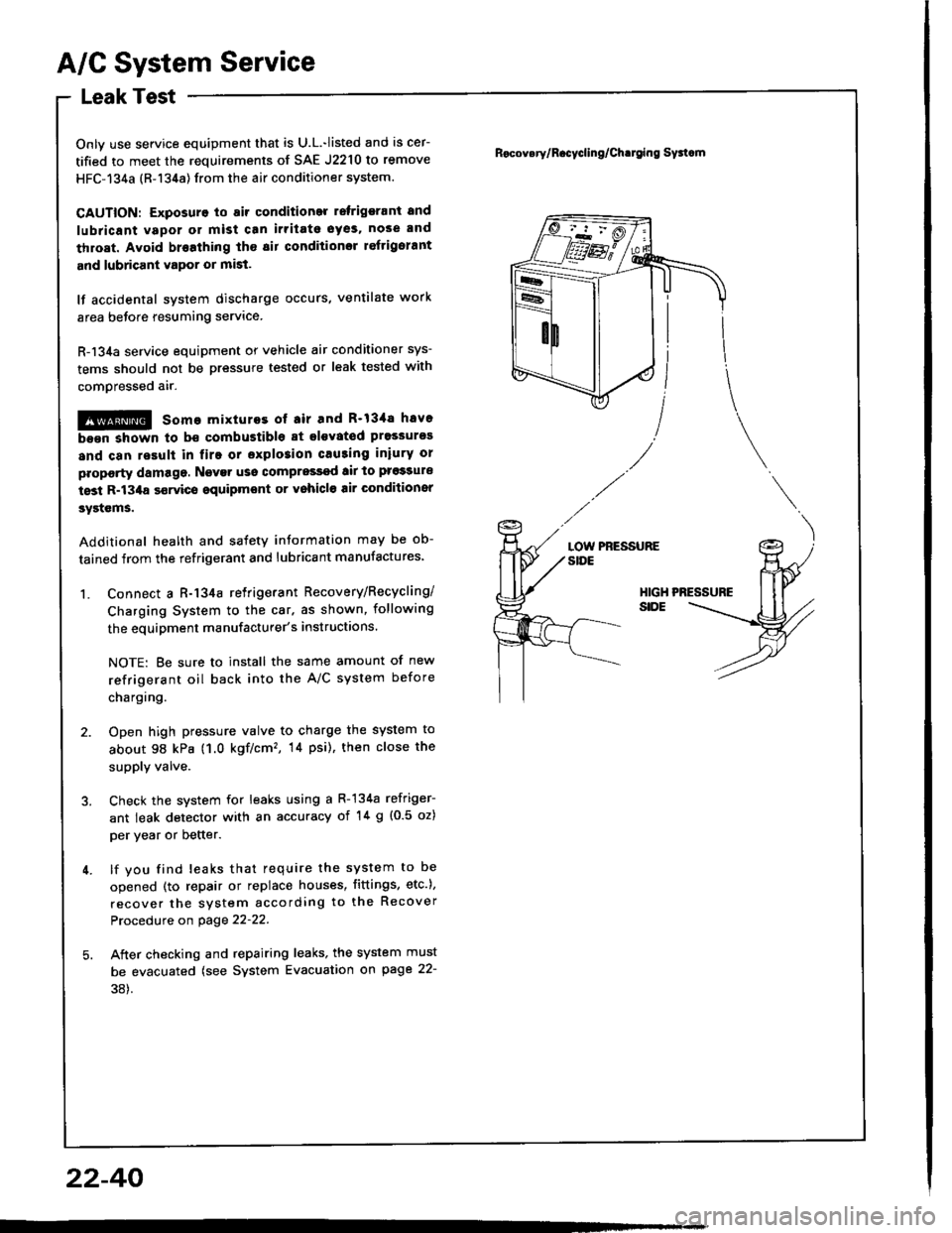
1. Connect a R-134a retrigerant Recovery/Recycling/
Charging System to the car. as shown, following
the equipment manufacturer's instructions.
NOTE: Be sure to install the same amount of new
refrigerant oil back into the A/C system before
chargtng.
2. Open high pressure valve to charge the system to
about 98 kPa (1.0 kgf/cm'�, 14 psi), then close the
supply valve.
3. Check the system for leaks using a R-134a refriger-
ant leak detector with an accuracy of '!4 g {0.5 oz)
per year or better.
4. lf you find leaks that require the system to be
opened (to repair or replace houses, fittings, etc.),
recover the system according to the Recover
Procedure on page 22-22.
5. Aiter checking and repairing leaks, the system must
be evacuated (see System Evacuation gn page 22-
38).
Rocov.ry/R.cycling/Ch.tging Sy3tcm
LOW PRESSURESIDE
HIGHSIDE
22-40
Page 1120 of 1413

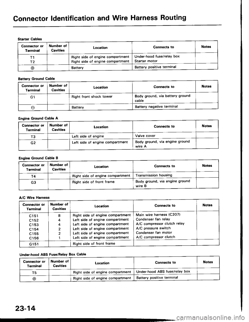
Gonnector ldentification and Wire Harness Routing
Startol cablos
Connector or
Terminal
Numbsr of
CavitiesLocationConnects toNotos
T1
r2
Right side of engine compartment
Right side of engine compartment
Under-hood fuse/relay box
Starter motor
@BatteryBattery positive terminal
B8ttory Ground Cable
Engine Ground Cable A
Engine Ground Cable B
A/C Wiro H81n6ss
Under-hood ABS Fus€/Relav Box Cablo
Conn€ctor or
T€rminal
Numbor of
CsvitiesLocationConnects toNotos
G1Right front shock towerBody ground, via battery ground
cable
\lBatteryBattery negative tetminal
Connoctor or
Tolminal
Number of
CavitiesLocationConnocta toNotes
T3Left side of engineValve cover
G2Left side of engine compartmentBody ground. via engine ground
wire A
Connoctor or
Torminal
Number ol
CavitiosLocationConnocts toNot€s
r4Right side of engine compartmentTransmission housing
G3Right side of front frameBody ground, via engine ground
wire B
Connoctor 01
Terminal
Numbor of
CavitiesLocationConnects toNotes
cl51
cl52
c153
c1 54
c155
c156
I
4
4
1
Right side ol engine comPartment
Left side of engine compartment
Left side of engine comPartment
Lett side ot engine compartment
Left side of engine comPanment
Left side of engine compartment
Main wire harness (C2O7)
Condenser fan relay
A/C compressor clutch relay
A/C pressure switch
Condenser fan motor
A/C compressor clutch
G151Right side of tront Jrame
Conngctor or
Terminal
Numbor ot
Caviti€sLocalionConnects loNotes
T5Right side of engine comPartmentUnder-hood ABS fuse/relay box
@Right side of engine compartmentBattery positive terminal
23-14
Page 1122 of 1413

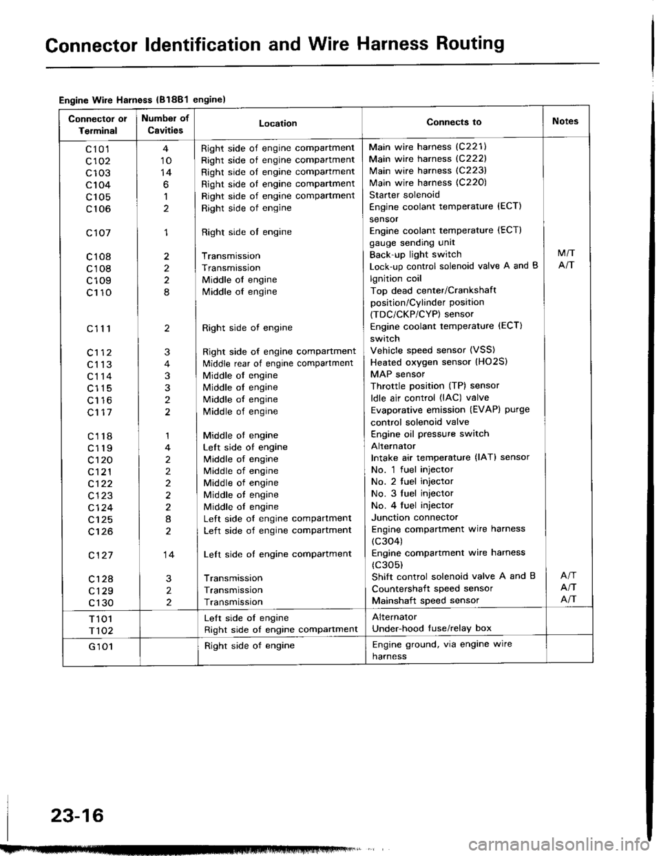
Gonnector ldentification and Wire Harness Routing
Engine Wire Harness {B1881engine)
Connector 01
Terminal
Number of
CavitiesLocationConnects ioNotes
c10'l
c102
c103
c104
c 105
c106
c107
c108
c108
c109
c110
c111
c113
c114
c115
Lt to
c117
c118
c119
c't 20
c121
c122
c123
cl24
c125
c't26
c127
c128
c129
c130
10
14
6
1
1
2
2
8
2
3
t
1
2
2)
2
8
14
2
2
Right side of engine compartment
Right side of engine compartment
Right side of engine compartment
Right side ol engine compartment
Right side of engine compartment
Right side of engine
Right side ol engine
Transmission
Transmission
Middle of engine
lvliddle of engine
Right side ot engine
Right side of engine compartment
ldiddle rear of engine compartment
Middle of engine
Middle ol engine
Middle of engine
Middle of engine
Middle ot engine
Left side of engine
lvliddle of engine
Middle of engine
Middle of engine
Middle ot engine
Middle ol engine
Left side of engine compartment
Left side of engine compartment
Left side of engine compartment
Transmission
Transmission
Transmission
Main wire harness (C221)
Main wire harness {C222}
Main wire harness (C223)
Main wire harness {C220)
Starter solenoid
Engine coolant temperature {ECT)
sensor
Engine coolant temperature (ECT)
gauge sending unit
Back'up light switch
Lock-up control solenoid valve A and B
lgnition coil
Top dead center/Crankshaft
position/Cylinder position
(TDC/CKP/CYP) sensor
Engine coolant temperature (ECT)
switch
Vehicle speed sensor (VSS)
Heated oxygen sensor (HO2S)
MAP sensor
Throttle position (TP) sensor
ldle air control (lAC) valve
Evaporative emission (EVAPI purge
control solenoid valve
Engine oil pressure switch
Alternator
Intake air temperature {lAT} sensor
No. 'l fuel injector
No. 2 tuel injector
No. 3 fuel injector
No. 4 fuel injector
Junction connector
Engine compartment wire harness
(c304)
Engine compartmenl wire harness
(c305)
Shift control solenoid valve A and B
Countershait speed sensor
Mainshaft speed sensor
M/T
NT
NT
NT
T 101
r102
Lelt side oI engine
Right side of engine compartment
Alternator
Under-hood tuse/relay box
G 101Right side of engineEngine ground, via engine wire
harness
23-16
Page 1124 of 1413

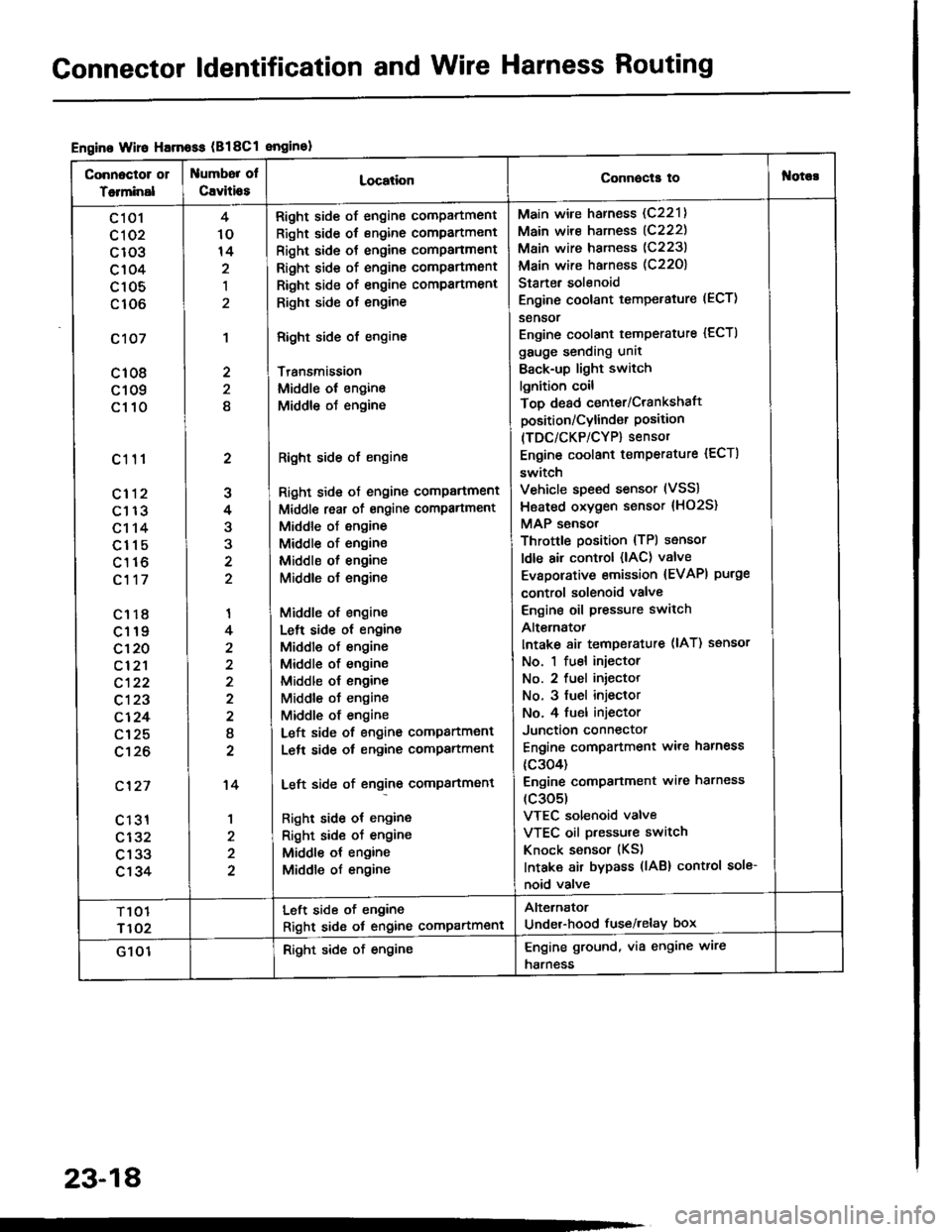
Gonnector ldentification and Wire Harness Routing
Engine Wire Harnoss (B18Cl enginol
Connoctor 01
Totminal
umbor ol
Cavitio8LocationConnecla tof{orc!
c 101
cl 02
c103
c104
c105
c106
c107
c108
c109
c110
c111
cl12
c113
c114
c115
c116
c117
c1r8
c119
c120
cl2'l
c122
c123
c124
c125
c't26
c'127
c 131
c132
c133
c134
2
J
4
3
'I
4
2
I
2
't4
1
4
10
14
,l
2
2
8
Right side of engine compartment
Right side of engine compartment
Right side ot engine comPanment
Right side of engine compartmsnt
Right side of engine compartment
Righr side ot engine
Right side of engine
Transmission
Middle ol engine
Middle oJ engine
Right side of engine
Right side ot engine comPartment
Middl€ reat of engine compartment
Middle of engine
Middle of engine
Middle ol engine
Middle o{ engine
Middle of engine
Lelt side ot engine
Middle of engine
Middle of engine
Middle ol engine
Middle ot engine
Middle of engine
Left side of engine companment
Lelt side ot engine compartment
Left side of engine compartment
Right side ot engine
Right sid€ of engine
Middle ot engine
Middle of engine
Main wire harness (C221)
Main wire harness (C222)
Main wire harness (C223)
Main wire harness (C22O)
Starter solenoid
Engine coolant temperature (ECT)
sensor
Engine coolant temperature {ECTI
gauge sending unit
Back-up light switch
lgnition coil
Top dead center/Crankshaft
position/Cylind€r Position(TDC/CKP/CYP) sensor
Engine coolant temperature {ECT)
switch
Vehicle speed sensor (VSS)
Hsated oxygen sensor {HO2S}
MAP sensor
Throttle position {TPl sensor
ldle air control (lAC) valve
Evaporative emission {EVAPI purge
control solenoid valve
Engine oil pressure switch
Alt€rnatot
Intake 8ir temperature (lAT) ssnsor
No. 1 fuel injector
No. 2 fuel iniector
No. 3 fuel injeclor
No. 4 fuel injector
Junction connector
Engine compartment ware harness
{c304)
Engine comPanment wire harness
(c305)
VTEC solenoid valve
VTEC oil pressure switch
Knock sensor (KS)
Intaka air bypass (lAB) control sole-
noid valve
T101
r102
Left side of engine
Right sid6 ot engine compartment
Alternator
Under-hood fuse/relay box
G 101Right side of engineEngine ground, via engine wire
harness
23-18