Page 653 of 1413
Steering Gearbox
Removal (cont'dl
Remove the return pipe clamp from the left side of
the rear beam. and move the return piDe above the
steering gearbox.
Remove the rear beam brace.
Remove the left tie-rod end, then slide the rack
the way to the right.
11.
12.
RETURN PIPE CLAMP
13.
I.TFT TIE-ROD END
14. Disconnect the two lines from th€ valve bodv unit
on the steering gea.box.
CAUTION: Aftor dkconnccting tho ho3o and pip.,
plug or r.d thc ho3. rnd pipc whh I pioco of tapo
or .quivll.nt to prcvont torcign m!tori!|3 f.om
ritrdng thc vdv. body unit.
NOTE:
. Place the pipe disconnected in the previous step
at the rear side of the gearbox so that they do
not hinder in the gearbox removal.
. Do not loosen the cylinder pipes A and B be-
tween the valve body unit and cylinder,
RETUR]T HOSE
15. Remove the steering gearbox mounting bolts.
GEARBOX MOU NNG BOLTS
17-46
Page 656 of 1413
Remove the cylinder pipe A and B from the gear-
box.
Drain the fluid from the cylinder fittings by moving
the steering rack back and forth,
Remove the two flange bolts, then remove the valve
body unit from the gearbox. {See page 17-51 for
valve body unit disassembly.)
FLANGE BOLT
CYLINDER PIPE B
VALVE BODY UNIT
11.Drill a 3 mm {0.12 in) diameter hole approximately
2.5 - 3.5 mm (0.10 - 0.14 in) in depth in the staked-
point on the cylinder.
NOTE: Do not allow metal shavings to enter the
cylinder housing.
STAKEO POINT
D.prh:2.5 - 3,0 mm 10.10 - 0.12 inl
CYUNDER END
12. Install a puller yoke to the stesring gearbox. Clamp
the puller yoke in a vise with soft iaws as shown,
then loosen and remove the cvlinder end.
PULLER YOKE:Commercirlly AvrilabloSn.p-Ono T/N qrie'-1
oTclo T/N 7372
(cont'd)
17-49
Page 658 of 1413
20.Apply vinyl tape to the pinion shaft.
Separate the valve housing from the pinion shafv
valve using a press.
VALVE HOUSING
Vinyl t.p.
Check the inner wall of the valve housing where the
seal ring slides with your finger. lf there is a step in
the wall, the valve housing is worn. Replace the
valve housing.
NOTE:
There may be the sliding marks from the seal
ring on the wall of the valve housing. Replace
the valve housing only the wall is stepped.
When the valve housing is replaced, install new
32 mm shim(s) on the bearing surface of the
housing to adjust the thickness.
21.
22.
23. Check fo. wear. burrs and other damage to the
edges of the grooves in the sleeve.
NOTE: The pinion shaft and sleeve are a precision
matched set. It either the pinion shaft or sleeve
must be replaced, replace the both parts as a set.
SLEEVE SEAL RINGSCh6ck for oeel off oroamag0,
24. Remove the circlip and pinion shaft sleeve from the
oinion shaft.
(cont'd)
17-51
Page 659 of 1413

Steering Gearbox
Disassembly (cont'dl
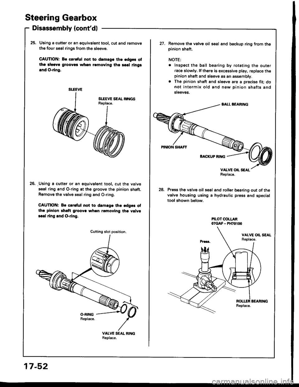
25. Using a cutter or an equivalent tool, cut and remove
the four seal rings from the sl6eve.
CAUTION: Bc clroful not to drmrg. ths .dgc. otthc alcava g1oov6 whan rcmoving the 3cd rings
lnd O.ring.
Using a cutter or an gquivalent tool, cut the valve
seal ring and O-ring Et the groove the pinion shaft.Remove the valv€ saal ring 8nd O-ring,
CAUTION: Br crrltul not to drm.gr thc cdgct ofthc plnion rhdt grooya whcn rcmoving the vllvc
!.!l ring rnd O-ring.
26.
SI-EEVE
Cutting slot position.
17.52
Remova the valve oil seal 8nd backup ring from thepinion shaft.
NOTE:
. Inspect the ball bearing by rotating the outer
race slowly. lf thsre is excessive play, replace thepinion shaft and sleeve as an assembly.. The pinion shaft and sleeve are a precise fiu donot intermix old and new pinion shafts and
steev8s,
28, Press th6 valve oil s€al and roller besring out ofthe
valve housing using a hydraulic press and specialtool shown below.
PILOT COLLARO?GAF - PHTO1OO
Page 660 of 1413
Reassembly
NOTE:
. Clean the disassembled parts with a solvent and dry them with compressed air. Do not dip the rubber parts in a sol-
vent.
. Always replace the O-rings and rubber seals with new ones before assembly.
. Apply power steering fluid or steering grease {HONDA P/N: 08733 - 8070E) to the parts indicated in the assembly pro-
cedures.
. Do not allow dust, dirt. or other foreign materials to enter the power steering system.
. Use the appropriate specialtools where necessary.
FLANGC BOLT20 N.m 12.0 kg{.m, lil lbt'ftl
CYLINDER PIPE A26 N'm (2.7 kgf.m, 20 lbf.ftl
VALVE I{OUSING
BOLI..ER BEARINGReplace.
VALVE SEAL RINGReplace.+-cncl|P
RACK GUIDE SCREW
S1IEVE SEAI RINGSReolace.
SITEVE
BACKUP RIM}
VALVE SEAL RINGRaplacs.
O.RINGReplac€.LOCKNUT
CYLINDER HOUSING
O-RINGBACKUP RING Replace.
\
PINION SHAFT
SHIMS
O-RINGReplace.
CYUNDER END SEALReolace.GEAR HOUSING
CYLINDER END SEALReplaco.O.RINGReplace.
I
x nd#$Y
IPISTON SEAL RINGReplace.
STEERING RACK
(cont'd)
17-53
Page 661 of 1413

Steering Gearbox
Reassembly lcont'd)
Vllvc Body Rea3sombly
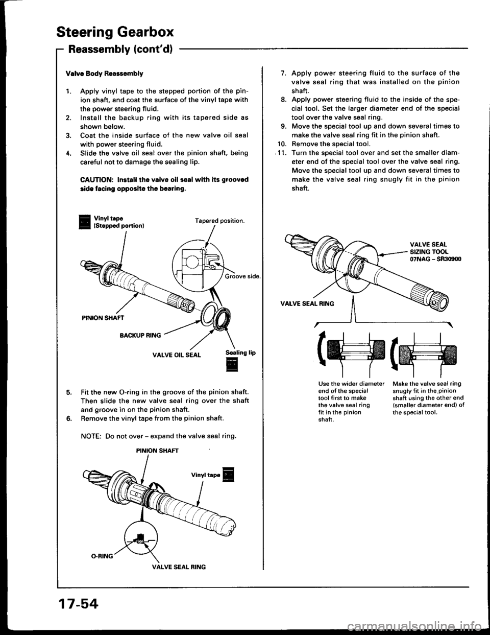
1. Apply vinyl tape to the stepped portion of the pin-
ion shaft, and coat the surface of the vinyl tape with
the power steering tluid,
2. Install the backup ring with its tapered side as
shown below.
3. Coat the inside surface of the new valve oil seal
with power steering fluid.
4. Slide the valve oil seal over the pinion shaft. being
careful not to damage the sealing lip.
CAUTION: ln3tall the valve oil ssal with hs groovad
3ide tacing opposits the besring.
Vinyl trpolst.ppcd ponion,Tapered position.
Groove side.
VALVE OIL SEAL
Fit the new O-ring in the groove of the pinion shaft.
Then slide the new valve seal ring over the shaft
and groove in on the pinion shaft.
Remove the vinyl tape from the pinion shaft.
NOTE: Do not over - expand the valve saal ring.
S€aling
E
lip
PINION SHAFT
VALVE SEAL RING
17-54
7. Apply power steering fluid to the surface of the
valve seal ring that was installed on the pinion
shaft.
8. Apply power steering fluid to the inside of the spe-
cial tool. Set the larger diameter end of the special
tool over the valve seal ring.
9. Move the special tool up and down several times to
make the valve seal ring Jit in the pinion shaft.
10. Remove the special tool.
.11. Turn the special tool over and setthe smallerdiam-
eter end of the special tool over the valve seal ring.
Move the sDecial tool uD and down severai times to
make the valve seal ring snugly fit in the pinion
shaft.
VALVE SEAL RING
(H(ffi
Use the wider diameterend ot the specialtool first to makethe valve seal ringfit in the pinionshaft.
Make the valve seal ringsnugly fit in the.pinionshaft using the other end(smaller diameter end) ofthe specialtool.
Page 662 of 1413

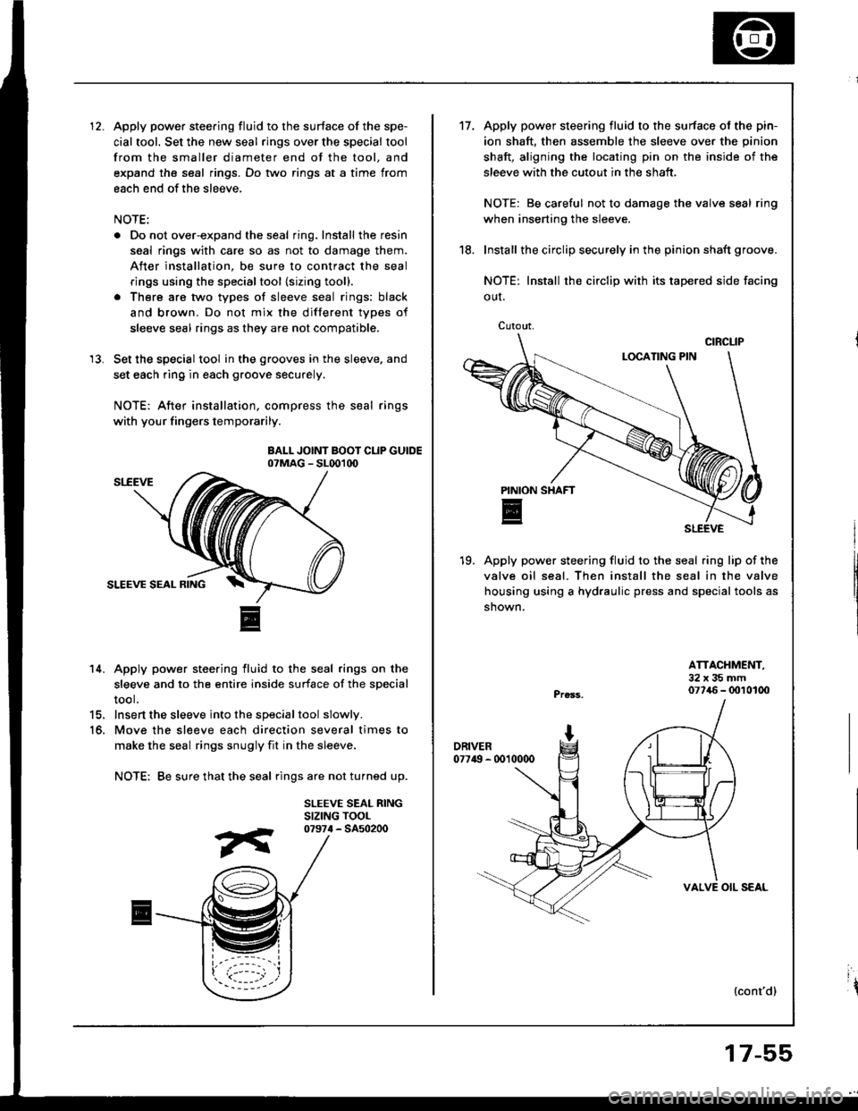
Apply power steering fluid to the surface of the spe-
cial tool. Set the new seal rings over the special tool
from the smaller diameter end of the tool, and
expand the seal rings. Do two rings at a time from
each end of the sleeve,
NOTE:
. Do not over-expand the seal ring. Install the resin
seal rings with care so as not to damage them.
After installation, be sure to contract the seal
rings using the specialtool {sizing tool}.
. There are two types of sleeve seal rings: black
and brown. Do not mix the different types of
sleeve seal rings as they are not compatible.
Set the special tool in the grooves in the sleeve. and
set each ring in each groove securely.
NOTE: After installation, compress the seal rings
with your fingers temporarily.
BALL JOINT BOOT CLIP GUIDEo?MAG - SL001d)
14. Apply power steering fluid to the seal rings on the
sleeve and to the entire inside surface of the special
tool.
15. Insert the sleeve into the specialtool slowly.
16. Move the sl€eve each direction several times to
make the seal rings snugly fit in the sleeve.
NOTE: Be sure that the seal rings are not turned up.
SLEEVE SEAL RINGSIZING TOOL
13.
07974 - 5450200
Cutout,
't7.Apply power steering fluid to the surface ol the pin-
ion shaft, then assemble the sleeve over the pinion
shaft, aligning the locating pin on the inside of the
sleeve with the cutout in the shaft,
NOTE: Be careful not to damage the valve seal ring
when inserting the sleeve.
Install the circlip securely in the pinion shaft groove.
NOTE: Install rh€ circlip with its tapered side facing
OUI.
19. Apply power steering fluid to the seal ring lip of the
valve oil seal. Then install the seal in the valve
housing using a hydraulic press and special tools as
shown.
18.
ATTACHMENT,32x35mm077{6 - 0010100
{cont'd)
VALVE OIL SEAL
17-55
ir
Page 663 of 1413
Steering Gearbox
Reassembly (cont'd)
SI,-EEVE SEAL RINGSBe sure that thesear ings are notturned up, theninstall.
Press the new roller bearing into the valve housing
using a hydraulic press and special tool as shown.
NOTE: Place ths roller bearing on the valve hous-
ing with its letter stamped facing up towards the
valve side.
Pr.33,
I
PINION
E
20.
ATTACHMENT,32x35mm077/aO - (x)1010O
ROLLER BEARINGLetter stamped face
21.Apply vinyl tape to the pinion shaft, then coat thevinyl tape with power steering fluid.
Insert the pinion shaft into the valve housing.
CAUTION: Be carotul not to damage tho valvs soalrings.
23. Remove the vinyltape from the pinion shaft.
Soaling lip frc..
VALVE OIL SEAL
VALVC HOUSING
17-56
24. Press the pinion shaft/sleeve using a hydraulic
Dress as shown.
CAUTION: Before irserting the pinion 3haft, bosuro that the backup ring is csntored with the pin.
ion shaft bearing,
BACKUP BING