Page 612 of 1413
Construetion
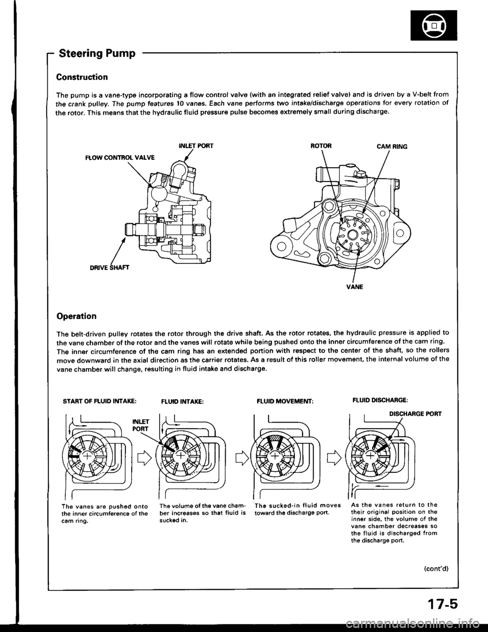
The pump is a vane-type incorporating a flow control valve (with an integrated relief valve) and is driven by a V-belt from
the crank pulley. The pump features 10 vanes, Each vane performs two intake/dischsrge operations for every rotation of
the rotor. This means that the hydraulic fluid pressure pulse becomes extremely small during discharge.
CAM RING
FLOW CONTBOL VALVE
DRIVE
Operation
The belt-driven pulley rotates the rotor through the drive shaft, As the rotor rotates, the hydraulic pressure is applied to
the vane chamber of the rotor and the vanes witl rotate while being pushed onto the inner circumference of the cam .ing.
The inner circumference of the cam ring has an extonded portion with respect to the center of the shaft. so the rollers
move downward in the axial direction as the carrier rotates. As a result of this roller movemsnt, the internal volume of the
vane chamber will change, resulting in fluid intake and discharge.
START OF FLUID INTAKE:FLUID INTAKE:FLUID MOVEMENT:FLUID DISCHABGE:
DISCHARGE P('BT
I
SHAF'
The vanes are pushed ontothe inner circumference of th6cam ring.
Th6 volums otth€ van€ cham-ber increasos so that lluid issuckod in.
Th6 sucked-in fluid moves
towsrd the discha196 pon.As the vanes return to th€their original position on theinner side, the volume of thevane chamber decreases sothe fiuid is discharg6d fromthe discharge port.
(cont'd)
INLET PORT
VANE
Page 613 of 1413
System Description
Steering Pump (cont'dl
Flow Control
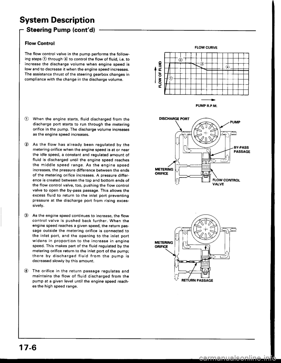
The flow control valve in the pump performs the follow-
ing steps @ through O to control the flow of fluid, i.e. to
increase the discharge volum€ wh6n engine speed is
low and to decrease it when the engine speed increases.
The assistance thrust of the steering gearbox changes in
compliance with the change in the discharge volume.
When the engine starts, fluid discharged from the
discharge port starts to run through the metering
orifice in the pump. The discharge volume increas€s
as the engine speed increases,
As the flow has already been regulated by the
metering orifice when the engine speed is at or near
the idle speed, a constant and regulated amount ot
fluid is discharged until the engine speed reaches
the middle speed range. As the engine speed
increases, the pressure difference between the ends
of the metering orifice increases. A pressure differ-
ence is created between the top and bottom ends ofthe flow control valve, too, pushing the flow control
valve to open the by-pass passage. This allows the
excess fluid to return to the inlet pon preventing
pressure at the discharge port trom rising exces-
sively.
As the engine speed continues to increase, the tlow
control valve is pushed back further. When the
engine speed reaches a given speed. the return pas-
sage outside the metering orifice is connected to
the inlet port, and the opening to the inlet port
widens in proportion to the increase in engine
speed. This makes pan of the fluid regulated by the
metering orifice return to the inlet pon of the pump;
there by discharged fluid from the pump is
decreased slowly by this amount.
The orifice in the return passage regulates and
maintains the flow of fluid discharged from thepump at a given level until the engine speed reach-
es the high speed range.
.5IJ
lot=ro
FLOW CURVE
PUMP R.P,M.
o
@
VALVE
@
@
17-6
Page 614 of 1413
Pressure Relief
Pressu.6 outside of the metering orifice is directed to
the bonom ot the flow control valve. When the pressure
builds up, the reliet valve in the flow control valve opens
to relieve the pressure. As the flow control valve is
pushed back by the pressure difference this time, the
flow of fluid in the bypass passsge increases, convolling
the pressure outside the metering orifice. The above
operations are repeated to provide constant discharge
prsssure lrom the pump,
VALVE
{Dacrarlai cxco33ivaYibration in iha valva.l
(cont'dl
17-7
Page 615 of 1413
System Description
Steering Gearbox
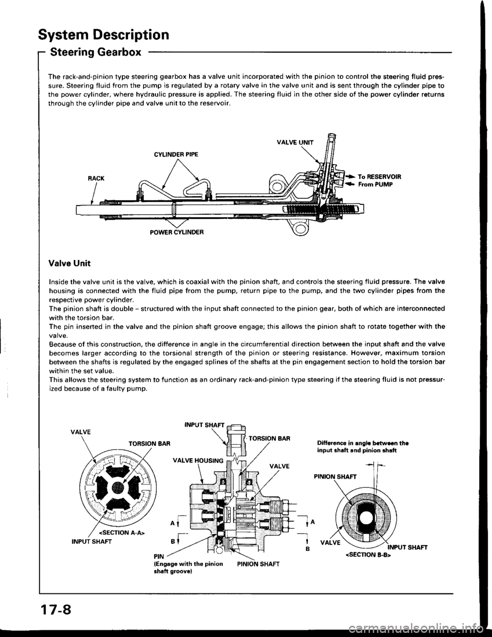
The rack-and-pinion type steering gearbox has a valve unit incorporated with the pinion to control the steering fluid pres-
sure. Steering fluid from the pump is regulated by a rotary valve in the valve unit and is sent through the cylinder pipe to
the power cylinder, where hydraulic pressure is applied. The steering fluid in the other side of the power cylinder returns
through the cylinder pipe and valve unit to the reservoir.
VALVE UNIT
CYLINDER PIPE
POWEB CYLINDER
Valve Unit
Inside the valve unit is the valve, which is coaxial with the pinion shaft, and controls the steering fluid pressure. The valve
housing is connected with the fluid pipe from the pump, return pipe to the pump, and the two cylinder pipes from the
respective power cylinder.
The pinion shaft is double - structured with the input shaft connected to the pinion gear, both of which are interconnected
with the torsion bar.
The pin insened in the valve and the pinion shaft groove engage; this allows the pinion shaft to rotate together with the
Because of this construction, the difference in angle in the circumferential direction between the input shaft and the valve
becomes larger according to the torsional strength of the pinion or steering resistance. However, maximum torsion
between the shafts is regulated by the engaged splines of the shafts at the pin engagement section to hold the torsion bar
within the set value.
This allows the steering system to lunction as an ordinary rack-and-pinion type steering if the steering fluid is not pressur-
ized because of a faulty pump.
VALVE
Difforcnco in .ngl. bo{w€cn thainput shalt rnd pinion !h.tt
ln-1
B
lEngag€ with the pinionshaft groove)
17-8
INPUT SHAFT
Page 616 of 1413
Pressure Control
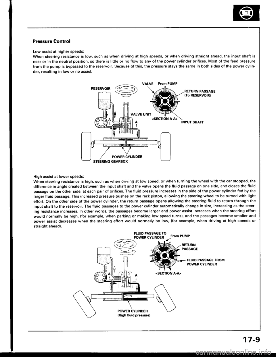
Low assist at higher speeds:
When steering resistance is low. such as when driving at high speeds. or when driving straight ahead, the input shaft is
near or in the neutral position, so there is little or no flow to any of the power cylinder orifices, Most of the feed pressure
trom the pump is bypassed to the reservoir. Because of this, the pressure stays the same in both sides of the power cylin-
der, resulting in low or no assist.
vaz =- S\->/-\7/RETURN PASSAGE(To RESERVOIRI
VALVE UNITINPUT SHAFT
High assist at lower speeds:
When steering resistance is high, such as when driving at low speed, or when turning the wheel with the car stopped, the
difference in angle created between the input shaft and the valve opens the fluid passage on one side, and closes the fluid
passage on the other side, at each pair of orifices. The fluid pressure increases in the side of the power cylinder fed by the
larger fluid passage. This increased pressure pushes on the rack piston, allowing the steering wheel to be turned with light
effon. On the other side of the power cylinder, the return passage opens allowing the steering fluid to return through the
input shaft to the reservoir. The fluid passages to the power cylinder automatically change in size, increasing as the steer-
ing resistance increases. In other words, the passages become larger and power assist increases when the steering effort
would normally be high, (for example. when parking or making low speed turns). and the passages become smaller and
power assist decreases when the steering effort would normally be low, (for example, when driving at high speeds or
straight ah€ad).
FLUIO PASSAGE TOPOWER CYLINDERFrom PUMP
A
/t-:\
v"
=iJ
RETURNPASSAGE
FLUID PASSAGE FROMPOWER CYLINDER
ALVE F.om PUMP
RESERVOIR
Page 617 of 1413

Troubleshooting
General Troubleshooting
Check the following betore you begin:
. Has the susp€nsion been modified in a way that would affect steering?. Are tire sizes and air pressure correct?
. ls the steering whe€l original squipment or equivalent?
. ls the power steering pump belt properly adiusted?
o ls steering fluid reservoir filled to proper level?
o ls the engine idle speed correct and steady?
Normal reliel pressure
I
I
Go to pate tu.l t
r Fluid pro$ure is too low:Chock th€ rgturn circuit pipe and hose between thogearbox and pump tor clogging and dotormation.* Fluid pressure is too hioh:Check the pipe and hosg connected from th6 pumpto tho georbox tor clogging and delormation.
Check pump fluid pressurg (soepage 17-221,Measure steady-state fluid pres-sure while idling with the shut-offvalve fully open.Ir shoutd be 1,500 kPa (15 kgtcm'�, 213 psi) or bolow.
Normal
Check pump fluid pr€ssur€ {se€page 17-221.Measure pump relief pressurewhile idling with the shut-offvalve fully closod.h should be 6,400 - 7,400 kPa {65- 75 kgtcm,, 924 - 1,067 psi)
Check the flow control valve.* Check lhe valve for smooth movement in thg hou6-Ing.* Chock thg reli€f valve for leaks.
Abnormal
I
I
Faulty flowtontroi valve
17-10
Page 620 of 1413
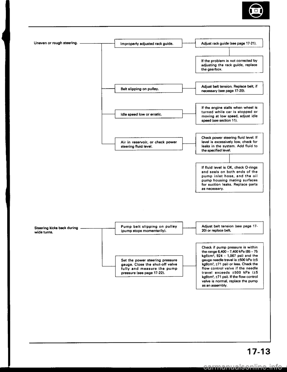
Unovon or rcugh 8te6ring.
3
Adjust rack guide (se€ poge 17-21).
ll the probl6m is not corrected bYadjusting lhe rack guide. replacothe gearbox.
Adiud bolt t€nsion. Roplace b€lt, ifn€c€ssary {s€e page 17-20).
lf the ongin€ stalls when wheel isturned whil€ car is stoDPed ormoving at low spoed, adjust idlesp€€d (soe section 1 1 ).
ldl6 soosd low or orrrtic.
Chock power sieering Iluid levol. Itlgv6l ie excessivoly low, ch€ck forleaks in the system. Add fluid totho spocifiod level.
Air in rssorvoir. or ch€ck pow6a
steoring fluid l6v6l.
lf fluid lev6l is OK, check o-ringsand seals on both €nds of ihopump inlet hose, and th€ oilpump housing mating surfacosfor suction leaks. Reolace oarts65 n€CeSSAry.
Adjust belt tonsion (see page 17-m) or r€Dlaco beh.Pump b6lt slipping on pull6y(pump stops momontarily).
Check if pump prossure is withinthe ranoe 6.400 - 7,100 kPa (65 - 75kgr/cm,, 924 - 1,067 psil and th6gsuge needls travol is 1500 kPa {15kgflctn2, t71 p6i) or less. Check theflow control valve if the needletr.vel €xcoods 1500 kPa {15kg?cm,, i71 psi). lf rhe flow controlvalvo is normal, replace th€ pump
as an assomblv.
Sel the power itooring p.oasuregaug6. Cl066 th€ shut-off v6lv6fully and m€a5uro tho pumppr6ssur6 (6s€ pagg 17-221,
7-1
Page 621 of 1413

Troubleshooting
Noise and Vibration
NOTE: Pump noise in first 2 - 3 minutes after starting in cold weather (-20.C, -4"F or colder) is normal.
Humming
Rattle or chattering
Right cylinder end soal squeak
Pump noise. though not loud,lrom the vslvo bodv unit can be heard when turn-ing the steering wheel right or left. This is normsl.
Humming due to pulsation ol fluid is no.mal, paniculady when wheel is turnedwith ca. stopped.
lf equipped with automatic trans-mission, the hum could b€ tor-que convener or pump notse.
Confirm by temporarily removingpump b€lt.
High pressure line touching theframe,Reposhion tho line.
Loose steering shaft connector.tie-rod, or balljoint.Check and tighten, or replacepa s as necessary.
Column shaft wobbling.Replace column assembly.
Check the rack guide for properadjustment (16o page 17-21).Adjust, if n€ca€ssry.
Rattling sound and feeling when turning the steoring wheel right and lett with thoengine OFF is a sound when th6 valve unit contacts tho stopper. This is normal.
Striking sound wh6n turning the ste€ring whoglfully right o. left is a sound whenthe r6ck end contacts th6 stopper. This is normal.
17-14