Page 484 of 1413

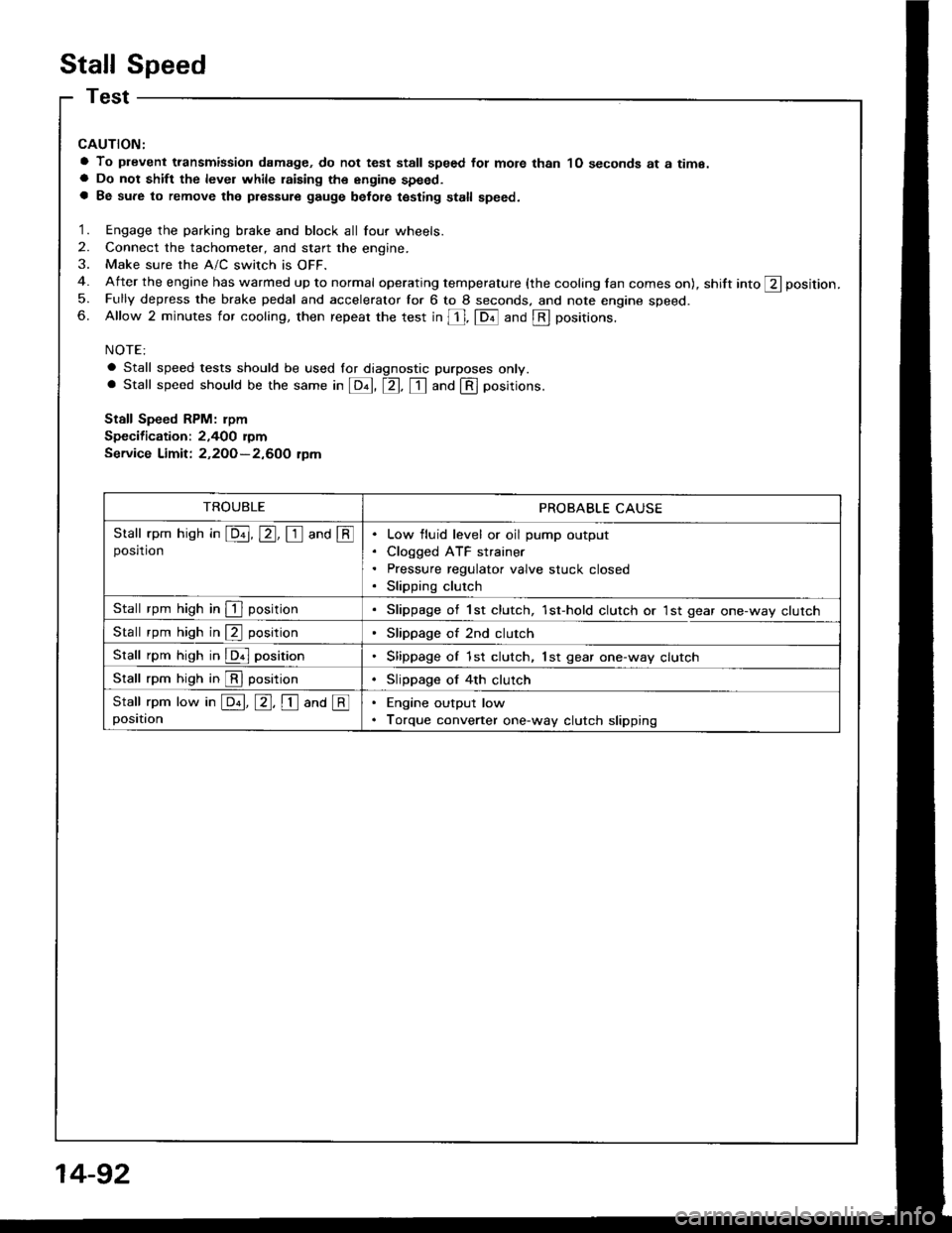
Stall Speed
CAUTION:
a To plevent transmission damage, do not test stall speed fot mote than 1O seconds at a time.a Do not shift the level while raising th€ engine speed.a Be sure to remove the pressure gauge belot€ testing stall speed.
1. Engage the parking brake and block all four wheels.
2. Connect the tachometer, and start the engine.
3. Make sure the A/C switch is OFF.
4. After the engine has warmed up to normal operating temperature (the cooling lan comes on), shift into ft position.
5. Fully depress the brake pedal and accelerator for 6 to 8 seconds. and note engine speed.6. Allow 2 minutes for cooling, then repeat the test in [, fDil and @ positions.
NOTE:
a Stall speed tests should be used lor diagnostic purposes only.. Stall speed should be the same in E, tr. tr and @ positions.
Stall Speed RPM: rpm
Specification: 2,400 rymService Limit: 2,2OO-2,600 tpm
TROUBLEPROBABLE CAUSE
Stall rpm hish in E, E, I and @posrtronLow fluid level or oil pump output
Cloqged ATF strainer
Pressure regulator valve stuck closed
Slipping clutch
Stall rpm high in I positionSlippage of 1st clutch, 1st-hold clutch or 1st gear one-way clutch
Stall rpm high in @ positionSlippage of 2nd clutch
Stall rpm high in @ positionSlippage of 1st clutch, lst gear one-way clutch
Stall rpm high in @ positionSlippage of 4th clutch
Stall rpm low in E, E, I ana @positionEngine output low
Torque converter one-way clutch slipping
14-92
Page 486 of 1413

Pressure Testing
a While testing, be caretul of the rotating flont wheels.a Make aura litts, jacks, and sat€ty stands alo placedplop6rly {see section 1}.
CAUTION: Betore t€sting, be sure the transmission fluidis tilled to rh6 ploper l€vet.
1. Raise the car (see section i),
2. Warm up the engine {the cooling fan comes onl, thenstop the engine and connect a tachometer.
3. Connect the oil pressure gauge to each inspectionholels).
TOROUE: 18 N.m (1.8 kgf.m, 13 tbf.fr)
CAUTION: Connect ths oil prsssure gauge s€cur€_ly; be sule not to allow dust and other foleign pani_cl6s to 6nt€1 th€ inspection holo.
A/T OIL PRESSURE GAUGESET WPANEL07406-002oi+oo
A/T LOW PRESSUREGAUGE W/PANEL07/rO6-0O70300
A/T OIL PRESSURE HOSE,22'10 mmOTMAJ_PY4OI TA{4 Roquirod)
A/T OIL PRESSUBE HOSEADAPTEROTMAJ - PY/+O12014 Roqui.odl
NOTE: Use the A/T Oil Pressure Gauge Set (07406_O02OOO3) or A/T Low Pressure Gauge (07406-OOTO0OO). and the oil pressure gauge hoses and adap_ters shown above.
14-94
4. Start the engine, and measure the respective pres-
sure as follows.
a Line Pressure
a Clutch Pfessure
a Clutch Low/High Pressure
a Throttle B Pressure
5. Install a new washer and the sealing bolt in the in-spection hole and tighten to the specified torque.
TOROUE: 18 N'm {1.8 kgf.m, 13 tbf.ft)
NOTE: Do not reuse old aluminum washers.
a Line Pressure M€asurement
- 1 . Set the parking brake and block both rear wheelssecurely.
-2. Run the engine at 2,OOO rpm
-3. Shift the selecr lever to S or @ position.
-4. Measure line pressure.
LINE PRESSUREINSPECTION HOLE
NoTE: Higher pressures may be indicated it measurements are made in selector positions other than @ or @ position.
PRESSURESELECTOR
POStTTONSYMPTOMPROBABLE CAUSEFLUID PRESSURE
StandardService Limit
LineNo'ENo (or low)
lrne pressureTorque converter,
orl pump, pressure
regulator, to.que
convener check
valve
83O-88O kPa(8.5-9.O kgf/cm,,
120- I 30 psi)
78O kPa
{8.0 kgl/cm,, 1lO psi}
Page 487 of 1413

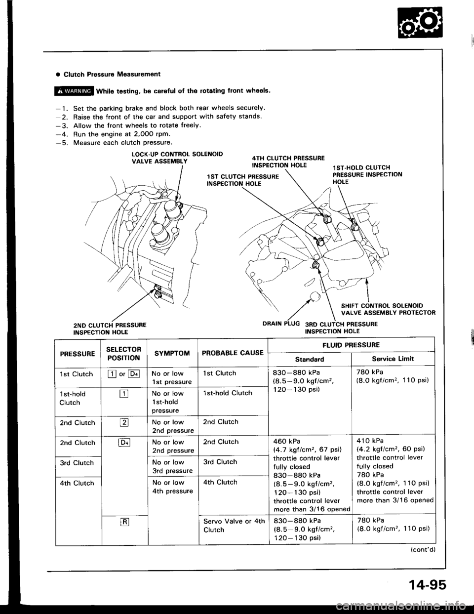
a Clutch Pressuro M€asur€ment
@ wtit" testing, be careful ot the rotating front wheols.
1. Set the parking brake and block both rear wheels securely.
2. Raise the front of the car and support with safety stands.
-3. Allow the front wheels to rotate freely,
-4. Run the engine at 2,OOO rpm.-5. Measure each clutch Pressure.
LOCK.UP CONTNOL SOLENOIDVALVE ASSEMBLY
INSPECTION HOLE
SELECTOB
POST ONSYMPTOMPROBABLE CAUSE
FLUID PRESSURE
rl|E!!UltEStandardService Limit
1st ClutchEo'ENo or low
lst Pressure
1st Clutch83O-880 kPa
(8.5-9.O kgf/cm',
120- 130 psi)
78O kPa
{8.O kgf/cm'�, 11O psi)
l st-hold
ClutchtrNo or low
1st-hold
pressure
1st-hold CIutch
2nd ClutchaNo or low
2nd pressure
2nd Clutch
2nd ClutchENo or low
2nd pressure
2nd Clutch460 kPa
|'4.7 kgt lcm2, 67 psil
throttle control lever
fully closed
830-880 kPa
(8.5 - 9.0 kgt/cm'�,
120- l30 psi)
throttle control lever
more than 3/16 opened
4'l o kPa
(4.2 kgt/cm'�, 60 psi)
throttle control lever
fully closed
78O kPa(8.O kgf/cm'�, 1 1O psi)
throttle control lever
more than 3/16 opened
3rd ClutchNo or low
3rd pressure
3rd Clutch
4th ClutchNo or low
4th pressure
4th clutch
EServo Valve or 4th
Clutch
830-880 kPa
(8.5 9.0 kqf/cm'�,
120- 130 psi)
780 kPa
(8.0 kgf/cm'�, 1 1O psi)
(cont'd)
14-95
Page 489 of 1413
LOCK.UP CONTROLSOLENOID VALVE4TI{ CLUTCH PRESSUREINSPECTION HOLE
SHIFT CONTROLSOLENOID VALVEASSEMBLY PROTECTOR
3RD CLUTCH PRESSUREINSPECTION HOLEINSPECTION HOLE
PRESSUNESELECTOR
POStTtONSYMPTOMPROBABLE CAUSEFLUID PRESSURE
StandardService Limit
2nd ClutchENo or low
2nd pressure
2nd Clutch460-88O kPa(4.7 -9.O kgtlcmt,
67- 130 psil
varies with throttle
openrn9
41O kPa
{4.2 kgf/cm,, 60 psi}
with throttle control
lever released
78O kPa
l8.O kgtlcm,, 1'lO psil
with throttle control
lever more than 3/1 6
opened
3rd ClutchNo or low
3rd pressure
3rd Clutch
4th ClutchNo or low
4th pressure
4th Clutch
(cont'd)
14-97
Page 490 of 1413
Pressure Testing
(cont'dl
a Throttle B Ptsssure Measuremcnt
@@ wrril" resring, be caretut ot rhe rotaringfront wheels.
1. Allow the front wheels to rotate treelv.-2. Remove the cable end of the throttle controlcablefrom the throttle control lever.
NOTE: Do not loosen the locknuts, simply unhookthe cable end.
3. Shift the selector lever to @ or @ position.-4. Run the engine at 1,OOO rpm-5. Measure full-closed throttle B pressure.-6. Move the throttle control lever to full-opened throt-tle position.-7. Measure full-opened throttle B pressure.
PRESSURESELECTOR
POSTTTONSYMPTOMPROBABLE CAUSEFLUID PRESSURE
StandardS€rvica Limit
Throttle Bloil or lDllPressure too
high
Thfottle Valve BO-15 kPa
{O-O.1 5 kgf/cm,,
0-2.1 psi)
throttle control lever
fully closed
No or low
Throttle B
pressure
83o 88O kPa(8.5-9.O kgf/cmz,
120 130 psi)
thfottle control levet
fully closed
78O kPa(8.O kgl/cm,, l lO psi)
throttle control lever
tully closed
14-98
Page 491 of 1413

Transmission
Removal
4.Bemove the t.ansmission ground cable from the
transmission hanger.
Disconnect the lock-uD control solenoid valve con-
nector and the shitt control solenoid valve connec-
tor, then remove the harness clamp on the lock-up
control solenoid harness from the harness stav.
a Make sur€ lifts. iacks and safety stands are placad
properly, and hoist brackots are attachod to tho cor-
rect position on ths sngine {seo sectionl }.o Apply parking brake and block rear wheels, so car will
not roll off stands and fall on you whil6 working un-
del it
CAUTION: Use tender covers to avoid damsging paint-
ed surlaces,
1 . Disconnect the battery negative { - } and positive ( + )
cables from the battery.
2. Remove the intake air duct and air cleaner housino
assembly.
HARNESS CLAMP
LOCK-UP CONTROLSOLENOID VALVECONNECTOR
AIR CLEAI{ERHOUSING ASSEMBLY
SHIFT CONTROLSOLENOID VALVECONNECTORTRANSMISSIONGROUND CABI-E
Disconnect the vehicle speed sensor (VSS), main-
shaft sDeed sensor and countershaft speed sensor
connectors.
3.Remove the starter motor cables and cable holder
from the starter motor.VEHICLE SPEEDSENSOR CONNECTOR
STARTER MOTOR CABLECABLE HOLDER
VEHICLE SPEEDSENSOR
COUNTERSHAFTSPEED SENSORCONNECTOR
MAINSHAFT SPEEDSENSORCONNECTOR (cont,d)
STARTER MOTOR?/\
STARTER MOTOR CABLE
4-99
Page 498 of 1413

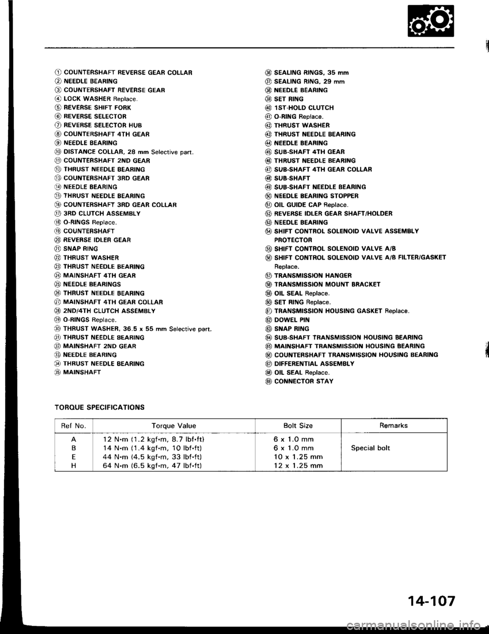
O) COUNTERSHAFT REVERSE GEAR COLLAR
@ NEEDLE BEARING
G) COUNTERSHAFT REVERSE GEAR
@ LOcK WASHER Reptace.
@ REVERSE sHIFT FoRK
@ BEVERSE SELECToR
O REVERSE SELECToR HUB
@ couNTERSHAFT 4TH GEAR
@ NEEDLE BEARING
@ DTSTANCE COLLAR, 29 mm Setecrive part.
@ coUNTERSHAFT 2ND GEAR
@ THRUST NEEDLE BEARING
@ GoUNTERSHAFT 3RD GEAR
@ NEEDLE BEARING
@ THRUST NEEDLE EEARING
G) COUNTERSHAFT 3RD GEAR COLI-AR
O 3RD cLuTcH ASSEMBLY
(!) O-RINGS Replace.
@ coUNTERSHAFT
@ REVERSE IDLER GEAR
@ SNAP RING
@ THRUST WASHER
@ THRUST NEEDLE BEARING
@ MAINSHAFT 4TH GEAR
@) NEEDLE BEARINGS
@ THRUST NEEDLE BEARING
@ MAINSHAFT 4TH GEAR coLLAR
@ 2ND/4TH cLUTcH ASSEMBLY
et O-RINGS Replace.
@ THRUST waSHER, 36.5 x 55 mm Setective pan.
@ THRUST NEEDLE EEARING
@ MA|NSHAFT 2ND GEAR
€, NEEDI.E BEARING
@ THRUST NEEDLE EEARING
.O MAINSHAFT
@ SEAL|NG RtNGs, 3s mm
@ SEAL|NG R|NG, 29 mm
@ NEEDLE BEARING
@ sET RING
@ 1ST-HOLD CLUTCH
@ O-RING Replace.
@ THRUST WASHER
@ THRUST NEEDLE BEARING
@ NEEDLE BEARING
@ SUB.SHAFT 4TH GEAR
@ THRUST NEEDLE BEARING
@ SUB.SHAFT 4TH GEAR COLLAR
@ SUB-SHAFT
@ SUB.SHAFT NEEDLE BEARING
@ NEEDLE BEARING SToPPER
@ otL GUTDE cAP Reptace.
@ REVERSE IDLER G€AR SIIAFT/HOLDER
@ NEEDLE BEARII{G
@ sHIFT GONTROL SOLENOID vAI.vE ASSEMBLY
PROTECTOR
@ sHrFT CONTROL SOLENOTD VALVE A/B
@ SHIFT CONTROL SOLENOID VALVE A/B FILTER/GASKET
Replace.
@ TRANSMISSION HANG€R
@ TRANSMtsstoN MouI{T BRAGKET
@ oll SEAL Replace.
@ sET RING Replace.
@ TRANSMISSION HOUSING GASKET Replace.
@ DOWEL PrN
@ SNAP RI G
@ SUB-SHAFT IRANSMtSStON HOUSNG AEARTNG
@ MAINSHAFT TRANSMISSION HOUSING BEARING
@ coUNTERSHAFT TRANSMISSION HOUSING BEARING
@ DIFFERENTIAL ASSEMELY
@ OtL SEAL Replace.
@ CoNNECTOR STAY
TOROUE SPECIFICATIONS
Rel No.Torque ValueBolt SizeRemarks
B
E
H
12 N.m (1.2 kgf.m,8.7 lbt.tt)
14 N.m (1 .4 kgf .m. 10 lbf .ft)
44 N.m (4.5 kgt.m, 33 lbf .ft)
64 N.m (6.5 kgf .m, 47 lbf .ft)
6 x 1.O mm
6 x 1.O mm'lO x 1.25 mm
12 x 1.25 mm
Special bolt
14-107
Page 499 of 1413
lllustrated Index
Torque Converter Housing/Valve Body
^\
14-108