Page 439 of 1413
A/CCOMPRESSORCLUTCHREI.AY
. VEHICI.E SPEEDSENSOR. SPEEOOMETER
SERVICE CHECKCONNECTOR
D9 013 011 Dl6 D3 D6 D7
TMNSMISSION CONTROL MODULE {TCM}
Dls 019
/8tK'HBOTfLE ENE'NEPostto^l coolAlvrSENSOR TEMPERA.TURESENSOR
Dl2
D5 A25 A26
A5 A3I
I.OCK'UP CONTROLSOLENOID VATVESHIFTCONTROLSOLENOIO VALVE
COUNTERSHAFTSPEEO SENSORMAINSHAFISPEED SENSOR
A3A5A9A1:421
A6A8A1(,/1,/1,/A1t
TCM T6rmin6l Locations
14-47
Page 442 of 1413
![ACURA INTEGRA 1994 Service Repair Manual Symptom-to-Component Chart
Electrical System
Number of @indicator light
blinks while
Service Check
Connector is
connected with
the special tool.
@] indicaror
lightPossible CauseSymptomRefer to
page
Bl ACURA INTEGRA 1994 Service Repair Manual Symptom-to-Component Chart
Electrical System
Number of @indicator light
blinks while
Service Check
Connector is
connected with
the special tool.
@] indicaror
lightPossible CauseSymptomRefer to
page
Bl](/manual-img/32/56982/w960_56982-441.png)
Symptom-to-Component Chart
Electrical System
Number of @indicator light
blinks while
Service Check
Connector is
connected with
the special tool.
@] indicaror
lightPossible CauseSymptomRefer to
page
BlinksDisconnected lock-up control solenoidvalve A connector
Short or open in lock-up control sole-noid valve A wire
Faulty lock-up control solenoid valve A
Lock-up clutch does not
engage.
Lock-up clutch does not
disengage.
Unstable idle speed.
14-52
BlinksDisconnected lock-up control solenoidvalve B connector
Short or open in lock-up control sole-noid valve B wire
Faulty lock-up cont.ol solenoid valve B
. Lock-up clutch does not
enga9e.
14-54
Blinks or
OFF
Disconnected throttle position (Tp)
sensor connector
Short or open in TP sensor wireFaully TP sensor
. Lock-up clutch does not
engage.14-56
4BlinksDisconnected vehicle speed sensor(VSS) connector
Short or open in VSS wire
Faulty VSS
. Lock-up clutch does not
engage.'t 4-57
Blinks. Short in A/T gear position switch wire. Faulty A/T gear position switch
. Fails to shift other than
2nde4th gears.. Lock-up clutch does not
engage.
14-58
OFFDisconnected A/T gear position switch
connector
Open in A/T gear position switch wireFaulty A/T gear position switch
Fails to shift other than
2nd-4th gears.
Lock-up clutch does not
en98ge.
Lock-up clutch engages
and disengages alter-
nately.
14-60
7BlinksDisconnected shift control solenoidvalve A connector
Short or open in shitt control solenoidvalve A wire
Faulty shift control solenoid valve A
. Fails to shift (between
1st-4th, 2nd-4th or
2nd-3rd gears only).. Fails to shift (stuck in
4th gear).
14-62
8BlinksDisconnected shitt control solenoid
valve B connector
Shon or open in shift control solenoidvalve B wi.e
Faulty shift control solenoid valve B
. Fails to shiJt (stuck in
lst or 4th gears).'t 4-64
aBlinksDisconnected countershatt speed sen-sor connector
Short or open in the countershaft
speed sensor wire
Faulty countershaft speed sensor
. Lock-up clutch does not
engage_
14-50
Page 444 of 1413

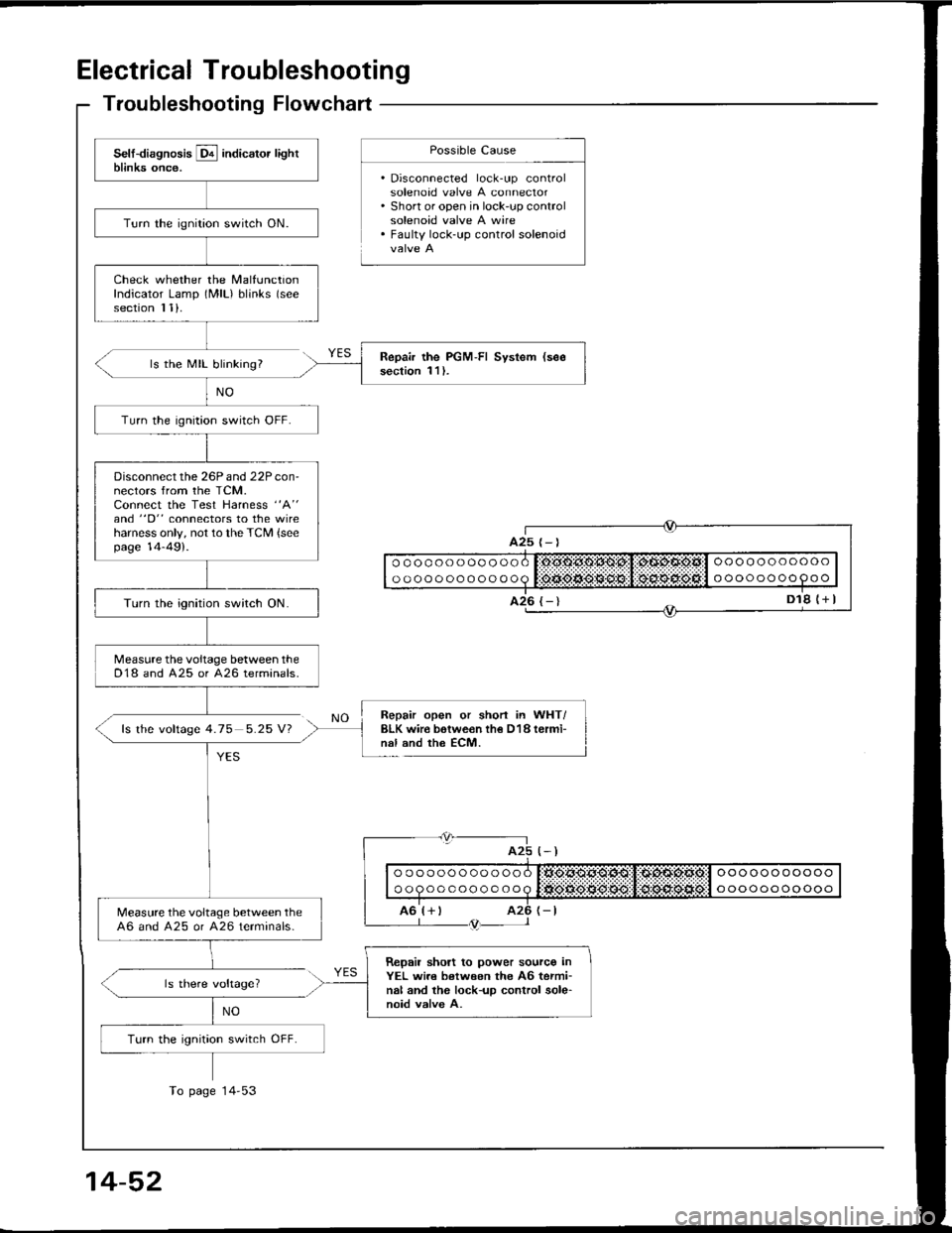
Electrical Troubleshooting
Troubleshooting Flowchart
ls the MIL blinking?
fs the voftage 4.75 5.25 V?
Possible Cause
. Disconnected lock-up controlsolenoad valve A connector. Short or open in lock-up controlsolenoid valve A wire. Faulty lock-up control solenoid
NO
YES
Repair open or shorl in WHT/BLK wir€ botwe€n th€ D18 termi-nal and the ECM.
(-)
| | o " q " " o o o o o o o q litigse.*grq$:,1:d:sd:siia:l " "" o " " o o oo " I
I ro'r+ r rz6 r-tL--- l /trtr-- l
ls there voltage?
NO
ooooooooooo
oooooooo9oo
oooooooooooo
oooooooooooo
A25
Turn the ignition switch ON.
Check whether the MalfunctionIndicator Lamp (MlL) blinks (see
section I 1).
Repair the PGM-FI System (see
section 1 l ).
Turn the ignition switch OFF.
Disconnect the 26P and 22P con-nectors from the TCM.Connect the Test Harness "A"
and "D" connectors to the wireharness only, not to the TCM {seepage 14-49).
Turn the ignition switch ON.
Measure the voltage between theD18 and A25 or 426 terminals.
Measure the voltage between the46 and A25 or A26 terminals-
Repail short to power sourco inYEL wi.e between the A6 termi-nal and the lock-up control sole-noid valve A.
Turn the ignition switch OFF.
To page 14'53
14-52
Page 445 of 1413
Me6sure the resistance betweenthe 46 and A25 or A26terminals.
Check for loos€ TCM connectors.It necessary, substitute a known_good solenoid valve assembly orTCM and recheck.
Repair short to ground in YEL wirobetween tho AG t€rminal and th€lock-uo control solsnoid valve A.
Ch€ck tor open in YEL wire bo-tween the A6 terminal and thelock-uD control solenoid valve A.ls the resistance 14- 16 0?
RoDlaca th6 lock-up control sol€-noid valv6 assembly.
Disconnect the 2P connector lromthe lock-up control solenoid valve
Check Ior continuitv between the46 and A25 or 426 terminals.
ls the resistance 14 16 O?
ls there continuity?
Measure lhe resistance of thesolenoid at the 2P connector.
{cont'd}
View lrom terminal side
14-53
Page 446 of 1413
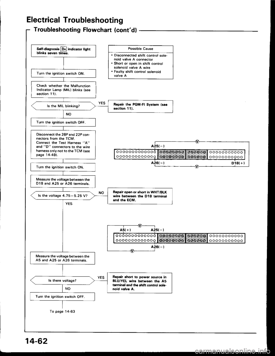
Electrical Troubleshooting
Troubleshooting Flowchart (cont'dl
Turn the ignition switch ON.
Check whether the MalfunctionIndicator Lamp (MlL) blinks (seesection 1 1).
Ropair tho PGM-FI Sysrom (se€soction 11).ls the MIL blinking?
Turn the ignition switch OFF.
Disconnect the 26P and 22P con-nectors trom the TCM.Connect the Test Harness "A"
and "D" connecto.s lo the wireharness only, not to the TCM (seepage 14-49).
Turn the ignition switch ON.
Measure the voltage between theD'18 and A25 or 426 terminats_
Rapair opon or shon in WHT/BLK wi.e botweon the O18 te.mi-nal rnd the ECM.
ls the voltage 4.75-5.25 V?
lvleasure the voltage between the44 and A25 or 426 rerminals.
Ropsir shon to power source inGRN/BLK wi.o betwoon the A4t6.minal and th€ lock-up controlsolonoid valve B.
Turn the ignition switch OFF.
14-54
Possible Cause
. Disconnected lock-up conlrolsolenoid valve B connector. Short or open in lock-up controlsolenoid valve B wire. Faulty lock up control solenoidvalve B
Page 447 of 1413
Measure the resistance betweenthe A4 and A25 or A26 terminals.
Check for looso TCM connocto.s.lf nocoasary, substitute a known-good solenoid valvo assombly otTCM and rochock.
is the resistance 14- 16 0?
Disconnect the 2P connector fromthe lock-up control solenoid valveassemory,
Check lor continuitv between theA4 and A25 or A26 terminals.
Ropair 3horl to Itound in GRN/BLK wir6 botwoon tho 44 totmi-nal and th6 lock-up cont.ol solo-noid valv6 B.
Measure the resistance ol thesolenoid at the 2P connector.
Chock lor opon in GRN/BLK wiiobotwaen tho A4 torminal and th6lock-up contrcl solonoid valvo B.ls the resistance 14- 16 07
R6Dlaco tho lock-up conttol 3016-noid valvs assembly.
2P CONNECTORView trom terminal side.
q
.UP CONTROLSOLENOID VALVEASSEMBLY
(cont'd)
14-55
Page 454 of 1413

Electrical Troubleshooting
S€ltdiagno3b Lql indicaror lighrblinks sovon timgs.
Turn the ignition switch ON.
Check whether the MalfunctionIndicator Lamp {MlL) blinks (seesection 11).
Ropai lhe PGM-FI Sysrem (so€Bection 1 11,ls the MIL blinking?
Turn th6 ignition switch OFF.
Disconnect the 26P and22P con-nectors from the TCM.Connect the Test Harness "A"
and "D" connectors to the wireharness only not to the TCM (seepage 14-49).
Turn the ignition switch ON.
Measure the voltage betw€€n theD18 and A25 or A26 lerminals.
Repair opon o. sho.t in WHT/BLKwire botwoon th€ D18 tarminaland the ECM.
fs the voftage 4.75-5.25 V?
Measure the voltage between theA5 and A25 or A26 terminals.
Ropair lhon to powor sourc6 inBLU/YEL wiro botwoon the A5torminal and th6 lhift control solo-noid valve A.
Turn the ignition switch OFF.
Troubleshooting Flowchart (cont'dl
Dl8( r I
Possible Cause
. Discohnected shift control sole-noid valve A connector. Short or open in shift controlsolenoid valve A wire. Faulty shill control solenoid
ooooooooooooooooooooooo
ooooo oooooooa t:tJio*ie*O:lt$!l $4lrulitEijt'l o oo oooooooo
Page 455 of 1413
{
oooooooooooo
ooooooooooooooooooooooo
oooooooooooMeasure the resistance betweenthe A5 and 425 or 426 terminals.
ls the resistance 14-16 0?
NO
3P CONNECTORView from terminal side.
SHIFT CONTROLSOLENOID VALVEASSEMBLY
(cont'd)
Chock lor loora TCM connectoE.lf n6c€53ary, sub3titut6 a known-good solonoid valvo assembly orTCM and r6check.
Disconnect the 3P connector tromthe shift control solenoid valve as-sembly.
Check for continuitv between theA5 and A25 or 426 torminals.
Ropair shon to ground in BLUI'ELwir6 botwoon tho A5 tstminal andtho shift conlrol solonoid valvo A.
Measure lhe resistance of thesolenoid at lhe 3P connector.
Check fo. opon in BLU/YEL wirobolween th6 A5 torminal and thoshift control solenoid valve A.
ls the resistance '14-16 0?
14-63