Page 410 of 1413
Description
Electronic Control System
Electronic Control System
The electronic control system consists of the Transmission Control Module (TCM), sensors. and 4 solenoid valves. Shift-
ing and lock-up are elect.onically controlled for comfortable driving under all conditions.
The TCM is located below the dashboard, behind the left side kick panel on the driver's side.
Lock-up ControlSolonoid Valvo A
14-18
Page 411 of 1413
Lock-up Control
From sensor input signals, the TCM determines whether to turn the lock-up
solenoid valve A and/or B accordingly.
The combination of driving siqnals to lock-up control solenoid valves A and
ON or OFF and activates lock-up control
B is shown in the table below.
Lock-up control Solenoid valve
B
Lock-up condition \
Lock-up OFFOFFOFF
Lock-up, slightONOFF
Lock-up. haltONON
Lock-up. fullONON
Lock-upduring decelerationONDuty operationOFF-ON
Shifl Conrrol
The TCM instantaneously determines which gear should be selected by various signals sent trom sensors. and actuates
the shift control solenoid valves A and B control shitting. Also. a Grade Logic Control System has been adopted to control
shifting in E] position while the vehicle is ascending or descending a slope, or reducing speed.
Shift control solenoid valve
t"*b" ,t"-l
------\B
E,E
('l st)OFFON
(2ndlONON
(3rd)ONOFF
E(4th)OFFOFF
a(2nd)ONON
tr (lst)ONOFF
l-Rl {Reverse)ONOFF
(cont'd)
14-19
Page 414 of 1413
Description
Electronic Control System {cont'dl
TH
SCI
scs
ECM
ACCL
AFSB
NEP LG1
LG2
*t-l
T777
sHtfT c0mRoL
SHFT COI{rFOLSOLINOIO VALVE B
TOCK-UPCONTROLSOLENOIOVALVE A
SPEEOSENSOF
COUNTE8SHAFISPEEOSENSORL_______.1tGcotLLOC( - UP CONTROLSOLENOIO VALVE B
f-r,'__lI Jll6 i
A/T CEAN POSITION INDICATOR
14-22
Page 415 of 1413
Hydraulic Control
The valve bodies include the main valve body, secondary valve body, regulator valve body, servo body and lock-up valve
body.
The oil pump is driven by splines behind the torque converter which is attached to the engine. Oil flows th.ough the
regulator valve to maintain specified pressure through the main valve body to the manual valve, directing pressure to
each of the clutches,
SHIFT CONTROL SOLEIIOIDVALVE ASSEMBLY
RTGHT SIDE COVER
LOCK.UP VALVE BODY
VALVE BODY
REGULATOR VBODY
SOLENOID VALVEASSEMBLY
4<.__i: )o.-
OIL PUMP GEARS
14-23
Page 416 of 1413
Description
Hydraulic Control (cont'dl
Ragularol Valve Body
The .egulator valve body is located on the main valve body. The regulator valve body consists of th€ regulator valva,
toroue converter check valve, cooler check valve, and lock-up contlol valve.
REGULATOR VALVE
REGULATOR VALVEBODY
COOLER CHECK VALVE
LOCT.UP CONTROI. VALVE
TONOUE COI{VERTEBCHECK VALVE
Lock-up Valvo Body
The lock-up valve body with the lock-up shilt valve and lock-up timing B valve is located on th€ regulator volvs body.
LOCK.UP SHIFT VALVE
TIMITG B VALVE
14-24
Page 417 of 1413

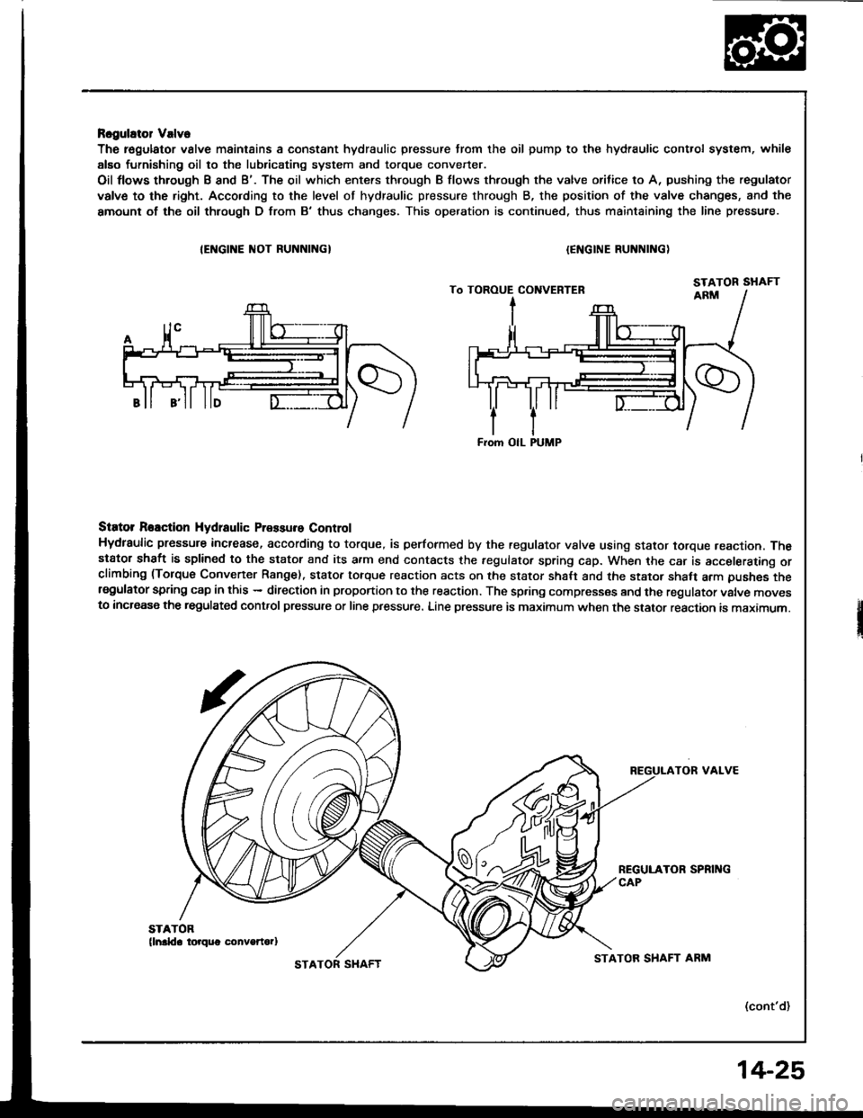
Rcgulator Valve
The r€gulator valve maintains a constant hydraulic pressure from the oil pump to the hydraulic control system, whil€
alEo furnishing oil to the lubricating system and torque convener.
Oil flows through B and B'. The oil which enters through B flows thfough the valve orifice to A, pushing the regulator
valve to the right. Acco.ding to the level of hydraulic pressure through B, the position of the valve changes, and the
amount of the oil thlough D from B'thus changes. This operation is continued. thus maintaining the line pressure.
IEI{GINE ]IIOT RUNNINGI{ENGINE RUNNING)
Siator Reaction Hydtaulic Pressure Control
Hydraulic pressure increase, according to torque, is performed by the regulator vslve using stator torque reaction. Thestator shaft is splined to the stator and its a.m end contacts the fegulator spring cap. When the car is accelerating orclimbing (Torque Convener Range). stator torque reaction acts on the stator shalt and the stator shaft arm pushes thersgulator spring cap in this - direction in proportion to the reaction. The spring compresses and the regulator valve movesto increase the regulated control pressure or line pressure. Line pressure is maximum when the stator reaction is maximum.
TOR VALVE
(cont'd)
From OIL PUMP
STATOR SHAFTSTATOR SHAFT ARM
14-25
Page 418 of 1413
Description
Hydraulic Control (cont'dl
Main Valvo Body
The manual valve, 1-2 shift valve, 2-3 shift valve. 4th exhaust valve. CPC valve, and relief vatve are all assembled inthe main valve body,
The primary function of this valve body is switching oil passages on and off and controlling the hydraulic pressure gotngto the hydraulic control system.
4TH EXHAUST VALVECPC VALVE
RELIEF VALVE
MANUAL VALVEMAIN VALVE BODY
S€condary Vslve Body
The secondary valve body is located on the main valve body. The 3-2 kick-down valve, 4-3 kick-down valve. 2-3 orificecontrolvalve. orifice controlvalve, 3-4 shift valve, modulator valve, and servo control valve are assembled in the secon-da.y valve body.
ORIFICE COIITROLVALVE2-3 ORIFICE CONTBOL VALVE
3.4 SHIFT VALVE
VALVE BODY
MOOULACOITTROL VALVE
1.2 SHIFT VALVE
14-26
Page 419 of 1413
S6rvo Body
The servo bodv is located on the secondary valve body.
The servo valve is integrated with the shiit fork shatt, throttle valve B. and accumulator pistons, which are all assembled
in the servo bodv.
SERVO VALVE/SHIFT FORK SHAFT
THROTTLE VALVE BSERVO BODY
Accumulator Pislons
The accumulator pistons are assembled in the servo body and right side cover. The l st-hold clutch accumulator piston
is in the right side cover, and the 1st, 2nd 3rd, and 4th accumulator pistons are assembled in lhe servo body.
RIGHT SIDE COVER
THROTTLE LONG VALVE
1ST-HOLD ACCUMULATOR
4TH ACCUMULATOR
IST ACCUMUI-ATOR
2ND ACCUMULATOR PISTON3RD ACCUMULATOR PISTON
14-27