Page 268 of 1413
System Description
The idle speed ot lhe engine is controlled by the ldle Air Control {lAC) Valve.
The valve changes the amount ot air bypassing into the intake manifold in response to electric current controlled by the
ECM. When the IAC Valve is activated, the valve opens to maintain the proper idle speed.
#l' ----rTo FGM-FIMAINRELAY
VARIOUSSENSORS
IAC VALVE
FASTIDLETHERMOVALVE
INTAKE MAI{IFOLD
(cont'd)
BLK
r
11-79
Page 269 of 1413
ldle Control System
System Description (cont'd)
1 . Atter the engine slarts. the IAC valve opens for a censin time, The amount ot air is increased to raise the idle soeedabout 15O-3OO rom.
2. When the coolant temperature is low, the IAC valve is opened to obtain the proper fast idle speed. The amount ofbypassed air is thus controlled in relation to the engine coolant temperature.
IDI-E SPEEDlrpm)
176
80
ENGINECOOLANT TEMPERATURE
t"Fl(oct
11-80
Page 270 of 1413
1. when the idls speed is out of specification and the Malfunction Indicator Lamp (MlLldoes not blink Diagnostic Trou-
ble Code (DTC) 14, check the tollowing items:. Adiust the idle speed {see page I1-95). Air conditioning signal (see page l1-84). ALT FR signal (see page '11-86)
A/T gea, position signal (see page 11-88)
Erake switch signal (see page 1 1-90)
Starter switch signal (see page 1l-921
PSP switch signal (see page 1 1-93)
Fast idl6 thormo valve (see page l1-94)
Hoses and connsctions
IAC valve and its mounting O-rings
2. lf the above items are normal, substitute a known-good IAC vslv€ and readjust the idle speed (see page 11-95)'
. It the idle speed srill cannot be adjusted to speciJication (and the MIL does not blink code 14) after IAC valve
roplacement, substitute a known-good ECM and recheck. It symptom goes away, replsce the original ECM.
1 1-81
Page 271 of 1413

ldle Control System
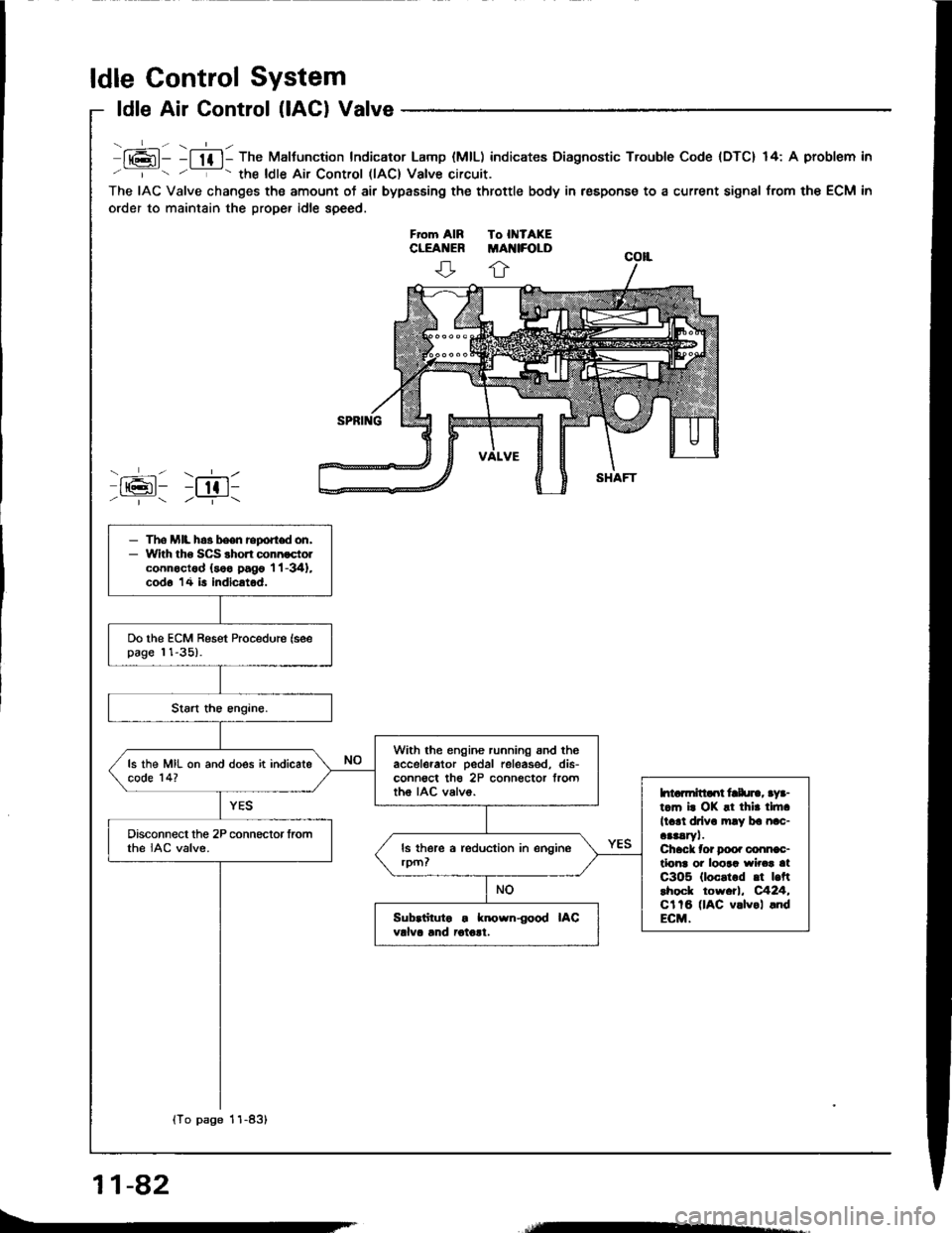
ldle Air Control (lACl Valve
lt6l- -l lf l- The Maltunction Indicator Lamp (MlL) indicates Diagnostic Trouble Code {DTC} 14: A problem in
' '- the ldle Air Control llAC) Valve circuit.
The IAC Valve changes the amount of air bypasEing the throttle body in respons€ to a current signal from the ECM in
order to maintain the proper idle speed.
ffi: r;611/ | /--T-\
- The MIL h.3 been report don,- With tho SCS shon connoctolconnoctod (soo pago 'l 'l -341,
cod6 14 is indicatod.
Do the ECM Reset Procedure (seepage 11-35).
With the engine running snd theaccelerator pedal releas€d, dis-conn€ct th€ 2P connector frorttho IAC valvo.
ls the MIL on and does it indicatecode 14?
htarmitlaot frlu]., aya-t.m i. OK !t thir tlft.
ll.rl drlv. mly ba nac-aaaaryl.Chack tor Doo. conn€c-tlonr oi loora wirca atC3O5 (loc.t.d .t |.ftlhock tow.tl, C424,Cl tB (lAC v.lvol .ndECM.
Disconnect the 2P connector fromthe IAC valve.
Sub.iituto . known{ood IACvdva lnd iotolt.
{To page 11-83}
11-82
Page 272 of 1413
(From page 'l 1-82)
Measure voltago between theYEL/BLK wire and bodv ground.
R.pair op.n In YEL/8LK who b.-twoon IAC vCvc dd PGM-FI mdnrelay.ls th€rs battery voltage?
Turn th€ ignition swirch ott andreconnect thg 2P cohnector to theIAC valve.
Conn€ct the test hs.ness "A"
connector to the main wirs hrr-n6ss only, not the ECM lsee page
t 1-37).
Tu.n tho ignition switch ON.
Momentarily connect Ag torminalto 423 terminol seveaal tim€s.
Sub.titutr ! known{ood ECM.nd ral..t. lt .ymptom/hdlcatioogoa! awsy. rophca tia origlnalECM.
Does th6 IAC valve click?
Raplir op.n or rhort in 8LK/BLUwl]. b.tw.cn IAC v!lv..nd ECM(A91, It th. wlro L OK, r.Dhc.lheIAC v.lv..
IAC VALVEBLK/BLU { _ }
JUMPER WIRE
A9 l+) A23 {-l
1 1-83
Page 283 of 1413

ldle Control System
Fast ldle Thermo Valve
DEscliptlon
To prevent erratic running when the engine is warming
up, it is n€cessary to raise the idle speed. The fast idle
thermo valve is controlled by a thermowax plunger, When
the engine is cold. the engine coolant su.rounding the
thermowax contracts the plunger, allowing additional air
to be bypassed into the intake manifold so that the en-
gine idlss taster. When the engine reaches operating tem-
peratur€, the valve closss, reducing the amount of air
bypassing into the manifold.
FAST IDLE THERMOVALVE
AIN EYPASS VALVE
Inspaction
NOTE: The tast idle thermo valve is factory adiustsd;
it should not be disassombl€d.
1. Remove the intake air duct from the throttlg body.
2. Stan the engine.
3. Put your finger over ths lower port in throttle body
and make sure that there is 8ir flow with tho engine
cold (engine coolant temperatute below 86oF,
300c).
a lf not,
retest.
leplace the fast idle thermo valvs and
4.
o-Rr{GsReplace
llo kgf.m, 7 lbt.trl
Start the engine. Hold the sngine at 3.0OO rpm with
no load (A/T in I or @ position, M/T in neutral]
until the radiator fan comes on, then let it idl6.
Check thst valve is completely closed. lt not, air suc-
tion can be telt at the lower Don in the throttle body,
a It any suction is felt, the valve is leaking Check
engine coolant level and for air in tho engine
coolant system (see section 1O). ll OK, rsplace
the fast idle thermo valve and rechock.
11-94
Page 284 of 1413

- ldle Speed Setting
Inspoction/Adiustment
NOTE:
a When the idle speed set, check the following items:
- The MIL has not been reported on.- lgnition timing- Spark plugs- Air cleaner- PCV svstem
a (Canada) Pullthe parking brake lever up. Stan the en-
gine, then check that the headlights are off.
1 Start the engine. Hold the engine at 3,000 rpm with
no load (A/T in S or @ position, M/T in neutral)
until the radiator tan comes on, then let it idle.
2. Connect a tachometer.
3. Disconnect the 2P connectot trom the ldle Air Con-
trol {lAC) valve.
Start the engine with the sccelerator pedal slightly
depressed. Stabilize the rpm at 1 ,OOO, then slowly
release the pedal until the engine idles.
Check idling in no-load conditions: headlights, blower
fan, rear defogger, radiator fan, and ai. conditioner
are not operatrng.
ldl€ spood should bo;
81881 ongino:
MlT48O ! 50 rym
An48O I 50 rpm
lin@or@oosition)
818C7 engine:48O ! 50 rym
Adjust the idle speed, if necessary, by turnmg the
idle adiusting screw.
NOTE: After adiust the idle speed in this step, check
the ignition timing (see section 231.
lf it is out ot spec. go back to step 4.
4.
e
Turn the ignition switch OFF.
Reconnect the 2P connector on the IAC valve, then
remove the BACK UP (7.5 A) fuse in the under-hood
tuse/relav box for 1O seconds to reset the ECM.
Restart 8nd idle the engine with no-load conditions
for one minute, then check the idle speed.
NOTE: (Canada) Pull the parking brake lever up.
Start the engine, then check that the headlights ate
off.
ldlo speed should be;
81881 ongino:
MTf75O ! 50 rpm
AIT75O t 50 rpm
(in[]or@positionl
818C1 engine: 750 1 50 rpm
(cont'd)
11-95
Page 291 of 1413

Fuel Supply System
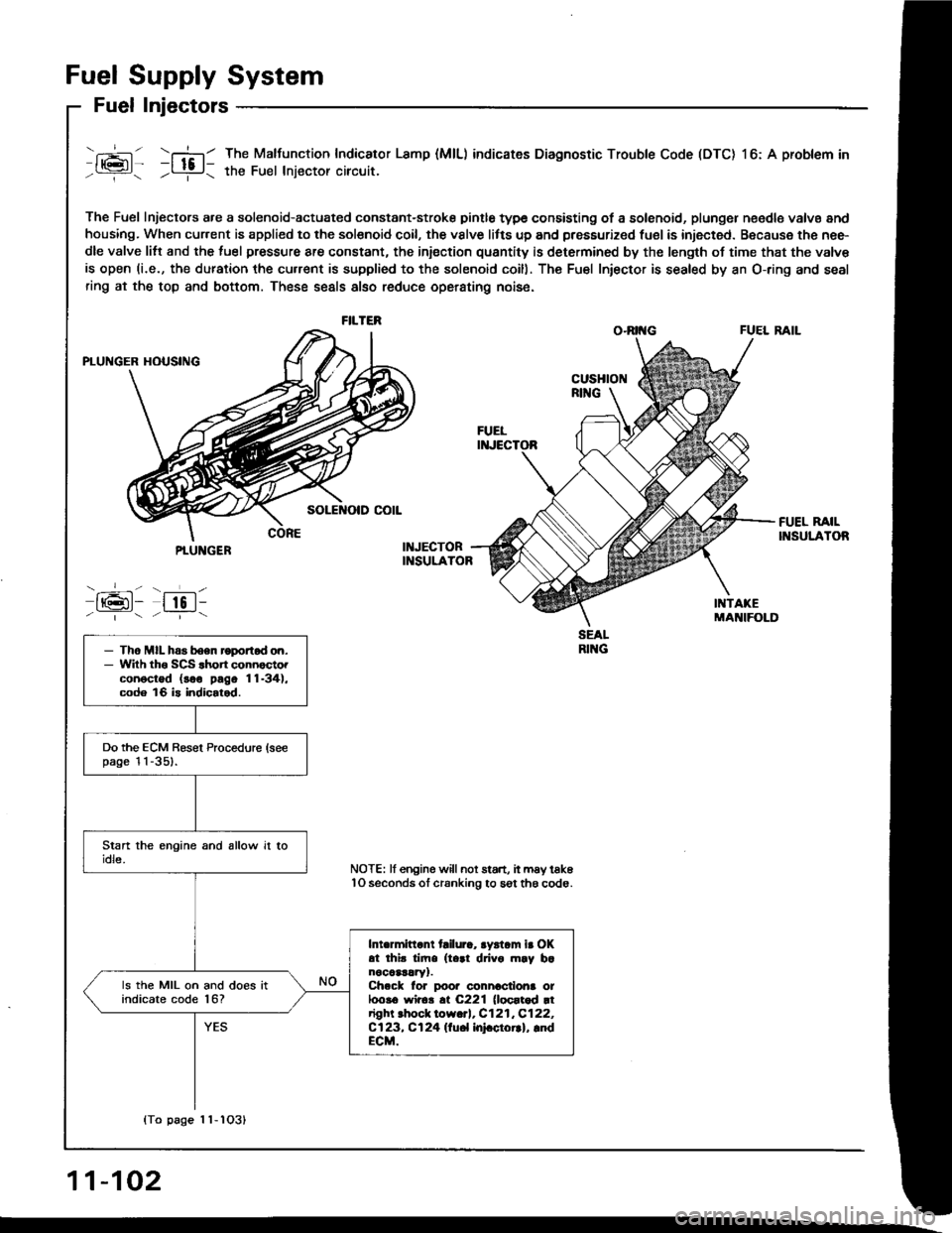
Fuel Injectors
- --l- - \-l-l
116l- -ltc l-/---r- / ---i- \
The Fuel Injectors a.e a solenoid-actuated constant-stroke pintle type consisting of a solenoid, plungel n€edle valvs and
housing. When cur.ent is applied to the solsnoid coil, the vslve litts up and pressurized fuel is injected. Because the nee-
dle valve litt and the luel pressure are constant, the iniection quantity is determined by the length of time that the valv€
is open (i.e., the duration the cu.rent is supplied to the solenoid coill. The Fu€l Iniector is sealed by an O-ring and seal
ring at the top and bottom. These seals also reduce operating nois6.
O.RII{G FUEL RAIL
The Malfunction Indicator Lamp (MlL) indicates Diagnostic Trouble Code (DTC) l6: A problem in
the Fuel lniector circuit.
FILTER
PTUNGER
-_-- - ___L-
IrGl- lto l--|.---:_-
- Tho MIL has boen roportod on.- Wilh tho SCS .hon connocto.conoctod (soo pago 11-34),code 16 is indicalod.
Do the ECM Besel Procedure (seepage l l -351.
Intermittant tailura, aystam ir OKat thir tim. (t..1 drivo m.y b.nocaar!ry1.Ch.ck lor poor connactiona ot100!6 wir6!.t C221 (loortod rtright .hock low.rl, C121,C122,Cl23, Cl24 llu6l InFctorrl, lndECM.
ls the MIL on and does itindicate code l6?
NOTE: lf engine willnot start, it may tak6lO seconds ol cranking to sgt th6 code.
{To page 1 1-1O31
11-102