1994 ACURA INTEGRA Valve
[x] Cancel search: ValvePage 456 of 1413

Electrical Troubleshooting
Troubleshooting Flowchart (cont'dl
Possible Cau6e
. Disconnected shift control sole-noid valve B connector. Short or open in shift controlsolenoid valve B wire. Faulty shilt control solenoidvalve B
Solfdiagnolir [!4 Indicato. lightbllnk! eight tim6r.
Turn the ignition switch ON.
Check whother the MalfunctionIndicator Lamp {MlL) blinks (seesection I 11.
Rcpsir rho FGM-FI Syrtem lso6scciion l1l.ls the MIL blinking?
Turn the ignition swirch OFF.
Oisconn€ct the 26P and 22P con-nectors trom the TCM.Connect the Test Harness "A"
and "D" connectors to the wirohamess only. not to the TCM {sesp6ge 14-49).
Turn the ignition switch ON.
Measure the voltage betwe€n theD18 and A25 or A26 terminals.
Ropeir opon or short in WHT/BLKwiro trotweon th6 D18 termineland tho EcM.
ls the voltage 4.75-5.25 V?
Measure the voltage between th€A3 and A25 or A26 terminals.
Ropair rhort to powor rourco inGR /WHT wir6 b€twgan tho A3tormirEl and shift conLol lolonoidvalve B.
Turn the ignition switch OFF.
A2s( - |
DlA( + I
o oooooooooo
ooooooooooooo oo ooo ooooo
oooo o o oo
To page
Page 457 of 1413
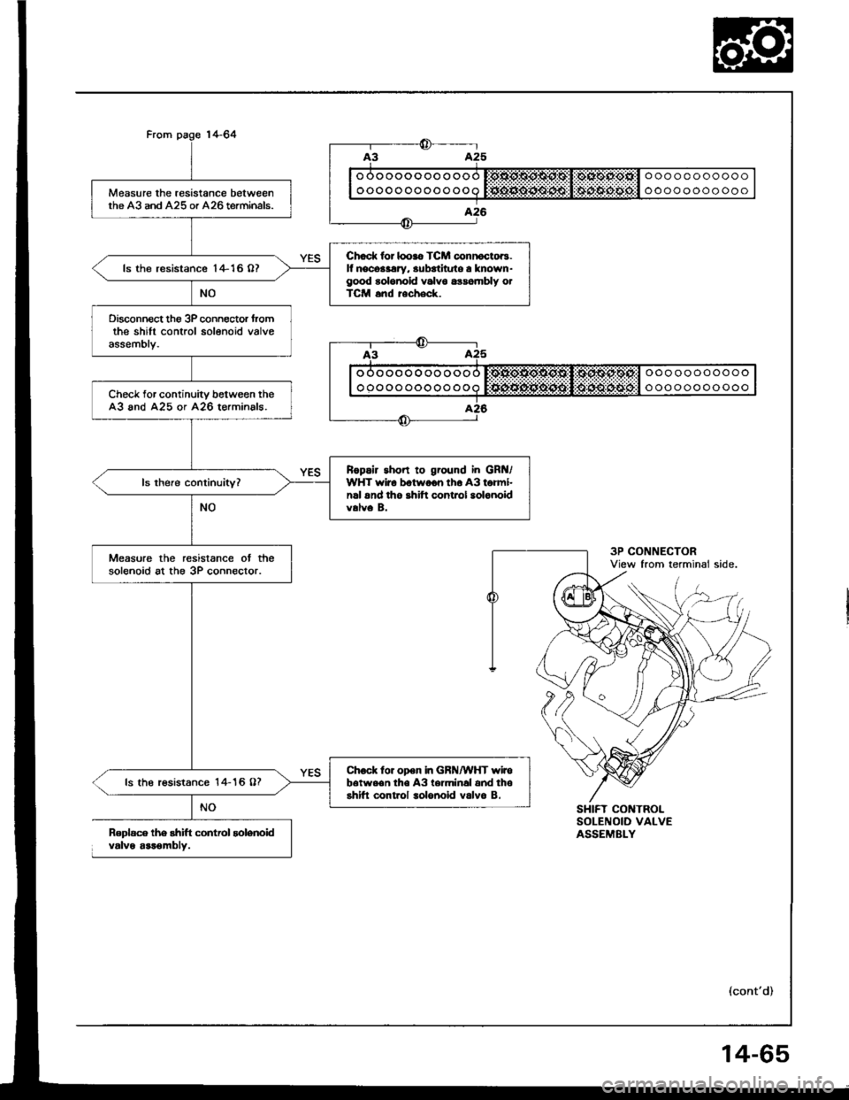
Measure the resistance betweenthe A3 and A25 or A26 terminals.
Chod. lor looro TCM connoctoB.lf nocdaary. 3ubatltute a known-good rolonold valv6 6ra6|nbly otTCM snd recheck.
ls the resistance I +16 07
Disconn€ct th6 3P conngctor fromthe shift control solenoid valveassembly.
Check for continuity between theA3 and A25 or A26 terminals.
Ropair short to ground in GRt{/WHT wiro botwoon th6 A3 tormi-nrl and tho shitt control aolonoidvalve B.
Measure the resistance ot thesolenoid at the 3P connector.
Chock to. open in GRN/WHT wirob6twe.n th€ A3 lerminal and thoshifl control solonoid valvo B.ls the r€sistance 14- 16 O?
oooooooooooo
oooooooooooo
ooooooooooo
ooooooooooo
Roplace lhe rhift control solenoidvalve arr€mblv.
SHIFT CONTROLSOLENOID VALVEASSEMELY
(cont'd)
14-65
Page 474 of 1413
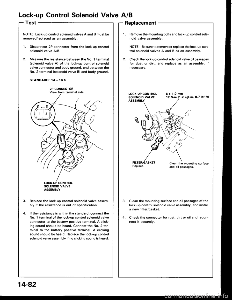
Lock-up Control Solenoid Valve A/B
NOTE: Lock-uD control solenoid valves A and B must be
removed/replaced as an assemblv.
l. Disconnect 2P connector trom the lock-uo control
solenoid valve A/8.
2. Measure the resistance between the No. 1 terminal(solenoid valve A) ot the lock-up cont.ol solenoid
valve connector and body ground, and between the
No. 2 terminal (solenoid valve B) and body ground.
STANDARD: 14- 16 O
2P CONI{ECTORView trom terminal side.
SoLENOTO VAI-VEASSEMBLY
Reolace the lock-uo control solenoid valve assem-
bly if the resistance is out of specitication.
lf the .esistance is within the standard, connect the
No. 1 terminal ot the lock-uo control solenoid valve
connector to the battery positive terminal. A click-
ing sound should be heard. Connect the No. 2 ter-
minal to the battery positive terminsl. A clicking
sound should be heard. Replace the lock-up control
solenoid valve assembly if no clicking sound is heard.
?
4.
Replacement
Remove the mounting bolts and lock-up control sole-
noid valve assembly.
NOTE: Be sure to remove or replace the lock-up con-
trol solenoid valves A and B as an assembly.
Check the lock-up control solenoid valve oil passages
tor dust or dirt. and replace as an assembly, if
neceSsary.
6 x 1.0 mm12 N.m (1.2 kgf.m,8.7 lbf'ft)
Clean the mounting sudaceand oil passages.
Clean the mounting surtace and oil passages of the
lock-up control solenoid valve assembly. and install
a new filter/gasket.
Check the connector for rust, dirt or oil and recon-
nect rt securely.
14-82
Page 475 of 1413
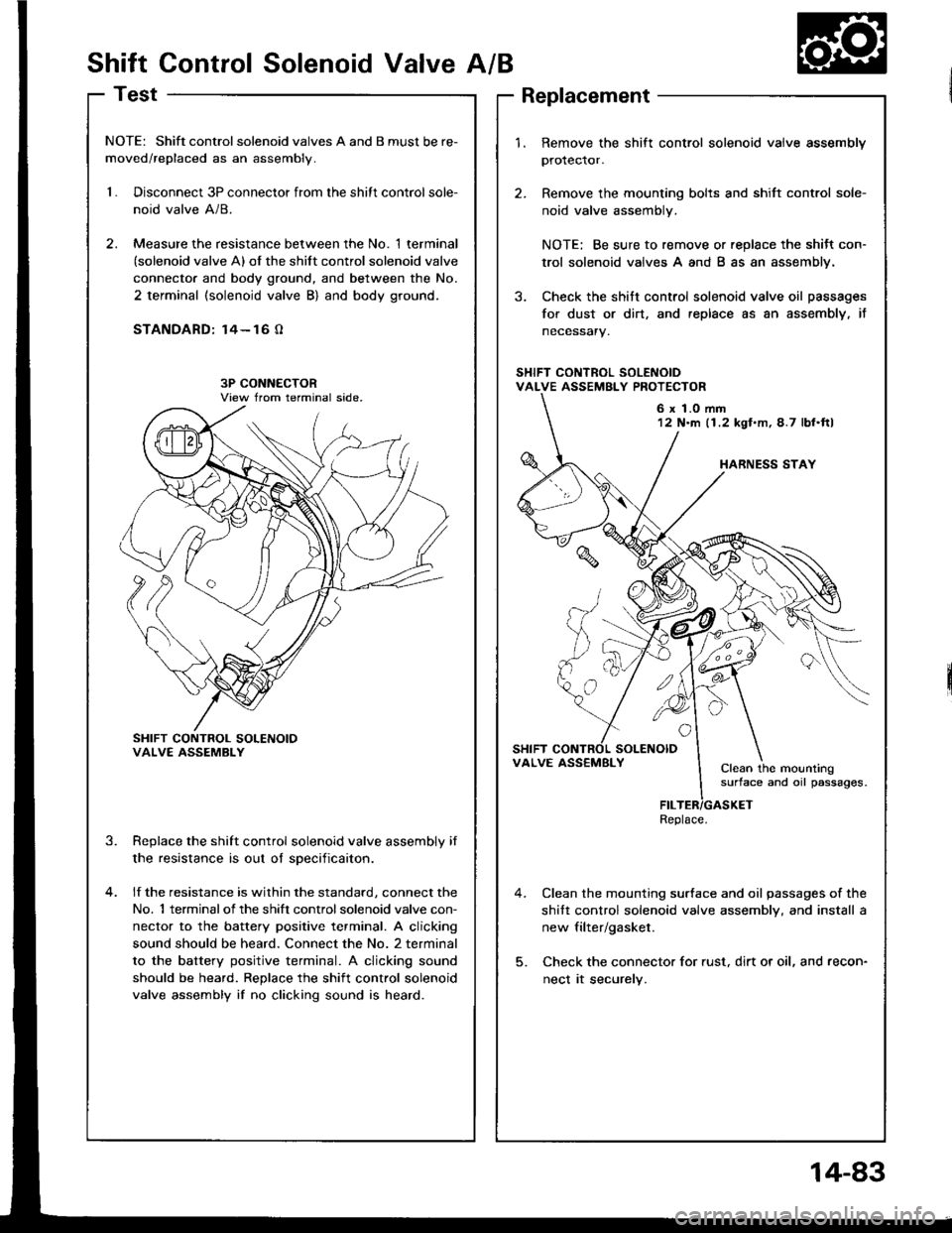
Shift Control Solenoid ValveA/B
Test
NOTE: Shift controlsolenoid valves A and B must be re-
moved/replaced as an assembly.
1.Disconnect 3P connector from the shitt control sole-
noid valve A/8.
Measure the resistance between the No. 1 terminal(solenoid valve A) of the shift control solenoid valve
connecto. and body ground, and between the No.
2 terminal (solenoid valve B) and body ground.
STANDARD: 14- 16 O
SHIFT CONTROL SOLENOIOVALVE ASSEMBLY
Replace the shift control solenoid valve assembly if
the resistance is out oI sDecificaiton.
lf the resistance is within the standard, connect the
No. 1 terminalof the shift controlsolenoid valve con-
nector to the battery positive terminal. A clicking
sound should be heard. Connect the No. 2 terminal
to the battery positive terminal. A clicking sound
should be heard. Replace the shift control solenoid
valve assembly if no clicking sound is heard.
3.
1.Remove the shift control solenoid vaive assembly
protector.
Remove the mounting bolts and shift control sole-
noid valve assembly.
NOTE: Be sure to remove or replace the shitt con-
trol solenoid valves A and B as an assembly.
Check the shitt control solenoid valve oil passages
for dust or dirt, and replace as an assembly, it
necessary.
Clean the mounting surface and oil passages of the
shitt control solenoid valve assembly, and install a
new filter/gasket.
Check the connector for rust, dirt or oil, and recon-
nect it securely.
6 x 1.0 mm12 N'm (1.2 kgl.m,4.7 lbl.ftl
VALVE ASS€MBLYClean the mountingsurface and oil passages.
Replace.
14-83
Page 479 of 1413
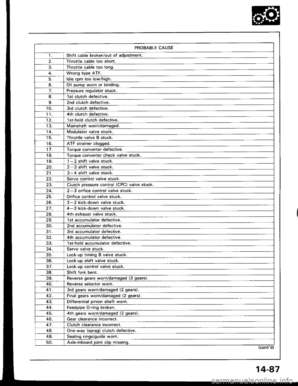
PROBABLE CAUSE
1Shitt cable broken/out of adiustment.
Throttle cable too short.
Throttle cable too long.
Wrong type ATF.
ldle rpm too low/high.
o.Oil pump worn or binding.
7.Pressure regulator stuck.
8.l st clutch detective.
9.2nd clutch detective.
10.3rd clutch defective.
114th clutch defective.
12.1 st'hold clutch defective.
13.Mainshatt worn/damaged.
14.Modulator valve stuck.
Throttle valve B stuck.
lo.ATF strainer clogged.
Toroue converter def ective.
18.Torque converter check valve stuck.'I 9.1-2 shift valve stuck.
2-3 shift valve stuck.
213-4 shift valve stuck.
Servo control valve stuck.
23.Clutch Dressure control (CPC) valve stuck.
2-3 orifice control valve stuck.
Orifice control valve stuck.
26.3-2 kick-down valve stuck.
27.4-3 kick-down valve stuck.
24.4th exhaust valve stuck.
29.1st accumulator detective.
30.2nd accumulator detective.
313rd accumulator defective.
4th accumulator defective.
1 st-hold accumulator defective.
Servo valve stuck.
35.Lock-up timing B valve stuck.
36.Lock-up shift valve stuck.
37.Lock-uo control valve stuck.
38.Shift fork benr.
39.Reverse gears worn/damaged (3 gears).
40.Reverse selectot worn.
413rd gears worn/damaged (2 gears).
Final qears worn/damaged (2 gearsl.
43.Differential Dinion shatt worn.
44.Feedpipe O-ring broken.
45.4th qears worn/damaged (2 gearsl
Gear clearance incorrect.
47.Clutch clearance incorrect.
48.One-way (sprag) clutch defective.
49.Sealinq rings/quide worn.
50.Axle-inboard joint clip missing.
Page 480 of 1413
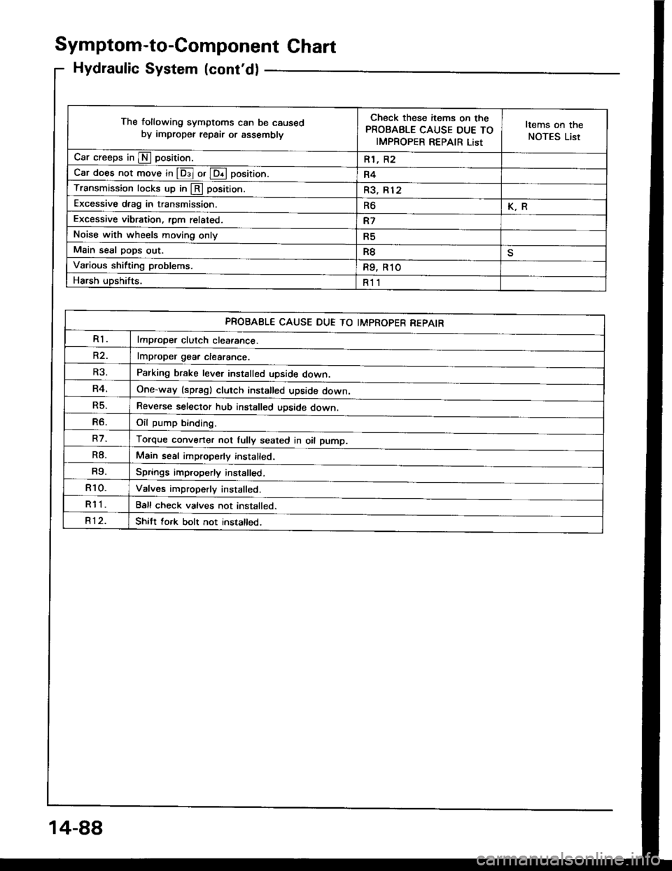
Symptom-to-Component Ghart
Hydraulic System (cont'd)
The following symptoms can be caused
by improper repair or assemblv
Check these items on the
PROBABLE CAUSE DUE TO
IMPROPER REPAIR List
Items on the
NOTES List
Car creeps in E position.R1, R2
Car does not move in @ or @ position.R4
Transmission locks up in @ position.R3, Rl2
Excessive drag in transmission.R6K.R
Excessive vibration, rom related.R7
Noise with wheels moving onlyR5
Main seal pops out.R8
Various shifting problems.R9, R1O
Harsh upshifts.R11
PROBABLE CAUSE DUE TO IMPROPER REPAIR
R1lmproper clutch cleatance.
R2.lmDroDer qear clearance.
Parking brake lever installed upside down.
One-way (spragl clutch installed upside down,
Reverse selector hub installed upside down.
Oil oumo bindind
Torque converter not fully seated in oil pump.
Main seal improperly installed.
Springs improperly installed,
Valves improperly installed.
Ball check valves not installed.
Shitt fork bolt not installed.
R3.
R4.
R5.
R6.
R7.
R8.
R9.
R10.
R11
R12.
14-88
Page 481 of 1413

NOTES
A.See flushing procedure, page l4-168 and 169.
B.Set idle rpm in gear to specitied idle speed. lf still no good, adiust motor mounts as outlined in engine
section of service manual.
lf the large clutch piston O-ring is broken, inspect the piston groove for rough machining.
lf the clutch pack is seized or is excessively worn, inspect the other clutches Jor wear, and check the
orifice control valves and throttle valves for free movement.
E.It throttle valve B is stuck, inspect the clutches for wear.
lf the 1-2 shift valve is stuck closed, the transmission will not upshift. lI stuck open, the transmission
has no lst gear.
H.lf the 2-3 orifice control valve is stuck, inspect the 2nd and 3rd clutch packs for wear.
ll the orifice cont.ol valve is stuck, inspect the 3rd and 4th clutch packs for wear.
lf the clutch Dressure control valve is stuck closed, the transmission will not shilt out of 1st gear.
K.improper alignment or main valve body and torque converter housing may cause oil pump seizure. The
symptoms ale mostly an rpm-related ticking noise or a high-pitched squeak.
L.ll the ATF strainer is ctogged with panicles of steel or aluminum, inspect the oil pump and ditferential
pinion shaft. lt both are OK and no cause lor the contamination is found, replace the torque converter.
M.lf the 1st clutch feedpipe guide in the right side cover is scored by the mainshaft, inspect the ball bear-
ing for excessive movement in the transmission housing. lf OK. replace the right side cover as it is dent-
ed. The O-ring under the guide is probably worn.
N.ReDlace the mainshstt if the bushing for the 4th feedpipe is loose or damaged.
It the 4th feedpipe is damaged or out ot tound, replace the right side cover'
Replace the subjshaft it thtbushing for the 1st-hold Jeedpipe is loose or damaged.
lf the 1st-hold feedpipe is damaged or out of round, replace it.
Replace the mainshaft if the bushing lor the 1st feedpipe is loose or damaged.
lf the lst feedpipe is damaged or out ot round, replace it.
o.A *o- r, da."s"d "p-g clutch is mostly a result of shifting the transmission in El or Lq! position
while the wheels rotate in reverse, such as rocking the car in snow.
P.InsDect the frame for collision damage.
o.Inspect for damage or wear:
1. Reverse selector gear teeth chamfers.
2. Engagement teeth chamters of countershaft 4th and reverse gear.
3. Shift fork for scutt marks in center.
4. Differential Dinion shaJt for wear under pinion gears.
5. Bottom of 3rd clutch for switl marks.
Replace items 1 , 2, 3 and 4 it worn or damaged. lf transmission makes clicking, grinding or.whirring
noise, atso replace mainshaft 4th gear and reverse idler gear and countershaft 4th gear in addition to
1,2,3ot4.lf ditiersntial Dinion shaft is worn, overhaul differential assembly, and replace ATF strainel, and thoroughly
clean transmission, tlush torque convertet, cooler and lines.
lf bottom of 3rd clutch is swirled and transmission makes gear noise, replace the countershaft and tinal
driven gear.
R.Be wry careful not to dsmage the torque converter housing when replacing the main ballbearing. You
may al;o damage the oil pump when you torque down the main valve body. This will result in oil pump
seizure it not detected. Use proper tools.
qInstall the main seal tlush with the torque converter housing, lf you push it into the torque converter
housing until it bottoms out. it will block the oil return passage and result in damage.
T,Harsh do\/vnshiJt"\./l,'hen coasting to a stop with zero th.ottle may be caused by a bent-in throttle valve
retainer/cam stopper. Throttle cable adjustment may clear this problem.
ifuitle cable adjustment is essential for proper operation of the transmission. Not only does it affect
the shift points if misad,usted, but also the shift quality and lock-up clutch operation'
A cable adjusted too long will result in throttle pressure being too low for the amount of engine torque
input into ihe trsnsmission and may cause clutch slippage. A cable adjusted too short will result in too
hi;h throttle pressure which may cause harsh shitts, erratic shrfts and torque con
14-89
Page 483 of 1413

Throftle OpeningUnit of spe6dl st- 2nd2nd-3rd3rd-4th
Throttle position sensorvoltage: O.7 5 V
mph20-2227,30
Km/h17,O 19.O32.5 - 35.543.5-48.5
Throttle position sensorvoltage: 2.5 V
mpn
Km/h33.5 - 36.557.O-63.O89.O-95.O
Full-opened throttlemph30- 3462-6598- 101
Km/h49.O- 55.O99.O- 105.O1 57.O- 163.O
@ or @ Position
. Upshitt
Downshift
LOCK-Up
4. Accelerate to about 35 mph {57 km/h) so the transmission is in 4th, then shift from @ Oosition to E position.
The car should immediately begin slowing down from engine braking.
CAUTION: Do not shift from @ or @ position to @ of E position at speeds over 1OO mph (160 km/h); you
may damage the tlansmission,
5. Check lor abnormal noise and clutch slippage in the following positions.
E (1st Gear) Position- 1 . Accelerate from a stop at full throttle. Check that there is no abno.mal noise or clutch slippage.
-2. Upshifts should not occur with the selector in this position
E (2nd cear) Position.- 1 . Accelerate from a stop at full throttle. Check that there is no abnormal noise or clutch slippage.-2. Upshitts and downshitts should not occur with the selector in this position.
E {Reverse) Position
Accelerate from a stop at full throttle, and check for abnormal noise and clutch slippage.
6. Test in E {Parking) Position
Park car on slope (approx. 1 6o ), apply the parking brake, and shift into LE position. Release the brake; the car should
not move.
i
Throttle Op€ningUnit ot speed4th- 3rd3rd - 2nd2nd- l Et
Full-closed throttlemph1a-216-g (3rd- 1st)
Km/h29.O-33.O1O- 14 (3rd- lst)
Full-opened throttlemph85-8954- 5823-27
Km/h1 37.O- 143.08 7.0 - 93.037.0-43.O
Throttle OpeningUnit of speed
@ Position
Lock-uo control solenoidvalve A ON
Lock-up control solenoidvalve B ON
Throttle position sensorvoltage: 2,5 V
mpntJ- to17 -20
km/h21.O- 25.O2A.O-32.O
Full-opened throttlempn92-9692-96
km/h148.O - 1 54.0r 48.0,1 54.O
Throttlo OpeningUnit of sp6edE Position
Lock-up control solenoidvalve A ON
Lock-up control sol€noidvalv6 B ON
Throttle position sensorvoltage: 1.O Vmphb|-oJ61 63
kmih98- 10298- 102
Full-opened throttlemph85 8985-89
km/h137 143137 - 143
14-91