Page 129 of 156

Downloaded from www.Manualslib.com manuals search engine DO-lT-YOURSELF
Installing radio
When service installing a radio or replacing
a set installed by the factory the following
points should be noted
• The connection "
in the vehicle is for
Genuine Volkswagen radiosll from Model Year 1994.
• Radios with oth er con nections must be
connected with a n adapter cab le which can also be obtained from a Volkswagen dealer.
Attention On no account cut wires off and leave them without insulation. If necessary use a proper adapter. Otherwise the wiring can be overloaded or short circuits can occur -Fire danger!
11 Not availab le i n all export mark ets
Apart from this, important electronic components can be damaged or the functioning impaired. If for example the speed signal is disturbed this can lead to faulty engine management, automatic gearbox, ABS etc.
Even connecting the speed signal to radio sets with speed dependent volume control from other manufacturers can cause such faults.
• It is advisab le therefore to have the in
sta llation of the radio system done by a Volkswagen dealer. They are fully informed
about the technical features of the vehicle,
have the Genuine radios
1), the necessary
fitting parts from the Genuine Volksvvagen
Accessory Programme 1
) and work in ac
cordance with the guidelines developed by
the factory . •
The radios from the Genuine Volk
swa gen Accessory Programme
1
) are similar
to those used in the factory and ensure
trouble-free Installation .
These sets are
in keeping with the advanced technology and well-planned easy
to-operate design.
In Germany there is also an Exchange Ser
vice for the se radios so that even after years
of use a set requir ing repair
can be ex
changed cheaply for a completely recondi
tioned, good-as-new set by a Volkswagen
dealer.
• Loudspeakers, fitting parts, aerials and
supp
ression kits shou ld also be taken from
the Genuine Volkswagen Accessory Pro
gramme1) These parts have all been
specially developed for each vehicle model.
127
Page 130 of 156

Downloaded from www.Manualslib.com manuals search engine ----DO-lT-YOURSELF
Emergency starting
A -Flat battery
B - Boosting battery
The battery
is located in the engine com
partment.
I f the engine will not start because the bat
tery is flat.
jumper cables can be con
nected to the battery of another vehicle to
start the engine . The follow ing points
should be noted
• Both batteries
must be of the 12 Volt var
iety and the capacity (Ah) of the booster bat
tery must be app roximately the same as that of the flat battery .
• The jumper cables must be heavy
enough to carry the load. Note cable manu
facture r's data. •
Only use Jumper cabl
es with insulated
clips.
• A flat battery
can freeze at -1 Ooe and if
a battery is frozen it must be thawed out be
fore connecting Jumper cables, o th erwise it
could explode.
• There
must be no contact between the
vehic les, other wise current can flo w as soon as the plus terminal s are connected .
• The flat battery
must be properly con
nected to the electrical system.
• The engine of the boosting vehicle
must be running.
•
The jumper cables must only be con
nected as follo w s: 1. One end of (+) cable (usually red) to the (+) term inal of the flat battery.
2 . Other end of the red cable to the (+l ter
minal
of boosting battery.
3. One end of H cable (usually black) to the
H terminal of boosting battery.
4. Other end of blac k cable (X) to a solid
metal part bolted to th e block or to cylinder
block itself.
Do not connect the cable to the flat battery
m in us terminal. The sparks could Ignite the
exp losive gas flowing out of the battery
Attention • The non-insulated parts of the cable clips must not touch one another on any account. Furthermore the jumper cable attached to the battery positive terminal must not come into contact with electrically conductive vehicle parts -Short circuit danger! • Route the jumper cables so that they cannot come into contact with rotating parts in the engine compartment. • Do not stand with your face over the battery -danger of acid burns! • Keep sources of igni~ion(naked flames, burning cIgarettes etc.) well away from the battery -Explosion danger!
• Start the engine as described in the
"Starting engine" section.
• If the engine does not start at once, stop
using starter after
10 seconds, wait about
half a minute and then try aga in.
• With engine running, disconnect cables in reverse sequence .
1 28
Page 131 of 156

To be able to tow the vehicle, a towing eye
must be scre")
Downloaded from www.Manualslib.com manuals search engine DO-lT-YOURSELF
Tow startingfTowing
Front towing eye
(Left-hand illustration)
To be able to tow the vehicle, a towing eye
must be screwed into front bumper on
right. The towing eye is in the vehicle tools .
•
Lever cover out forwards with flat blade
of screwdri ver (fro m vehicle tools) and remove -see also page 124.
• The towing eye has a left- hand thread . ~crew to~ing eye in onto stop and tighten with wheel spanner -see illustration.
• . After use unscrew towing eye and place with vehicle tools. The towing eye must always be carried in the vehicle_ Refit
cove r -see page 123.
Rear towing eye
(Right-hand illustration)
The rear
towing eye is located on the right In the bumper and is covered by a cap. To
open, unclip ca p, first at the top, then at the
botto m and leave it hanging To close flap, lit bottom first and then push upwa rds unti l It engages .
General notes
Tow-ropes or bars should be atta ch ed at
these points only.
• The tow- rope
should be slight ly elastic to
reduce the risk of damage to both vehicles .
It IS advi sable to use synthe tic fibre ropes ,
or ropes of Similar elastic materia l.
Avoid excessive towing effort and do not
Jerk. DUring tow ing opera tions on other than
surfaced roads there is always the danger
that the attachment points will be over
loaded and damaged.
• Before trying to start engine by t?wing, the battery from another vehicle. should be used for starting if possible -see previous page.
If the vehicle has to be tow started
or towed at any time, the following
must be noted: .
• Check whethe r there are any local traffic regulat ions concerning the towing of ve
hicles .
• Both drivers
must be familiar with towIng procedures. Inexperienced drivers
should not attempt to tow start or tow.
• When using a to w-rope the driver of the
towing vehicle must engage the clutc h very
gent ly
v,/hen moving off and changing gear.
• The driver of the veh ic le being
towed must ensure that the tow -rope is always ta ut.
129
Page 132 of 156

Downloaded from www.Manualslib.com manuals search engine DO-lT-YOURSELF
• The emergency lights must be switched
on on both vehicles -unless local regula
tions differ.
•
Turn ignition key to "Drive" position so that the steering wheel is free and the turn
signals, horn, and, if necessary, the wind
screen wiper and washer can be used.
•
As the brake servo only works when the
engine is running, considerab ly more pres
sure is required on the brake pedal when
the engine is not running
•
On vehicles with power assisted steer
ing more force is required to turn steering
wheel when engine is not running.
• When there
is no lubricant in the manual
gearbox/automatic gearbox, the vehicle
may
on l y be towed with driving wheels
lifted.
Tow starting
The following points must be
noted when tow starting:
• Before moving off, engage 2nd or 3rd
gear .
• Switc h ignition
on. • As soon as engine starts, depress clutch and move gear lever into neutral to avoid
running into the towing vehicle.
• On vehicles with a catalytic converter the engine must not be started by towing the vehicle in ex
cess of 50 mll. Because then, fuel can pass into the converter and cause damage.
• For technical reasons tow starting a vehicle with an automatic gearbox is not possible.
Towing
When towing vehicles with an automatic gearbox, the following points
must be noted in addition to the details on the previous page :
• Selector lever
at " N". • Do not have the vehicle towed faste r
than 30 mph (50 km/h)
• Do not
tow further than 30 miles (50 km).
If the vehicle has to be towed long dis
tances it mu st be lifted at the front.
Reason: When the engine
is not running ,
the gearbox oi l pump is not working and the
gearbox is not adequately lubricated fo r
high speeds or long distances .
• With a breakdown vehicle the vehicle
may only be suspended at the front.
Reason: If given a rear suspended tow, the
drive shafts turn backwards . The plane tary
gears
in the automatic gearbox then turn at
such high speeds that the gearbox will be severely damaged in a short time .
1) Does not apply to Diese l e ng ines wi h cata
lytic conve rter
Note for the Golf syncro:
• The veh icle can be towed like any two
wheel drive Golf.
• With a recovery vehicle the car
can be
towed with front or rear wheels suspended.
If the vehicle has to be towed with the rear
wheels lifted and the rear wheels cannot
turn freely, one must ensure that the free
wheel
in the rear axle has not been bridged
beforehand by driving vehicle in reverse. To reintroduce the freewheel action the gear
lever must be moved briefly in to 1 st gear
wi th ignition on and then back in to neutral.
1 30
Page 133 of 156

Downloaded from www.Manualslib.com manuals search engine Lifting vehicle
Trolley jack
To prevent damag e to the underside of the
vehicle it is essential 0 us e a sUitable
rubbe r pad
On no account should the vehicle be lifted under the engine, ge~rbox, rear axle or front axle as thIs can cause serious damage.
Attention
• With the vehicle lifted neve.r start the engine -danger of accIdent! • If work has to be done underneath the vehicle, the vehicle must be supported on suitable stands.
Vehicle hoist
Before driving over the vehicle hoist, ensure that there i:; adequate clearance between hOIst superstructure and low parts on underside of vehicle.
Lifting points for workshop
hoist and trolley jack
The vehic le may only be lifted at the points
shown in the illustration:
Front (left illustration)
At the welded floor plate reinforcement.
The vehicle must not be lifted on the vertical side member reinforcemen.t at the front, as this ca~ cause serious damage to the vehIcle.
DO-lT-YOURSELF
Rear (right illustration)
On the verti cal side member reinforcement
i n the area of the marking for the vehicle
jack
Vehicle jack
Lifting with the veh icle jack is described on pagel17 .
131
Page 134 of 156

Downloaded from www.Manualslib.com manuals search engine ---------------------------------SPECIAL INFORMATION
Body
• All steel unitary construction body/ chas
sis w ith safety passenger cell
• Front and rear ends des igned as crumple
zones
• Long -
term body protecti on with special
high-quality materials - this makes the
extraordinary long
warranty period for paint defects and rust penetration possible (see
Service Schedule)
The safety levels of the Golf body shell not only exceed present US safety standards, but even satisfy the new US regulations which will come into force in 1993, and are the strictest in the world_
The most important new components in the body shell are
1 -
More solid passenger compartment 2 - Reinforced door breast
3 - Side reinforcement in doors
4 - Reinfor ced door sill
5 - Upper side
member 6 -Lower Side member 7 - Driver and passenger-side Airbag
The illustration
shows the Golf saloon . The
Golf estate bodywork has identical safety components.
I B1H-152 ;
132
Page 135 of 156

Downloaded from www.Manualslib.com manuals search engine SPECIAL INFORMATION
Environment
compatibility
Protection of the enviro nment played a de
cisive role in the construction, selection of
materials and manufacture ot the new Golf.
Amongst other things special attention was
given to the following
POI ts
Constructive measures for econ
omic recycling
• Easy-to-dismantle Joints
• Easier disassembly by modular con
struction methods
• Impro ved purity of materia
ls • All larger plastic parts marked in accord
ance with VDA recommend ation 260.
Selection of material
• CFC free refrigerant for air conditioner*
• Materials which
can be recycled are
used as far as possible
• Use of similar plastic within
an assembly
group
• Use of materials which have been
recycled
•
No Cadmium
• No Asbestos
• Reduction in vapours emitted by plastics
Manufacture
• Recycled material used for the manufac
ture of plastic parts
• Solvents aban doned for the cavity seal
ing
• Solvent free transport preservation
• Use of solvent free bonding agents
•
CFCs abandoned as far as poss ible dur
ing manuf acture
• Surplus material recycl
ed as far as poss
ible to gain energy and manufacturing sup
port mate rials
• The
water requ ired during manufacture is reprocessed.
Page 136 of 156

Downloaded from www.Manualslib.com manuals search engine TECHNICAL DATA
General information
Where not otherwise indicated or listed separately, all the following technical data is for standard vehicles in Germany.
For special vehicles and vehicles for Which engine is f itted in your veother countries these figures may hicle can be found in the vehicle be different. data in the Service Schedule or in the official vehicle paperw ork.Please note that the details in the official vehicle documents can be taken as the correct figures.
Engine data
Petrol
engines
Output1
)
kW (bhp) at rpm
Maximum
torque
Nm at rpm Num
ber of
cylin
der s Capac
-
ity cm3
Stroke
mm
Bore
mm
Com pres
sion
ratio Fuel 2
)
40 (60) / 5200 103 / 2400 -2800
4 1
39 1
78.7 75 .0
9.2 91 RON un leaded
44 (60) / 5200 107 / 2800 -3200
4 1391 78.7
75.0
9.2 91 RON un leaded
55 (75) /5200 126/260 0 4 1598
86.4 76.5
9.5 91 RON unleaded
55 (75) / 5000 140/2500 4 1781 86.4 81.0
9.0 91 RON unleaded
66 (90) / 5500 145/2500
4 1781 86.4 81.0 100 95 RON unl
eaded
85 (115) / 5400 1
66 /3200 4 1984
92.8 82.5 10.4
95 RON unleaded or 91 3
) RON un leaded
110 (150) / 6000 180/4800 4 1984
92 .8 82.5 10
.5
95 RON unleaded
128 (174) / 5800 2354)/4200
6 2792
90.3 81.0 100 95 RON4 ) u nleaded
140 (190) / 5800 245/4200 6 286
1 90.3 82.0 10.0 95 RON4) unleade d
1) Acco rding to E C o( DI N regulati ons. 2
1 Engin es witho ut catalyst -also leaded, 41 240 Nm when using premium plus nleaded Due to diff ere nt eth ods of measuring, slight For furthe r deta ils -see page 82. 98 RON devlatio s ar e pOSSible . 3) With slight reductio n of output. 51 For some export countrie s only.
134
 1
1 2
2 3
3 4
4 5
5 6
6 7
7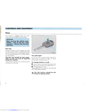 8
8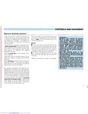 9
9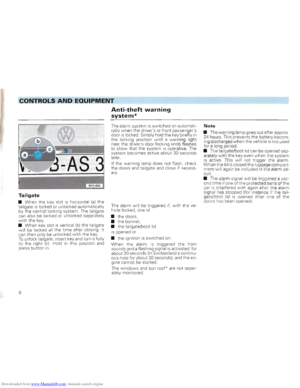 10
10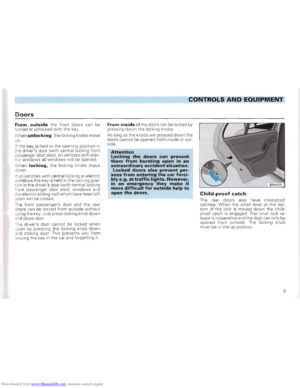 11
11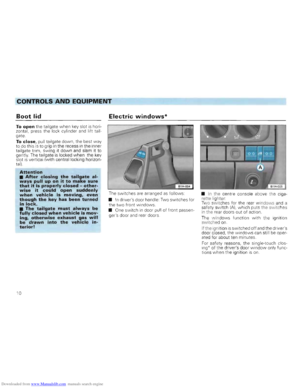 12
12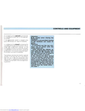 13
13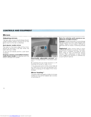 14
14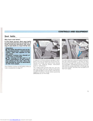 15
15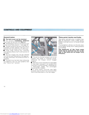 16
16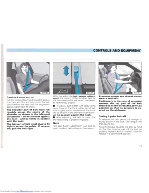 17
17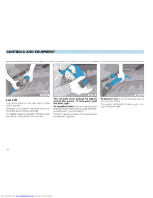 18
18 19
19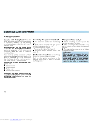 20
20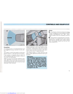 21
21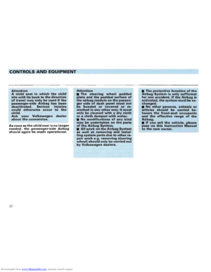 22
22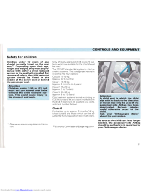 23
23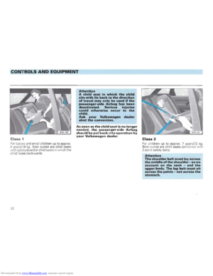 24
24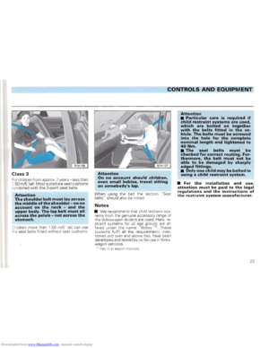 25
25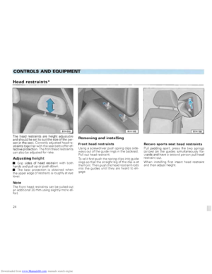 26
26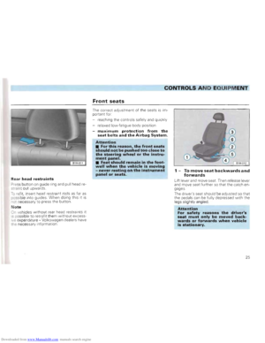 27
27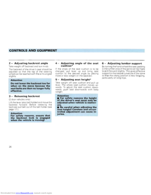 28
28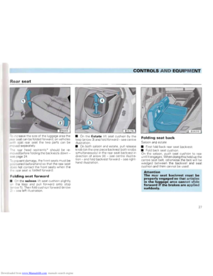 29
29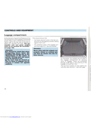 30
30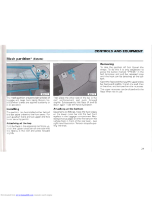 31
31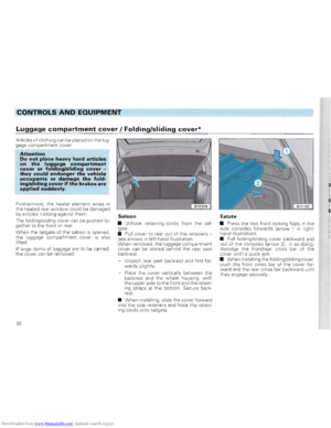 32
32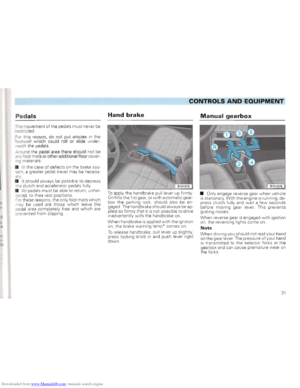 33
33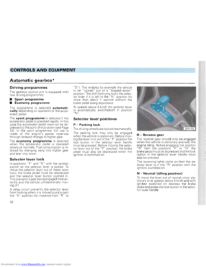 34
34 35
35 36
36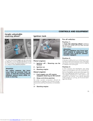 37
37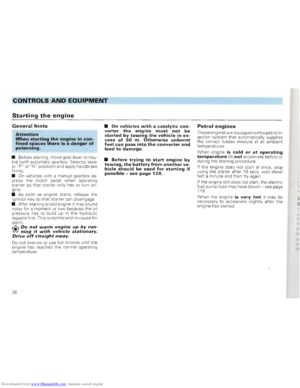 38
38 39
39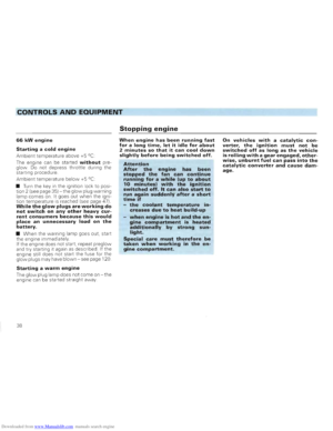 40
40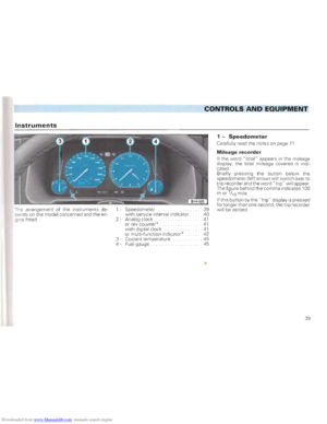 41
41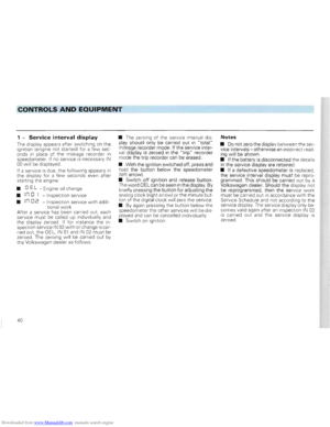 42
42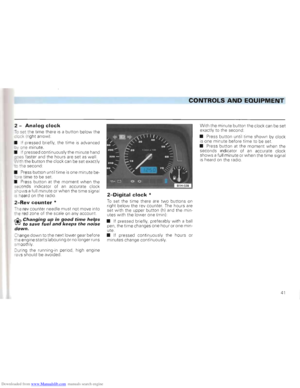 43
43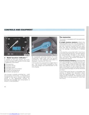 44
44 45
45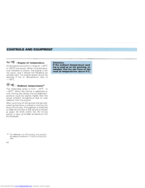 46
46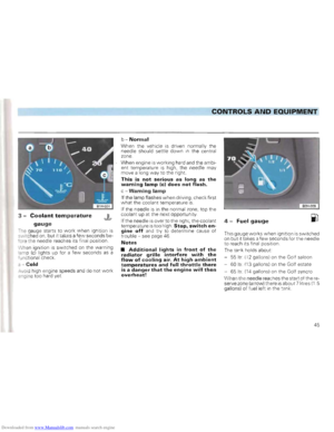 47
47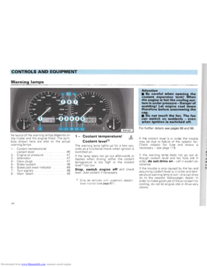 48
48 49
49 50
50 51
51 52
52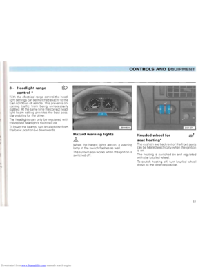 53
53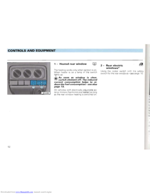 54
54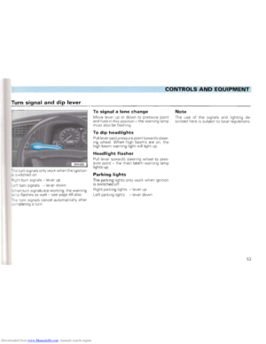 55
55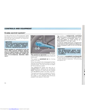 56
56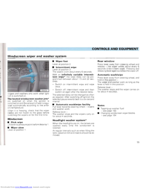 57
57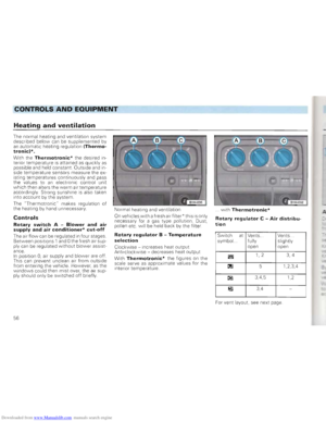 58
58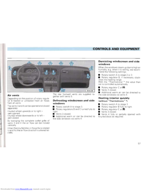 59
59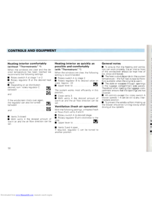 60
60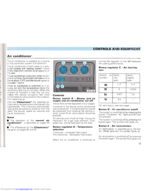 61
61 62
62 63
63 64
64 65
65 66
66 67
67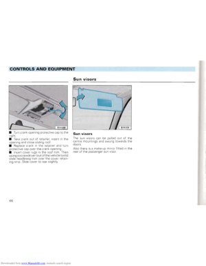 68
68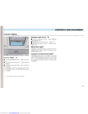 69
69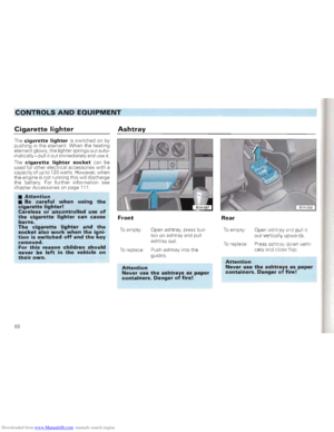 70
70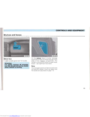 71
71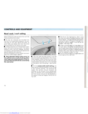 72
72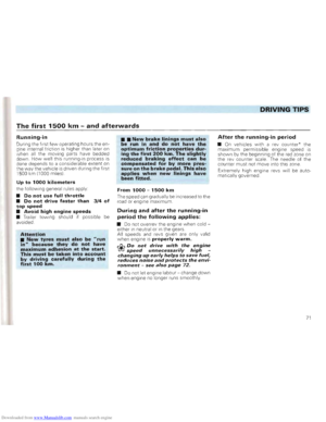 73
73 74
74 75
75 76
76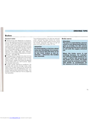 77
77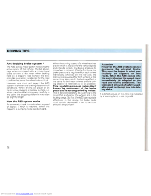 78
78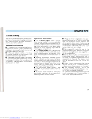 79
79 80
80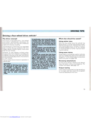 81
81 82
82 83
83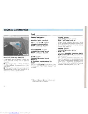 84
84 85
85 86
86 87
87 88
88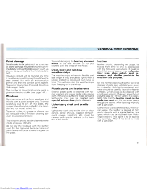 89
89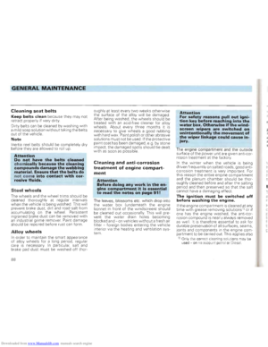 90
90 91
91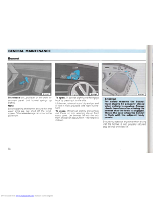 92
92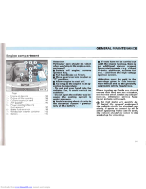 93
93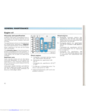 94
94 95
95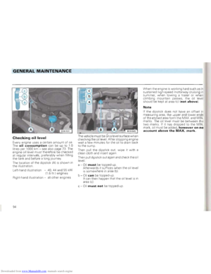 96
96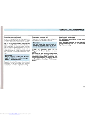 97
97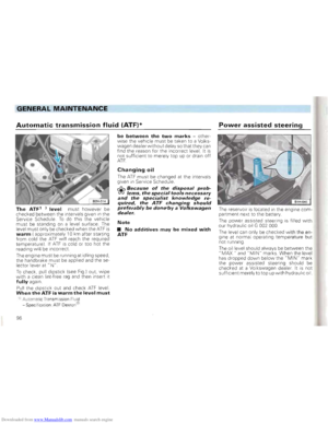 98
98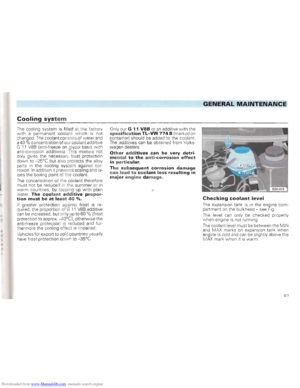 99
99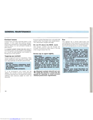 100
100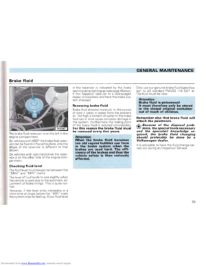 101
101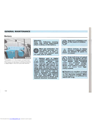 102
102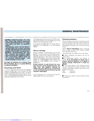 103
103 104
104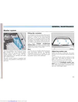 105
105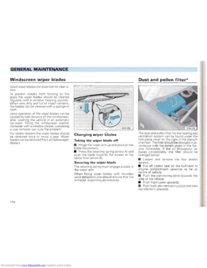 106
106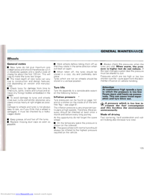 107
107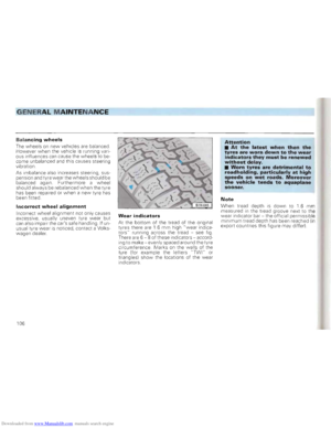 108
108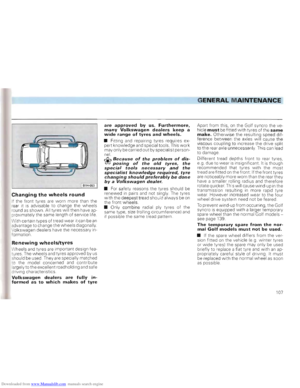 109
109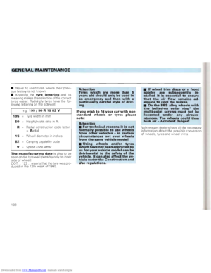 110
110 111
111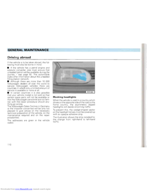 112
112 113
113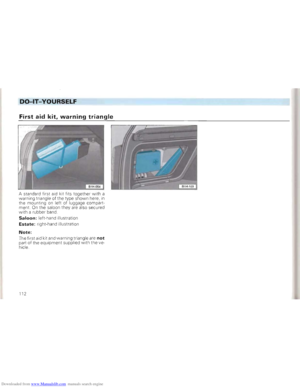 114
114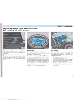 115
115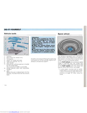 116
116 117
117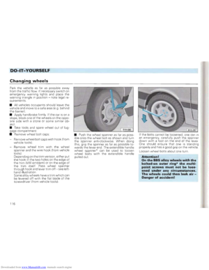 118
118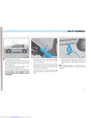 119
119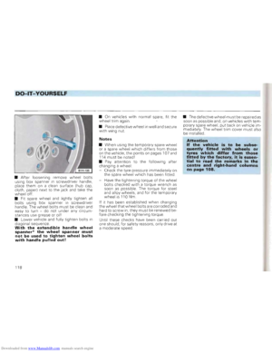 120
120 121
121 122
122 123
123 124
124 125
125 126
126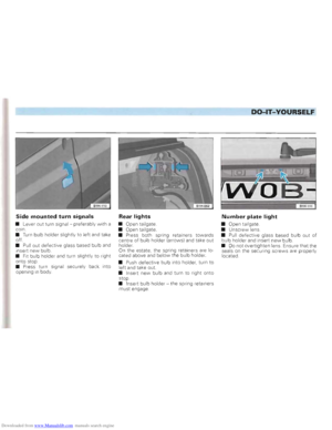 127
127 128
128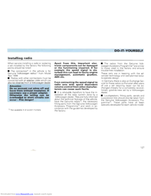 129
129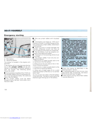 130
130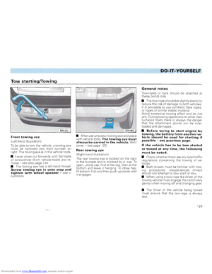 131
131 132
132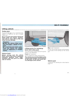 133
133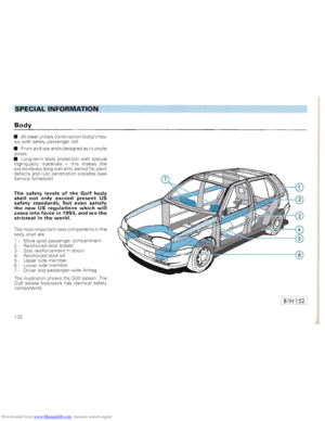 134
134 135
135 136
136 137
137 138
138 139
139 140
140 141
141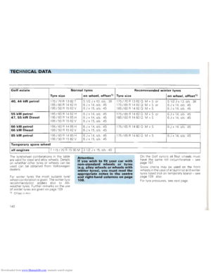 142
142 143
143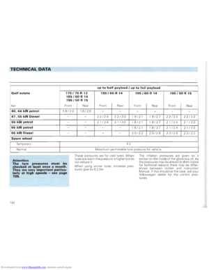 144
144 145
145 146
146 147
147 148
148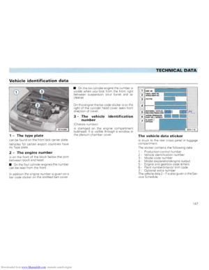 149
149 150
150 151
151 152
152 153
153 154
154 155
155