1993 VOLKSWAGEN CORRADO technical specifications
[x] Cancel search: technical specificationsPage 729 of 920
STARTER
Article Text (p. 3)
1993 Volkswagen Corrado
For Volkswagen Technical Site: http://vw.belcom.ru
Copyright © 1998 Mitchell Repair Information Company, LLC
Wednesday, March 22, 2000 09:23PM
STARTER NO-LOAD TEST
With starter on test bench, operate starter and check
ammeter, voltage, and RPM. Readings should be within specification.
See STARTER NO-LOAD TEST SPECIFICATIONS table.
STARTER NO-LOAD TEST SPECIFICATIONS TABLEÄÄÄÄÄÄÄÄÄÄÄÄÄÄÄÄÄÄÄÄÄÄÄÄÄÄÄÄÄÄÄÄÄÄÄÄÄÄÄÄÄÄVolts Amps RPM
11.5 ........... 65-95 .......... 6500
ÄÄÄÄÄÄÄÄÄÄÄÄÄÄÄÄÄÄÄÄÄÄÄÄÄÄÄÄÄÄÄÄÄÄÄÄÄÄÄÄÄÄ REMOVAL & INSTALLATION
CORRADO SLC & PASSAT
CAUTION: Failure to use Support Beam (VW 10-222A) and Leg Set (VW
10-222A/1) may result in misalignment of
engine/transmission assembly.
Removal & Installation
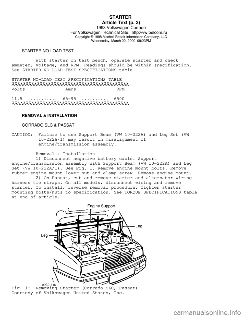
1) Disconnect negative battery cable. Support
engine/transmission assembly with Support Beam (VW 10-222A) and Leg
Set (VW 10-222A/1). See Fig. 1. Remove engine mount bolts. Remove
rubber engine mount lower nut and clamp screw. Remove engine mount.
2) On Passat, cut and remove starter and alternator wiring
harness tie straps. On all models, disconnect wiring and remove
starter. To install, reverse removal procedure. Tighten starter
mounting bolts/nuts to specification. See TORQUE SPECIFICATIONS table
at end of article.Fig. 1: Removing Starter (Corrado SLC, Passat)
Courtesy of Volkswagen United States, Inc.
Page 731 of 920

STARTER
Article Text (p. 5)
1993 Volkswagen Corrado
For Volkswagen Technical Site: http://vw.belcom.ru
Copyright © 1998 Mitchell Repair Information Company, LLC
Wednesday, March 22, 2000 09:23PM
STARTER SPECIFICATIONS
STARTER SPECIFICATIONS TABLEÄÄÄÄÄÄÄÄÄÄÄÄÄÄÄÄÄÄÄÄÄÄÄÄÄÄÄÄÄÄÄÄÄÄÄÄÄÄÄÄÄÄÄÄÄÄÄÄÄÄÄÄÄÄÄÄÄÄÄÄApplication Specification
Armature
Runout ................................... .002" (.05 mm)
End Play ................................. .002" (.05 mm)
Cold Cranking
Test Voltage ......................................... 12
Minimum Voltage ....................................... 9
Amps ................................................. 90
Minimum RPM ........................................ 1500
Solenoid Hold-In Winding Voltage ........ 4 Volts Minimum
Solenoid Pull-In Winding Voltage ................ 7 Volts
Commutator Runout ........................ .0004" (.01 mm)
Cranking Voltage ......................... 9 Volts Minimum
Starter Current Draw .................... 170 Amps Maximum
ÄÄÄÄÄÄÄÄÄÄÄÄÄÄÄÄÄÄÄÄÄÄÄÄÄÄÄÄÄÄÄÄÄÄÄÄÄÄÄÄÄÄÄÄÄÄÄÄÄÄÄÄÄÄÄÄÄÄÄÄ TORQUE SPECIFICATIONS
TORQUE SPECIFICATIONS TABLE
ÄÄÄÄÄÄÄÄÄÄÄÄÄÄÄÄÄÄÄÄÄÄÄÄÄÄÄÄÄÄÄÄÄÄÄÄÄÄÄÄÄÄÄÄÄÄÄÄÄÄÄÄÄÄÄÄÄÄÄÄApplication Ft. Lbs. (N.m)
Starter-To-Block Bolt/Nut
Corrado SLC, Passat ............................. 44 (60)
INCH Lbs. (N.m)
Solenoid Bolts ................................... 96 (11)
Through Bolts ..................................... 54 (6)
ÄÄÄÄÄÄÄÄÄÄÄÄÄÄÄÄÄÄÄÄÄÄÄÄÄÄÄÄÄÄÄÄÄÄÄÄÄÄÄÄÄÄÄÄÄÄÄÄÄÄÄÄÄÄÄÄÄÄÄÄEND OF ARTICLE
Page 735 of 920

STEERING COLUMN
Article Text (p. 4)
1993 Volkswagen Corrado
For Volkswagen Technical Site: http://vw.belcom.ru
Copyright © 1998 Mitchell Repair Information Company, LLC
Wednesday, March 22, 2000 09:23PM
notch with lower "U" joint slot. Install boot and damping grommet. Fit
steering box to frame while guiding pinion shaft into lower "U" joint.
2) Hand-tighten steering gear retaining nuts. Place wheels in
straight-ahead position. Align pinion shaft and "U" joint. Tighten
pinch bolt. Tighten steering gear retaining nuts. Connect gearshift
linkage. Check linkage for smooth operation.
TORQUE SPECIFICATIONS
TORQUE SPECIFICATIONS TABLEÄÄÄÄÄÄÄÄÄÄÄÄÄÄÄÄÄÄÄÄÄÄÄÄÄÄÄÄÄÄÄÄÄÄÄÄÄÄÄÄÄÄÄÄÄÄÄÄÄÄÄÄÄÄÄÄÄÄÄÄApplication Ft. Lbs. (N.m)
Pinch Bolt ....................................... 22 (30)
Steering Column-To-Instrument Panel
Retaining Bolt ................................. 15 (20)
Shear Bolt ........................................ (1)
Steering Gear Retaining Nut ...................... 22 (30)
Steering Wheel Nut ................................. 30 (40)
INCH Lbs. (N.m)
Air Bag Unit-To-Steering Wheel Screws .............. 89 (10)
(1) - Tighten until bolt head snaps off.
ÄÄÄÄÄÄÄÄÄÄÄÄÄÄÄÄÄÄÄÄÄÄÄÄÄÄÄÄÄÄÄÄÄÄÄÄÄÄÄÄÄÄÄÄÄÄÄÄÄÄÄÄÄÄÄÄÄÄÄÄEND OF ARTICLE
Page 740 of 920
STEERING COLUMN SWITCHES
Article Text (p. 5)
1993 Volkswagen Corrado
For Volkswagen Technical Site: http://vw.belcom.ru
Copyright © 1998 Mitchell Repair Information Company, LLC
Wednesday, March 22, 2000 09:23PM
1) Insert lock cylinder into steering lock housing. Insert
key into lock cylinder. Push lock cylinder fully into housing while
gently turning key.
2) Install combination switch and upper and lower steering
column covers. Install steering wheel and nut. Tighten steering wheel
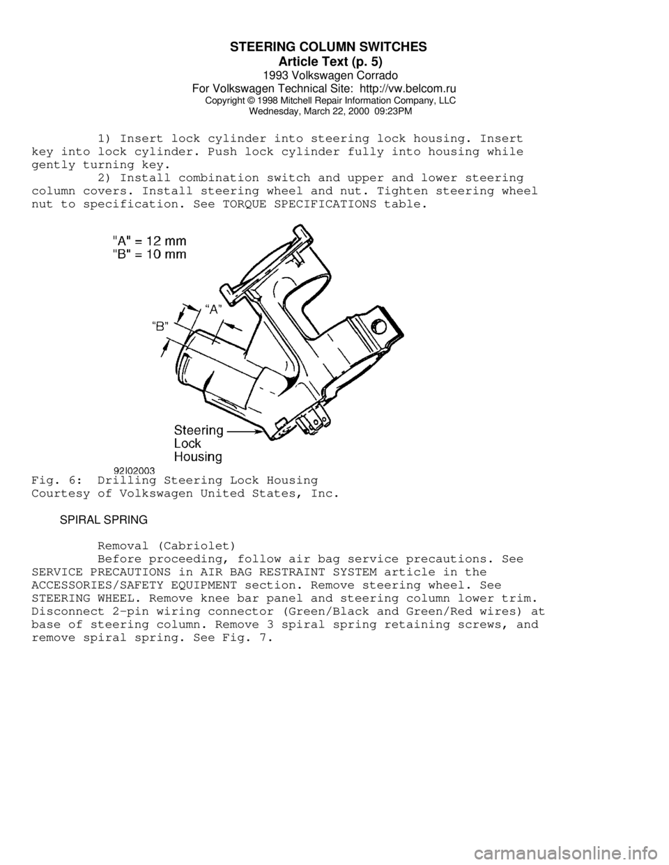
nut to specification. See TORQUE SPECIFICATIONS table.Fig. 6: Drilling Steering Lock Housing
Courtesy of Volkswagen United States, Inc.
SPIRAL SPRING
Removal (Cabriolet)
Before proceeding, follow air bag service precautions. See
SERVICE PRECAUTIONS in AIR BAG RESTRAINT SYSTEM article in the
ACCESSORIES/SAFETY EQUIPMENT section. Remove steering wheel. See
STEERING WHEEL. Remove knee bar panel and steering column lower trim.
Disconnect 2-pin wiring connector (Green/Black and Green/Red wires) at
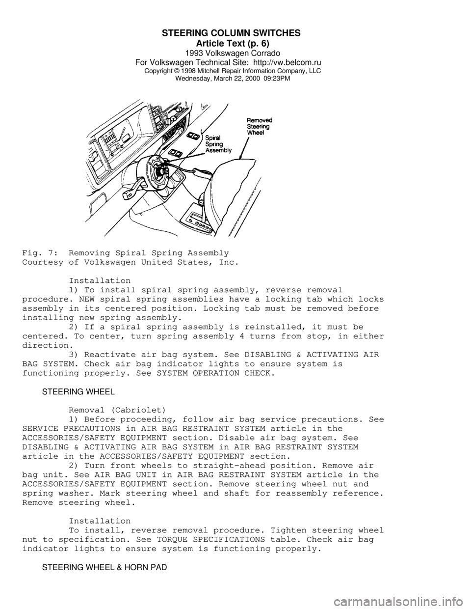
base of steering column. Remove 3 spiral spring retaining screws, and
remove spiral spring. See Fig. 7.
Page 741 of 920
STEERING COLUMN SWITCHES
Article Text (p. 6)
1993 Volkswagen Corrado
For Volkswagen Technical Site: http://vw.belcom.ru
Copyright © 1998 Mitchell Repair Information Company, LLC
Wednesday, March 22, 2000 09:23PMFig. 7: Removing Spiral Spring Assembly
Courtesy of Volkswagen United States, Inc.
Installation
1) To install spiral spring assembly, reverse removal
procedure. NEW spiral spring assemblies have a locking tab which locks
assembly in its centered position. Locking tab must be removed before
installing new spring assembly.
2) If a spiral spring assembly is reinstalled, it must be
centered. To center, turn spring assembly 4 turns from stop, in either
direction.
3) Reactivate air bag system. See DISABLING & ACTIVATING AIR
BAG SYSTEM. Check air bag indicator lights to ensure system is
functioning properly. See SYSTEM OPERATION CHECK.
STEERING WHEEL
Removal (Cabriolet)
1) Before proceeding, follow air bag service precautions. See
SERVICE PRECAUTIONS in AIR BAG RESTRAINT SYSTEM article in the
ACCESSORIES/SAFETY EQUIPMENT section. Disable air bag system. See
DISABLING & ACTIVATING AIR BAG SYSTEM in AIR BAG RESTRAINT SYSTEM
article in the ACCESSORIES/SAFETY EQUIPMENT section.
2) Turn front wheels to straight-ahead position. Remove air
bag unit. See AIR BAG UNIT in AIR BAG RESTRAINT SYSTEM article in the
ACCESSORIES/SAFETY EQUIPMENT section. Remove steering wheel nut and
spring washer. Mark steering wheel and shaft for reassembly reference.
Remove steering wheel.
Installation
To install, reverse removal procedure. Tighten steering wheel
nut to specification. See TORQUE SPECIFICATIONS table. Check air bag
indicator lights to ensure system is functioning properly.
STEERING WHEEL & HORN PAD
Page 742 of 920
STEERING COLUMN SWITCHES
Article Text (p. 7)
1993 Volkswagen Corrado
For Volkswagen Technical Site: http://vw.belcom.ru
Copyright © 1998 Mitchell Repair Information Company, LLC
Wednesday, March 22, 2000 09:23PM
Removal (Except Cabriolet)
1) Disconnect negative battery cable. Remove screws attaching
horn button assembly/center pad to steering wheel from behind steering
wheel (if equipped).
2) Pull horn button assembly/center pad from steering wheel.
Use a cloth covered screwdriver to pry off horn button assembly/center
pad (if necessary). Disassemble horn button assembly (if necessary).
3) Place springs, contacts, horn or cruise control harness
connectors and screws in order for reassembly reference. Place wheels
in straight-ahead position.
4) Remove steering wheel retaining nut and washer. Mark
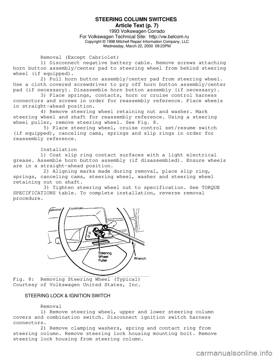
steering wheel and shaft for reassembly reference. Using a steering
wheel puller, remove steering wheel. See Fig. 8.
5) Place steering wheel, cruise control set/resume switch
(if equipped), canceling cams, springs and slip rings in order for
reassembly reference.
Installation
1) Coat slip ring contact surfaces with a light electrical
grease. Assemble horn button assembly (if disassembled). Ensure wheels
are in a straight-ahead position.
2) Aligning marks made during removal, place slip ring,
springs, canceling cams, steering wheel, washer and steering wheel
retaining nut on shaft.
3) Tighten steering wheel nut to specification. See TORQUE
SPECIFICATIONS table. To complete installation, reverse removal
procedure.Fig. 8: Removing Steering Wheel (Typical)
Courtesy of Volkswagen United States, Inc.
STEERING LOCK & IGNITION SWITCH
Removal
1) Remove steering wheel, upper and lower steering column
covers and combination switch. Disconnect ignition switch harness
connectors.
2) Remove clamping washers, spring and contact ring from
steering column. Remove steering lock housing mounting bolt. Remove
steering lock housing from steering column.
Page 743 of 920

STEERING COLUMN SWITCHES
Article Text (p. 8)
1993 Volkswagen Corrado
For Volkswagen Technical Site: http://vw.belcom.ru
Copyright © 1998 Mitchell Repair Information Company, LLC
Wednesday, March 22, 2000 09:23PM
Installation
1) To install, reverse removal procedure. Slide steering lock
housing onto steering column. Install contact ring, spring and
clamping washers onto steering column. Ensure proper operation of
steering lock and ignition switch.
NOTE: On Corrado SLC, pull steering column upward from steering
column tube as far as possible to ensure proper column
position.
2) Install combination switch, upper and lower steering
column covers and steering wheel. Tighten steering wheel nut to
specification. See TORQUE SPECIFICATIONS table.
TORQUE SPECIFICATIONS
TORQUE SPECIFICATIONS TABLEÄÄÄÄÄÄÄÄÄÄÄÄÄÄÄÄÄÄÄÄÄÄÄÄÄÄÄÄÄÄÄÄÄÄÄÄÄÄÄÄÄÄÄÄÄÄÄÄÄÄÄÄÄÄÄÄÄÄÄÄApplication Ft. Lbs. (N.m)
Steering Wheel Nut ................................. 30 (40)
INCH Lbs. (N.m)
Air Bag Unit-To-Steering Wheel Screws .............. 89 (10)
ÄÄÄÄÄÄÄÄÄÄÄÄÄÄÄÄÄÄÄÄÄÄÄÄÄÄÄÄÄÄÄÄÄÄÄÄÄÄÄÄÄÄÄÄÄÄÄÄÄÄÄÄÄÄÄÄÄÄÄÄEND OF ARTICLE
Page 746 of 920
STEERING GEAR - POWER RACK & PINION
Article Text (p. 3)
1993 Volkswagen Corrado
For Volkswagen Technical Site: http://vw.belcom.ru
Copyright © 1998 Mitchell Repair Information Company, LLC
Wednesday, March 22, 2000 09:23PM
Remove rack and pinion assembly. See POWER RACK & PINION
under REMOVAL & INSTALLATION. Loosen lock nut. Turn adjuster bolt
until pinion shaft can be turned by hand without binding. Hold
adjuster bolt in position while tightening lock nut.
REMOVAL & INSTALLATION
POWER STEERING PUMP
Removal
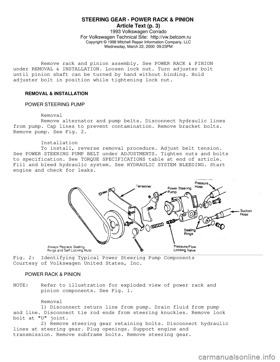
Remove alternator and pump belts. Disconnect hydraulic lines
from pump. Cap lines to prevent contamination. Remove bracket bolts.
Remove pump. See Fig. 2.
Installation
To install, reverse removal procedure. Adjust belt tension.
See POWER STEERING PUMP BELT under ADJUSTMENTS. Tighten nuts and bolts
to specification. See TORQUE SPECIFICATIONS table at end of article.
Fill and bleed hydraulic system. See HYDRAULIC SYSTEM BLEEDING. Start
engine and check for leaks.Fig. 2: Identifying Typical Power Steering Pump Components
Courtesy of Volkswagen United States, Inc.
POWER RACK & PINION
NOTE: Refer to illustration for exploded view of power rack and
pinion components. See Fig. 1.
Removal
1) Disconnect return line from pump. Drain fluid from pump
and line. Disconnect tie rod ends from steering knuckles. Remove lock
bolt at "U" joint.
2) Remove steering gear retaining bolts. Disconnect hydraulic
lines at steering gear. Plug openings. Support engine and
transmission. Remove subframe bolts. Remove steering gear.