1993 VOLKSWAGEN CORRADO instrument cluster
[x] Cancel search: instrument clusterPage 376 of 920

A/C-HEATER SYSTEM - MANUAL
Article Text
1993 Volkswagen Corrado
For Volkswagen Technical Site: http://vw.belcom.ru
Copyright © 1998 Mitchell Repair Information Company, LLC
Wednesday, March 22, 2000 08:49PM
ARTICLE BEGINNING
1993 MANUAL A/C-HEATER SYSTEMS
Volkswagen United States, Inc.
Corrado SLC
SPECIFICATIONS
SPECIFICATIONS TABLEÄÄÄÄÄÄÄÄÄÄÄÄÄÄÄÄÄÄÄÄÄÄÄÄÄÄÄÄÄÄÄÄÄÄÄÄÄÄÄÄÄÄÄÄÄÄÄÄÄÄÄÄÄÄÄÄÄÄÄÄÄÄÄApplication Specification
Compressor Type ........................ Sanden SD-709 7-Cyl.
Compressor Belt Tension (1)
System Oil Capacity (2) ........................ 3.9-4.4 ozs.
Refrigerant (R-134a) Capacity ................ 35.0-36.6 ozs.
System Operating Pressures
High Side ............................ 203 psi (13.8 kg/cm
ý)
Low Side ............................... 17 psi (1.1 kg/cm
ý)
(1) - Ribbed belt uses automatic belt tensioner.
(2) - Use PAG Compressor Oil (Part No. G 052 154 A2).
ÄÄÄÄÄÄÄÄÄÄÄÄÄÄÄÄÄÄÄÄÄÄÄÄÄÄÄÄÄÄÄÄÄÄÄÄÄÄÄÄÄÄÄÄÄÄÄÄÄÄÄÄÄÄÄÄÄÄÄÄÄÄÄWARNING: To avoid injury from accidental air bag deployment, read and
carefully follow all SERVICE PRECAUTIONS and DISABLING &
ACTIVATING AIR BAG SYSTEM procedures.
AIR BAG SYSTEM PRECAUTIONS
SYSTEM OPERATION CHECK
Two lights pertaining to air bag system are located directly
above air bag symbol in instrument cluster. Control light is used to
indicate readiness of system. With ignition on, control light comes on
for about 5-8 seconds then goes out, while diagnosis unit in air bag
control unit performs an electronic test cycle of system.
If control light does not function as described, a fault
probably exists in system. If fault occurs while ignition is on, it
will be stored in fault memory. Warning light will then come on, and
air bag system will be switched off. If warning light comes on or
flickers while driving, air bag system should be tested.
SERVICE PRECAUTIONS
Observe these precautions when working with air bag systems:
* DO NOT use computer memory saver tool. Using computer memory
tool will keep air bag system active and may cause accidental
deployment of air bag unit.
Page 385 of 920

A/C-HEATER SYSTEM - MANUAL
Article Text (p. 10)
1993 Volkswagen Corrado
For Volkswagen Technical Site: http://vw.belcom.ru
Copyright © 1998 Mitchell Repair Information Company, LLC
Wednesday, March 22, 2000 08:49PM
INSTRUMENT PANEL
Removal & Installation
1) Disable air bag system. See AIR BAG SYSTEM SAFETY article
in GENERAL SERVICING. Disconnect battery. Remove storage trays and
panel under left side of instrument panel. Remove steering wheel.
Remove trim panel around instrument cluster.
2) Remove center console. Remove dash vents at each side,
glove box and radio. Remove center storage box, A/C-heater control
panel trim, and A/C-heater control panel screws. Push A/C-heater
control panel away from instrument panel.
3) Remove screws at both sides of instrument panel, at center
support, and 2 screws next to windshield. Detach instrument panel and
pull part way out.
4) Disconnect wiring harnesses from instrument panel.
Disconnect speedometer cable, if present. Remove instrument panel. To
install, reverse removal procedure.
THERMOSTAT
Removal & Installation
1) Remove thermostat cover. See Fig. 3. Remove thermostat
mounting screw and disconnect harness connector. Remove thermostat by
pulling sensing (capillary) tube through grommet.
2) To install, reverse removal procedures. Measure back 13"
(330 mm) from end of sensing tube and tape spot. Insert sensing tube
into evaporator guide channel up to tape.
TORQUE SPECIFICATIONS
TORQUE SPECIFICATIONS TABLEÄÄÄÄÄÄÄÄÄÄÄÄÄÄÄÄÄÄÄÄÄÄÄÄÄÄÄÄÄÄÄÄÄÄÄÄÄÄÄÄÄÄÄÄÄÄÄÄÄÄÄÄÄÄApplication Ft. Lbs. (N.m)
A/C Compressor Bolt/Nut .................... 33 (45)
A/C Compressor Bracket Bolt/Nut ............ 25 (35)
A/C Compressor Hoses
Discharge ................................. 18 (25)
Suction ................................... 25 (35)
ÄÄÄÄÄÄÄÄÄÄÄÄÄÄÄÄÄÄÄÄÄÄÄÄÄÄÄÄÄÄÄÄÄÄÄÄÄÄÄÄÄÄÄÄÄÄÄÄÄÄÄÄÄÄ WIRING DIAGRAMS
Page 398 of 920

ABBREVIATIONS
Article Text (p. 6)
1993 Volkswagen Corrado
For Volkswagen Technical Site: http://vw.belcom.ru
Copyright © 1998 Mitchell Repair Information Company, LLC
Wednesday, March 22, 2000 08:49PM
"H" ABBREVIATION TABLEÚÄÄÄÄÄÄÄÄÄÄÄÄÄÄÄÄÄÂÄÄÄÄÄÄÄÄÄÄÄÄÄÄÄÄÄÄÄÄÄÄÄÄÄÄÄÄÄÄÄÄÄÄÄÄÄÄÄÄÄÄÄÄÄÄÄÄÄÄ¿
³ABBREVIATION
³DEFINITION ³
ÃÄÄÄÄÄÄÄÄÄÄÄÄÄÄÄÄÄÅÄÄÄÄÄÄÄÄÄÄÄÄÄÄÄÄÄÄÄÄÄÄÄÄÄÄÄÄÄÄÄÄÄÄÄÄÄÄÄÄÄÄÄÄÄÄÄÄÄÄ´
³H/D
³Heavy Duty ³
³HAC
³High Altitude Compensation ³
³HC
³Hydrocarbons ³
³HEDF
³High Speed Electro Drive Fan relay or circuit ³
³HEGO
³Heated Exhaust Gas Oxygen Sensor ³
³HEGOG
³HEGO Ground circuit ³
³HEI
³High Energy Ignition ³
³HLDT
³Headlight ³
³HO
³High Output ³
³HP
³High Performance ³
³HSC
³High Swirl Combustion ³
³HSO
³High Specific Output ³
³HTR
³Heater ³
³HVAC
³Heating ³
³Headlt.
³Headlight ³
³Hg
³Mercury ³
³Hgt.
³Height ³
³Htr.
³Heater ³
³Hz
³Hertz (Cycles Per Second) ³
ÀÄÄÄÄÄÄÄÄÄÄÄÄÄÄÄÄÄÁÄÄÄÄÄÄÄÄÄÄÄÄÄÄÄÄÄÄÄÄÄÄÄÄÄÄÄÄÄÄÄÄÄÄÄÄÄÄÄÄÄÄÄÄÄÄÄÄÄÄÙ "I" ABBREVIATION TABLE
"I" ABBREVIATION TABLE
ÚÄÄÄÄÄÄÄÄÄÄÄÄÄÄÄÄÄÂÄÄÄÄÄÄÄÄÄÄÄÄÄÄÄÄÄÄÄÄÄÄÄÄÄÄÄÄÄÄÄÄÄÄÄÄÄÄÄÄÄÄÄÄÄÄÄÄÄÄ¿
³ABBREVIATION
³DEFINITION ³
ÃÄÄÄÄÄÄÄÄÄÄÄÄÄÄÄÄÄÅÄÄÄÄÄÄÄÄÄÄÄÄÄÄÄÄÄÄÄÄÄÄÄÄÄÄÄÄÄÄÄÄÄÄÄÄÄÄÄÄÄÄÄÄÄÄÄÄÄÄ´
³I.D.
³Inside Diameter ³
³IAC
³Idle Air Control ³
³IACV
³Idle Air Control Valve ³
³IC
³Integrated Circuit ³
³ID
³Identification ³
³IDM
³Ignition Diagnostic Monitor ³
³IGN
³Ignition system or circuit ³
³ILC
³Idle Load Compensator ³
³In. Hg
³Inches of Mercury ³
³INCH Lbs.
³Inch Pounds ³
³INFL REST
³Inflatable Restraint ³
³INJ
³Injector or Injection ³
³IP
³Instrument Panel ³
³IPC
³Instrument Panel Cluster ³
³ISA
³Idle Speed Actuator ³
³ISC
³Idle Speed Control ³
³ISS
³Idle Stop Solenoid ³
³ITS
³Idle Tracking Switch ³
³IVSV
³Idle Vacuum Switching Valve ³
³Ign.
³Ignition ³
³In.
³Inches ³
Page 493 of 920

ELECTRICAL COMPONENT LOCATOR
Article Text (p. 35)
1993 Volkswagen Corrado
For Volkswagen Technical Site: http://vw.belcom.ru
Copyright © 1998 Mitchell Repair Information Company, LLC
Wednesday, March 22, 2000 09:09PM
plate.
Instrument Cluster Voltage Stabilizer On back of instrument cluster,
above fuel gauge.ÄÄÄÄÄÄÄÄÄÄÄÄÄÄÄÄÄÄÄÄÄÄÄÄÄÄÄÄÄÄÄÄÄÄÄÄÄÄÄÄÄÄÄÄÄÄÄÄÄÄÄÄÄÄÄÄÄÄÄÄÄÄÄÄÄÄÄÄÄÄEND OF ARTICLE
Page 610 of 920

HOW TO USE SYSTEM WIRING DIAGRAMS
Article Text (p. 7)
1993 Volkswagen Corrado
For Volkswagen Technical Site: http://vw.belcom.ru
Copyright © 1998 Mitchell Repair Information Company, LLC
Wednesday, March 22, 2000 09:11PM
Instrument Cluster ........................ Analog Instrument Panels
Intake Air Temperature (IAT) Sensor ............. Engine Performance
Interior Lights ....................... Illumination/Interior Lights
Interlock Switch .......................................... Starters
Junction Block .................................. Power Distribution
Keyless Entry Receiver ........................ Remote Keyless Entry
Key Reminder Switch ....................................... Starters
Knock Sensor .................................... Engine Performance
Lamp Control Module ................................ Exterior Lights
License Plate Lamp ................................. Exterior Lights
Lighting Control Module ................... Lighting Control Modules
Anti-Theft System
Daytime Running Lights
Headlight Systems
Lower Relay .................................. Power Convertible Top
Malfunction Indicator Light (MIL) ............... Engine Performance
Instrument Panels
Manifold Absolute Pressure (MAP) Sensor ......... Engine Performance
Mass Airflow (MAF) Sensor ....................... Engine Performance
Mega Fuse .................................. Generators & Regulators
Memory Seat/Mirror Module ........................... Memory Systems
Mirror Defogger ............................... Rear Window Defogger
Moon Roof Motor .................................... Power Moon Roof
Moon Roof Relay .................................... Power Moon Roof
Multi-Function Control Module ...................... Warning Systems
Neutral Safety Switch ..................................... Starters
Oil Level Switch ................................ Engine Performance
Oil Pressure Switch/Sending Unit .......... Analog Instrument Panels
Engine Performance
Overhead Console .................................. Overhead Console
Oxygen Sensor(s) (O2S) .......................... Engine Performance
Parking Brake Switch ...................... Analog Instrument Panels
Park Lights ........................................ Exterior Lights
Park/Neutral Position Switch .............................. Starters
Engine Performance
Anti-Theft System
Body Control Module
Perimeter Lighting Control Relay ................... Exterior Lights
Power Amplifier ..................................... Power Antennas
Power Antenna Module ................................ Power Antennas
Power Antenna Motor ................................. Power Antennas
Power Distribution Center ....................... Power Distribution
Generators & Regulators
Starters
Power Door Lock Motors ............................ Power Door Locks
Power Mirror Motors .................................. Power Mirrors
Memory Systems
Power Sliding Door Controller .............. Power Sliding Side Door
Power Seat Motors ...................................... Power Seats
Memory Systems
Power Steering Pressure Switch .................. Engine Performance
Power Top Motor .............................. Power Convertible Top
Page 620 of 920

INSTRUMENT PANEL
Article Text
1993 Volkswagen Corrado
For Volkswagen Technical Site: http://vw.belcom.ru
Copyright © 1998 Mitchell Repair Information Company, LLC
Wednesday, March 22, 2000 09:12PM
ARTICLE BEGINNING
1993 ACCESSORIES & EQUIPMENT
Volkswagen Instrument Panel
Corrado SLC
DESCRIPTION & OPERATION
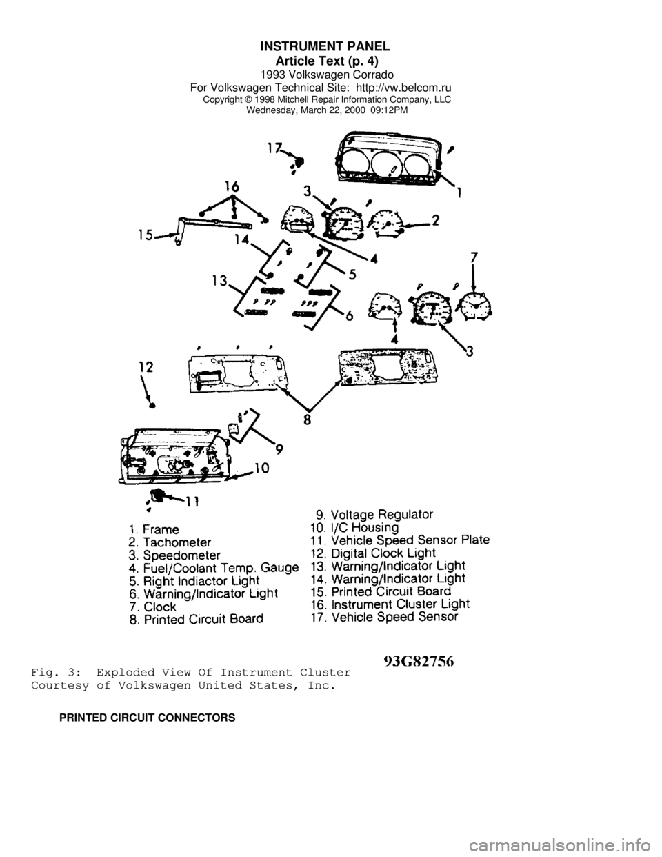
Instrument cluster for most models includes speedometer, fuel
gauge and temperature gauge. Optional instruments include clock,
tachometer, voltmeter and oil temperature gauge. See Figs. 3.
Printed circuit provides voltage to gauges. A voltage
regulator attached to printed circuit controls voltage to fuel and
temperature gauges. Most warning lights are a Light Emitting Diode
(LED). To replace diode, pull from printed circuit socket.
TESTING
VOLTAGE REGULATOR TEST
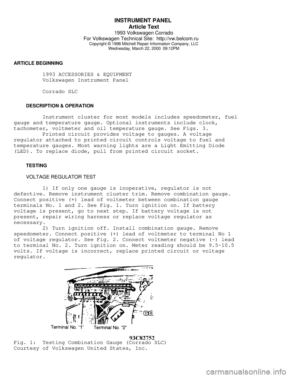
1) If only one gauge is inoperative, regulator is not
defective. Remove instrument cluster trim. Remove combination gauge.
Connect positive (+) lead of voltmeter between combination gauge
terminals No. 1 and 2. See Fig. 1. Turn ignition on. If battery
voltage is present, go to next step. If battery voltage is not
present, repair wiring harness or replace voltage regulator as
necessary.
2) Turn ignition off. Install combination gauge. Remove
speedometer. Connect positive (+) lead of voltmeter to terminal No 1
of voltage regulator. See Fig. 2. Connect voltmeter negative (-) lead
to terminal No. 2. Turn ignition on. Meter reading should be 9.5-10.5
volts. If voltage is incorrect, replace printed circuit or voltage
regulator.Fig. 1: Testing Combination Gauge (Corrado SLC)
Courtesy of Volkswagen United States, Inc.
Page 622 of 920

INSTRUMENT PANEL
Article Text (p. 3)
1993 Volkswagen Corrado
For Volkswagen Technical Site: http://vw.belcom.ru
Copyright © 1998 Mitchell Repair Information Company, LLC
Wednesday, March 22, 2000 09:12PM
Corrado SLC ................... 80 ........................ Normal
50 ....................... (2) Hot
(1) - Information for EuroVan not available from manufacturer.
(2) - With Red LED flashing.ÄÄÄÄÄÄÄÄÄÄÄÄÄÄÄÄÄÄÄÄÄÄÄÄÄÄÄÄÄÄÄÄÄÄÄÄÄÄÄÄÄÄÄÄÄÄÄÄÄÄÄÄÄÄÄÄÄÄÄÄÄÄÄÄÄÄÄÄÄÄ REMOVAL & INSTALLATION
CAUTION: DO NOT damage printed circuit when installing instruments.
INSTRUMENT CLUSTER
Removal & Installation
1) Obtain radio code. Disconnect negative battery cable.
Remove steering wheel only when removing complete instrument cluster
housing. Remove trim screw caps and screws located on lower part of
instrument cluster trim. Remove instrument cluster trim.
2) Remove trip odometer reset button. Remove trim cover
retaining screws. Remove trim cover from instrument cluster. Remove
instrument cluster housing retaining screws. Pull instrument cluster
from dash panel. Disconnect multi-point connector, MFI vacuum hose (if
equipped) and speedometer drive cable. Remove instrument cluster
housing.
NOTE: All components in instrument cluster, except for printed
circuit, can be removed from front, without removing
complete instrument cluster housing.
3) Disconnect speedometer cable, remove mounting screws and
pull speedometer from housing. Squeeze locating pins on other
instruments and pull from housing. To install, reverse removal
procedure.
Page 623 of 920

INSTRUMENT PANEL
Article Text (p. 4)
1993 Volkswagen Corrado
For Volkswagen Technical Site: http://vw.belcom.ru
Copyright © 1998 Mitchell Repair Information Company, LLC
Wednesday, March 22, 2000 09:12PMFig. 3: Exploded View Of Instrument Cluster
Courtesy of Volkswagen United States, Inc.
PRINTED CIRCUIT CONNECTORS