1993 VOLKSWAGEN CORRADO wheel bolts
[x] Cancel search: wheel boltsPage 427 of 920

AXLE SHAFTS
Article Text
1993 Volkswagen Corrado
For Volkswagen Technical Site: http://vw.belcom.ru
Copyright © 1998 Mitchell Repair Information Company, LLC
Wednesday, March 22, 2000 08:57PM
ARTICLE BEGINNING
1993-94 DRIVE AXLES
Volkswagen Axle Shafts - FWD
Corrado SLC, Passat
TROUBLE SHOOTING
Refer to TROUBLE SHOOTING - BASIC PROCEDURES article in the
GENERAL TROUBLE SHOOTING section.
REMOVAL, DISASSEMBLY, REASSEMBLY & INSTALLATION
NOTE: Clean bolts and nuts to ensure tightening torque is correct.
AXLE SHAFT
Removal
1) Remove axle shaft nut. Remove wheel. Remove brake caliper,
and secure aside. Remove tie rod end bolts.
2) Remove 2 bolts attaching spindle assembly to strut
assembly. Remove lower ball joint bolt or nut if necessary. Remove
spindle assembly. Loosen inner CV joint from transaxle flange. On
models with V6 engine, use Axle Press (3283) to press axle from wheel
housing. Clean old locking compound from splines. Remove axle shaft
assembly. See Fig. 1.
Disassembly & Reassembly
1) Remove axle shaft boot(s). Using a drift, remove
protective cap from CV joint. Remove circlip from inner CV joint.
Support CV joint with axle assembly on Support Stand (VW 402).
2) Using Driver (VW 408A), press inner CV joint off axle
shaft. DO NOT disassemble inner CV joint, replace complete unit. To
remove outer CV joint, use a driver and hammer to drive CV joint off
axle shaft.
3) Rotate inner race and remove balls. Inspect for galling or
wear. Cover balls with grease and reinstall in race.
4) To reassemble, reverse disassembly procedure. Refer to the
AXLE SHAFT LENGTH table. Use new circlips and boot clamps during
assembly.
Installation
To install, reverse removal procedure. Install new axle shaft
nut. On models with V6 engine, apply locking compound to splines. See
the TORQUE SPECIFICATIONS table.
Page 437 of 920

BRAKE SYSTEM
Article Text (p. 6)
1993 Volkswagen Corrado
For Volkswagen Technical Site: http://vw.belcom.ru
Copyright © 1998 Mitchell Repair Information Company, LLC
Wednesday, March 22, 2000 08:57PM
guide pin using an open end wrench. Remove lower caliper mounting
bolt. Push caliper assembly upward and swing out from bottom.
2) Siphon small amount of brake fluid from reservoir. Remove
pads and retaining springs from caliper support. Replace pads
exceeding wear limit. Wear limit of pads is .28" (7.0 mm), including
backing plate. See Fig. 4 or 5.
Installation
1) Seat caliper piston fully into cylinder bore. Install
inner pad and then outer pad. Swing caliper assembly down. Hold lower
guide pin using an open end wrench.
2) Install lower caliper mounting bolt. Depress brake pedal
several times to allow pads to move into operating position. Ensure
master cylinder reservoir fluid level is full.
FRONT & REAR BRAKE CALIPER
Removal & Installation
1) Raise and support vehicle. Remove wheels. Disconnect
brakeline from caliper, and plug openings. Bend back locking tabs (if
equipped) on mounting bolts. If removing rear brake calipers,
disconnect parking brake cables.
2) On all calipers, remove caliper mounting bolts. See Fig. 4
or 6. Remove caliper assembly from wheel bearing housing. To install,
reverse removal procedure. Use NEW lock plates (if equipped) and
mounting bolts. Bleed hydraulic brake system. See BLEEDING PROCEDURES
under BLEEDING BRAKE SYSTEM.
FRONT & REAR BRAKE ROTOR
Removal
Raise and support vehicle. Remove wheels. Remove caliper and
suspend from frame with wire. Remove countersunk screw that holds
rotor to hub. Pull rotor off hub.
Installation
To install, reverse removal procedure. Adjust wheel bearings
(if necessary). See WHEEL BEARINGS under ADJUSTMENTS.
REAR DISC BRAKE PADS
Removal
Raise and support vehicle. Remove rear wheels. Disconnect
parking brake cable from caliper. Remove caliper mounting bolts.
Remove caliper and wire aside. Siphon small amount of brake fluid from
reservoir. Remove pads and retaining springs from caliper support.
Replace pads that exceed wear limit. Wear limit of pads is .28" (7.0
mm), including backing plate.
Installation
Seat caliper piston fully into cylinder bore. Install inner
pad first and then install outer pad. Position caliper. Install
Page 440 of 920

BRAKE SYSTEM
Article Text (p. 9)
1993 Volkswagen Corrado
For Volkswagen Technical Site: http://vw.belcom.ru
Copyright © 1998 Mitchell Repair Information Company, LLC
Wednesday, March 22, 2000 08:57PM
TORQUE SPECIFICATIONS
TORQUE SPECIFICATIONS TABLEÄÄÄÄÄÄÄÄÄÄÄÄÄÄÄÄÄÄÄÄÄÄÄÄÄÄÄÄÄÄÄÄÄÄÄÄÄÄÄÄÄÄÄÄÄÄÄÄÄÄÄÄÄÄÄÄÄÄÄÄApplication Ft. Lbs. (N.m)
Caliper Mounting Bolts (1) ........................ 26 (35)
Pad Carrier Mounting Bolt
Front .......................................... 92 (125)
Rear ............................................ 48 (65)
Rear Backing Plate-To-Flange Bolt ................ 44 (60)
Wheel Lug Nut .................................... 81 (110)
INCH Lbs. (N.m)
Wheel Cylinder Bolt ............................... 80 (9)
(1) - Always replace all self-locking bolts.
ÄÄÄÄÄÄÄÄÄÄÄÄÄÄÄÄÄÄÄÄÄÄÄÄÄÄÄÄÄÄÄÄÄÄÄÄÄÄÄÄÄÄÄÄÄÄÄÄÄÄÄÄÄÄÄÄÄÄÄÄ DISC BRAKE SPECIFICATIONS
DISC BRAKE SPECIFICATIONS TABLE (1)
ÄÄÄÄÄÄÄÄÄÄÄÄÄÄÄÄÄÄÄÄÄÄÄÄÄÄÄÄÄÄÄÄÄÄÄÄÄÄÄÄÄÄÄÄÄÄÄÄÄÄÄÄÄÄÄÄÄÄÄÄApplication In. (mm)
Front
Disc Diameter .............................. 11.02 (280)
Original Thickness ........................... .866 (22)
Wear Limit ................................... .787 (20)
Rear
Original Thickness ........................... .394 (10)
Wear Limit .................................... .315 (8)
(1) - Lateral runout is .002" (.05 mm).
ÄÄÄÄÄÄÄÄÄÄÄÄÄÄÄÄÄÄÄÄÄÄÄÄÄÄÄÄÄÄÄÄÄÄÄÄÄÄÄÄÄÄÄÄÄÄÄÄÄÄÄÄÄÄÄÄÄÄÄÄEND OF ARTICLE
Page 448 of 920

CLUTCH
Article Text (p. 3)
1993 Volkswagen Corrado
For Volkswagen Technical Site: http://vw.belcom.ru
Copyright © 1998 Mitchell Repair Information Company, LLC
Wednesday, March 22, 2000 08:58PM
front transmission mount. Attach Engine Support (10-222A) with Bases
(10-222A/1) to engine. Slightly tighten engine support and remove
starter. Remove left transaxle mount bracket.
5) Remove long left side transmission support bracket. Remove
balance weight from mount. Remove heat shield for right side inner CV
(constant velocity) joint.
6) Disconnect axle shafts at flanges and wire aside. Remove
left side transaxle mount from transaxle. It will be necessary to push
rearward on mount for clearance to remove long transaxle mount bolt.
7) Push transaxle mount to right and pull down to remove from
vehicle. Remove small gear carrier housing cover. Support transaxle
with floor jack. Remove rear transaxle mount. Remove lower transaxle-
to-engine bolts. Carefully pry transaxle from engine and lower.
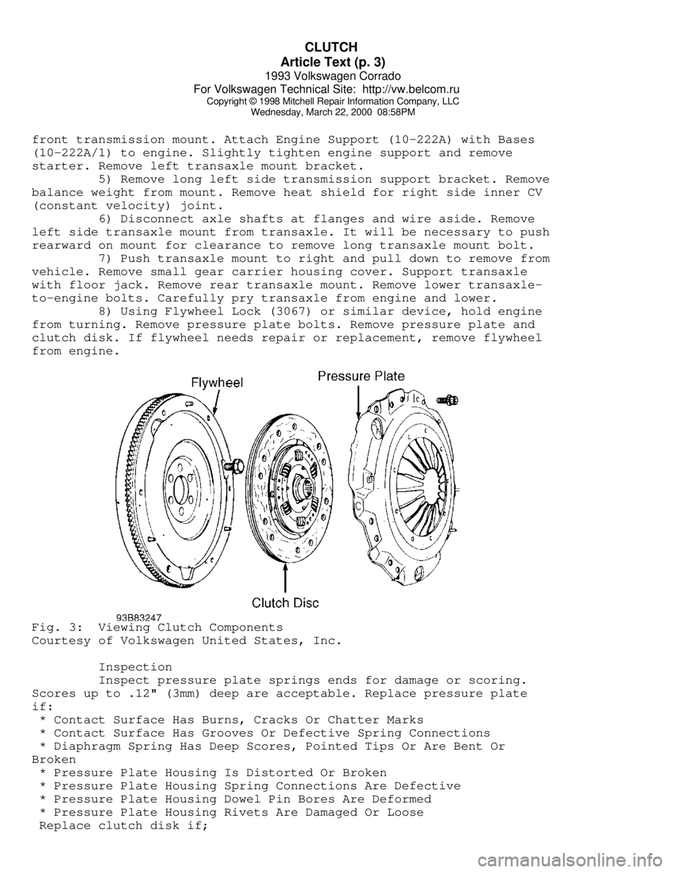
8) Using Flywheel Lock (3067) or similar device, hold engine
from turning. Remove pressure plate bolts. Remove pressure plate and
clutch disk. If flywheel needs repair or replacement, remove flywheel
from engine.Fig. 3: Viewing Clutch Components
Courtesy of Volkswagen United States, Inc.
Inspection
Inspect pressure plate springs ends for damage or scoring.
Scores up to .12" (3mm) deep are acceptable. Replace pressure plate
if:
* Contact Surface Has Burns, Cracks Or Chatter Marks
* Contact Surface Has Grooves Or Defective Spring Connections
* Diaphragm Spring Has Deep Scores, Pointed Tips Or Are Bent Or
Broken
* Pressure Plate Housing Is Distorted Or Broken
* Pressure Plate Housing Spring Connections Are Defective
* Pressure Plate Housing Dowel Pin Bores Are Deformed
* Pressure Plate Housing Rivets Are Damaged Or Loose
Replace clutch disk if;
Page 449 of 920

CLUTCH
Article Text (p. 4)
1993 Volkswagen Corrado
For Volkswagen Technical Site: http://vw.belcom.ru
Copyright © 1998 Mitchell Repair Information Company, LLC
Wednesday, March 22, 2000 08:58PM
* Worn To Surface Of Rivet Heads
* Rivets Are Loose, Missing Or Damaged
* Friction Material Is Oil Or Grease Soaked
* Friction Material Is Loose, Cracked Or Grooved
* Hub Is Rusted Or Damaged
* Springs Are Rusted Solid, Broken, Cracked Or Loose
* Torsion Damper Spring Guide Is Broken
* Torsion Damper Cover Damaged
* Torsion Damper Grooved Or Not Functioning
NOTE: Pressure plate has a protective grease coating. Remove
contact surface grease only. Service life will be shortened
if remaining portions of pressure plate protective grease
are removed.
Installation
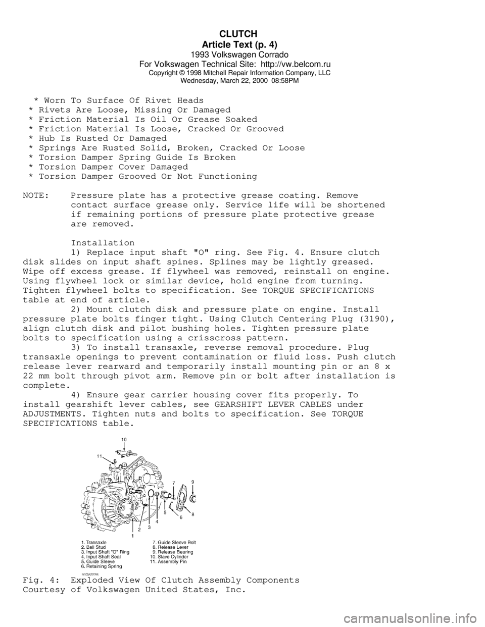
1) Replace input shaft "O" ring. See Fig. 4. Ensure clutch
disk slides on input shaft spines. Splines may be lightly greased.
Wipe off excess grease. If flywheel was removed, reinstall on engine.
Using flywheel lock or similar device, hold engine from turning.
Tighten flywheel bolts to specification. See TORQUE SPECIFICATIONS
table at end of article.
2) Mount clutch disk and pressure plate on engine. Install
pressure plate bolts finger tight. Using Clutch Centering Plug (3190),
align clutch disk and pilot bushing holes. Tighten pressure plate
bolts to specification using a crisscross pattern.
3) To install transaxle, reverse removal procedure. Plug
transaxle openings to prevent contamination or fluid loss. Push clutch
release lever rearward and temporarily install mounting pin or an 8 x
22 mm bolt through pivot arm. Remove pin or bolt after installation is
complete.
4) Ensure gear carrier housing cover fits properly. To
install gearshift lever cables, see GEARSHIFT LEVER CABLES under
ADJUSTMENTS. Tighten nuts and bolts to specification. See TORQUE
SPECIFICATIONS table.Fig. 4: Exploded View Of Clutch Assembly Components
Courtesy of Volkswagen United States, Inc.
Page 733 of 920

STEERING COLUMN
Article Text (p. 2)
1993 Volkswagen Corrado
For Volkswagen Technical Site: http://vw.belcom.ru
Copyright © 1998 Mitchell Repair Information Company, LLC
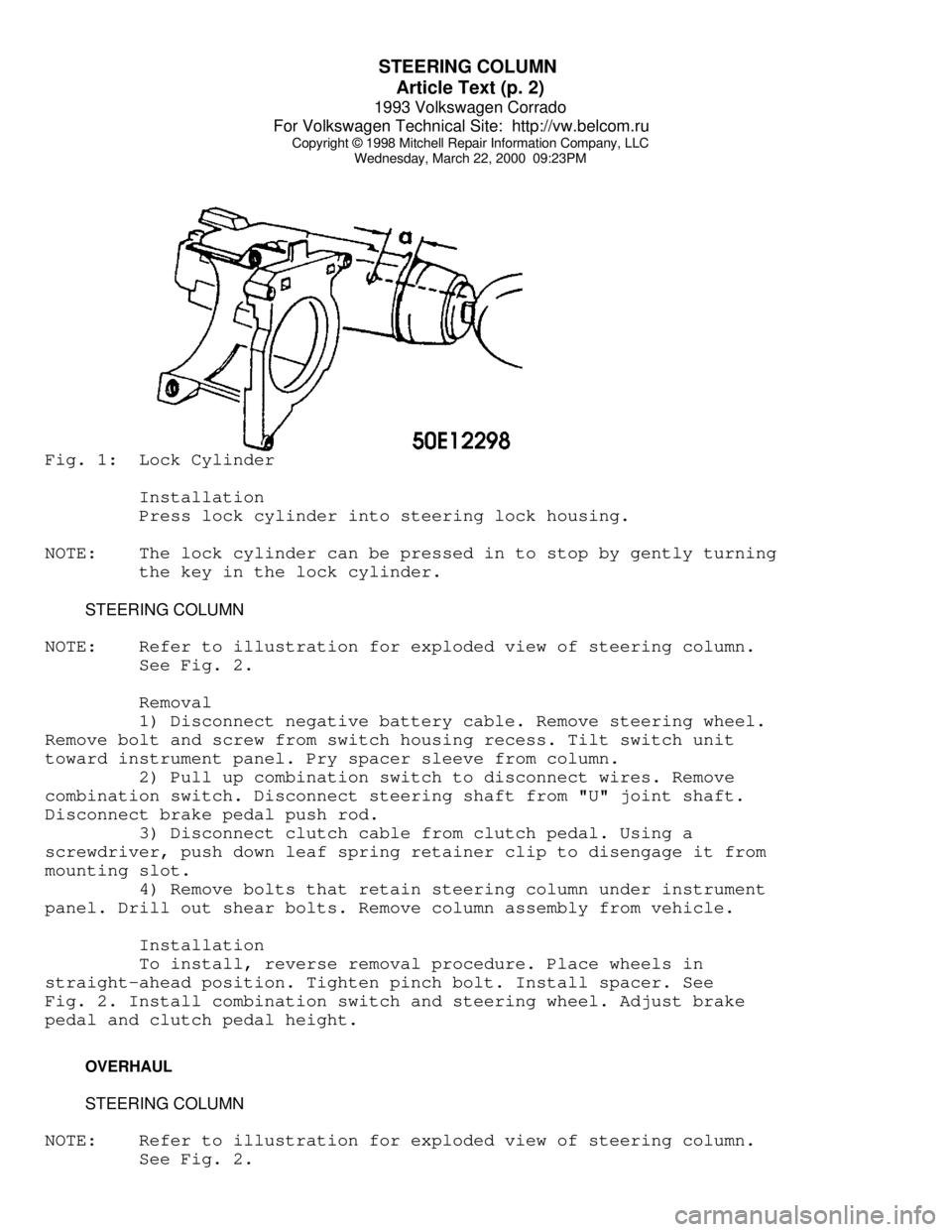
Wednesday, March 22, 2000 09:23PMFig. 1: Lock Cylinder
Installation
Press lock cylinder into steering lock housing.
NOTE: The lock cylinder can be pressed in to stop by gently turning
the key in the lock cylinder.
STEERING COLUMN
NOTE: Refer to illustration for exploded view of steering column.
See Fig. 2.
Removal
1) Disconnect negative battery cable. Remove steering wheel.
Remove bolt and screw from switch housing recess. Tilt switch unit
toward instrument panel. Pry spacer sleeve from column.
2) Pull up combination switch to disconnect wires. Remove
combination switch. Disconnect steering shaft from "U" joint shaft.
Disconnect brake pedal push rod.
3) Disconnect clutch cable from clutch pedal. Using a
screwdriver, push down leaf spring retainer clip to disengage it from
mounting slot.
4) Remove bolts that retain steering column under instrument
panel. Drill out shear bolts. Remove column assembly from vehicle.
Installation
To install, reverse removal procedure. Place wheels in
straight-ahead position. Tighten pinch bolt. Install spacer. See
Fig. 2. Install combination switch and steering wheel. Adjust brake
pedal and clutch pedal height.
OVERHAUL
STEERING COLUMN
NOTE: Refer to illustration for exploded view of steering column.
See Fig. 2.
Page 747 of 920

STEERING GEAR - POWER RACK & PINION
Article Text (p. 4)
1993 Volkswagen Corrado
For Volkswagen Technical Site: http://vw.belcom.ru
Copyright © 1998 Mitchell Repair Information Company, LLC
Wednesday, March 22, 2000 09:23PM
Installation
To install, reverse removal procedure. Tighten nuts and bolts
to specification. See TORQUE SPECIFICATIONS table at end of article.
Fill and bleed hydraulic system. See HYDRAULIC SYSTEM BLEEDING. Check
wheel alignment. See WHEEL ALIGNMENT SPECIFICATIONS & PROCEDURES
article in the WHEEL ALIGNMENT section.
OVERHAUL
Manufacturer recommends that power steering pump and steering
gear be replaced, rather than be repaired.
TORQUE SPECIFICATIONS
TORQUE SPECIFICATIONS TABLEÄÄÄÄÄÄÄÄÄÄÄÄÄÄÄÄÄÄÄÄÄÄÄÄÄÄÄÄÄÄÄÄÄÄÄÄÄÄÄÄÄÄÄÄÄÄÄÄÄÄÄÄÄÄÄÄÄÄÄÄApplication Ft. Lbs. (N.m)
End Housing Bolt ................................. 37 (50)
Power Steering Pump Bolt ......................... 18 (25)
Pressure-Flow Limiting Valve Cap ................. 42 (57)
Pressure Line Fitting ............................ 29 (39)
Return Line Fitting
On Pump ........................................ 29 (39)
On Valve Housing ............................... 22 (30)
Steering Gear Retaining Bolt ..................... 24 (33)
Subframe Bolt
Long .......................................... 96 (130)
Short .......................................... 59 (80)
Tie Rod Lock Nut ................................. 42 (55)
Tie Rod-To-Steering Arm .......................... 32 (44)
Valve Housing Bolt ............................... 15 (20)
ÄÄÄÄÄÄÄÄÄÄÄÄÄÄÄÄÄÄÄÄÄÄÄÄÄÄÄÄÄÄÄÄÄÄÄÄÄÄÄÄÄÄÄÄÄÄÄÄÄÄÄÄÄÄÄÄÄÄÄÄEND OF ARTICLE
Page 756 of 920

SUSPENSION - FRONT
Article Text (p. 2)
1993 Volkswagen Corrado
For Volkswagen Technical Site: http://vw.belcom.ru
Copyright © 1998 Mitchell Repair Information Company, LLC
Wednesday, March 22, 2000 09:24PM
NOTE: See WHEEL ALIGNMENT SPECIFICATIONS & PROCEDURES article in
the WHEEL ALIGNMENT section.
WHEEL BEARING
No adjustment is required.
BALL JOINT CHECKING
Raise and support vehicle. Inspect ball joints for excessive
play and damaged rubber boots. There should be no vertical or
horizontal ball joint play. Replace ball joint if any play is present.
REMOVAL & INSTALLATION
HUB & KNUCKLE ASSEMBLY
Use exploded view illustration when removing or installing
hub and knuckle assembly. See Fig. 1.
LOWER CONTROL ARM & BALL JOINT
Removal
1) Raise and support vehicle. Remove bolt retaining ball
joint at steering knuckle. Separate ball joint from housing. Leave
control arm hanging in mounts at subframe.
2) If control arm is not to be removed and ball joint is
riveted to control arm, drill out ball joint rivets using a 9/32" (7
mm) drill. After drilling rivets, chisel off rivet heads (if
necessary). If ball joint is bolted to control arm, remove bolts.
Remove ball joint.
3) If control arm is to be removed from vehicle, remove
stabilizer bar link rod nut, washers, and bushings. Remove pivot bolt
and "U" bracket housing inner pivot pin. Slide out control arm.
NOTE: On vehicles with automatic transmission, engine may have to
be lifted slightly to gain access to pivot bolts.
Inspection
Check lower control arm bushings for excessive wear, cracks
or contamination. Replace bushings if necessary. To replace bushings,
press out worn bushing. Select new bushing and press into position.
Ensure bushing does not twist when seating into place.
Installation
Slide new ball joint into slot in control arm. Install and
tighten ball joint retaining bolts. Install lower control arm to
subframe. Install ball joint into steering knuckle. To complete
installation, reverse removal procedure. Tighten control arm bolts
with vehicle on ground. Tighten all bolts and nuts to specification.
See TORQUE SPECIFICATIONS table at end of article. Check wheel