1993 VOLKSWAGEN CORRADO key
[x] Cancel search: keyPage 83 of 920

* ELECTRICAL SYSTEM UNIFORM INSPECTION GUIDELINES *
Article Text (p. 18)
1993 Volkswagen Corrado
For Volkswagen Technical Site: http://vw.belcom.ru
Copyright © 1998 Mitchell Repair Information Company, LLC
Wednesday, March 22, 2000 08:34PM
terminals ³ ³
ÄÄÄÄÄÄÄÄÄÄÄÄÄÄÄÄÄÄÄÄÄ´
³Damaged
³ ³
ÄÄÄÄÄÄÄÄÄÄÄÄÄÄÄÄÄÄÄÄÄÁÄÄÄÄÄÄÄÄÄÄÄÄÄÄÄÄÄÄÄÄÄÄÁÄÄÄÄÄÄÄÄÄÄÄÄÄÄÄÄÄÄÄÄÄÄÄÄÄ VEHICLE ACCESSORIES
Vehicle accessories refers to OEM installed equipment,
including but not limited to power windows, locks, seats, roof/top,
antennas, heated seats, mirrors, windshield/window defrosters, trunk
pull down/release, keyless entry, tire pressure monitors, electric
mirrors, etc.
POWER LOCKS, WINDOWS, SEATS, MIRRORS, ROOF/TOPS, ANTENNAS,
SLIDING DOORS
SWITCHES
ÄÄÄÄÄÄÄÄÄÄÄÄÄÄÄÄÄÄÄÄÄÄÄÄÄÄÄÄÄÄÄÄÄÄÄÄÄÂÄÄÄÄÄÄÄÄÄÄÄÄÄÄÄÄÄÄÄÄÄÄÄÄÄÄÄÄÄÄÄÄCondition
³ Procedure
ÄÄÄÄÄÄÄÄÄÄÄÄÄÄÄÄÄÄÄÄÄÄÄÄÄÄÄÄÄÄÄÄÄÄÄÄÄÅÄÄÄÄÄÄÄÄÄÄÄÄÄÄÄÄÄÄÄÄÄÄÄÄÄÄÄÄÄÄÄÄInoperable
³ Require replacement.
ÄÄÄÄÄÄÄÄÄÄÄÄÄÄÄÄÄÄÄÄÄÄÄÄÄÄÄÄÄÄÄÄÄÄÄÄÄÅÄÄÄÄÄÄÄÄÄÄÄÄÄÄÄÄÄÄÄÄÄÄÄÄÄÄÄÄÄÄÄÄIntermittent
³ Suggest replacement.
ÄÄÄÄÄÄÄÄÄÄÄÄÄÄÄÄÄÄÄÄÄÄÄÄÄÄÄÄÄÄÄÄÄÄÄÄÄÅÄÄÄÄÄÄÄÄÄÄÄÄÄÄÄÄÄÄÄÄÄÄÄÄÄÄÄÄÄÄÄÄMalfunctioning (e.g.,binding, worn,
³ Suggest repair or replacement.
won't return, etc.)
³
ÄÄÄÄÄÄÄÄÄÄÄÄÄÄÄÄÄÄÄÄÄÄÄÄÄÄÄÄÄÄÄÄÄÄÄÄÄÅÄÄÄÄÄÄÄÄÄÄÄÄÄÄÄÄÄÄÄÄÄÄÄÄÄÄÄÄÄÄÄÄMissing
³ Require replacement.
ÄÄÄÄÄÄÄÄÄÄÄÄÄÄÄÄÄÄÄÄÄÄÄÄÄÄÄÄÄÄÄÄÄÄÄÄÄÅÄÄÄÄÄÄÄÄÄÄÄÄÄÄÄÄÄÄÄÄÄÄÄÄÄÄÄÄÄÄÄÄMissing, damaged mounting hardware
³ Require repair or replacement
³ of mounting hardware.
ÄÄÄÄÄÄÄÄÄÄÄÄÄÄÄÄÄÄÄÄÄÄÄÄÄÄÄÄÄÄÄÄÄÄÄÄÄÅÄÄÄÄÄÄÄÄÄÄÄÄÄÄÄÄÄÄÄÄÄÄÄÄÄÄÄÄÄÄÄÄCorroded, loose terminals
³ Suggest repair or replacement.
ÄÄÄÄÄÄÄÄÄÄÄÄÄÄÄÄÄÄÄÄÄÄÄÄÄÄÄÄÄÄÄÄÄÄÄÄÄÅÄÄÄÄÄÄÄÄÄÄÄÄÄÄÄÄÄÄÄÄÄÄÄÄÄÄÄÄÄÄÄÄDamaged (e.g., melted, burned,
³ Suggest replacement.
cracked, etc.)
³
ÄÄÄÄÄÄÄÄÄÄÄÄÄÄÄÄÄÄÄÄÄÄÄÄÄÄÄÄÄÄÄÄÄÄÄÄÄÁÄÄÄÄÄÄÄÄÄÄÄÄÄÄÄÄÄÄÄÄÄÄÄÄÄÄÄÄÄÄÄÄ ACTUATORS/MOTORS/SOLENOIDS/TRANSDUCERS
ACTUATORS/MOTORS/SOLENOIDS/TRANSDUCERS
ÄÄÄÄÄÄÄÄÄÄÄÄÄÄÄÄÄÄÄÄÄÂÄÄÄÄÄÄÄÄÄÄÄÄÄÄÄÄÄÄÄÄÄÄÂÄÄÄÄÄÄÄÄÄÄÄÄÄÄÄÄÄÄÄÄÄÄÄÄÄCondition
³ Procedure ³ Note
ÄÄÄÄÄÄÄÄÄÄÄÄÄÄÄÄÄÄÄÄÄÅÄÄÄÄÄÄÄÄÄÄÄÄÄÄÄÄÄÄÄÄÄÄÅÄÄÄÄÄÄÄÄÄÄÄÄÄÄÄÄÄÄÄÄÄÄÄÄÄInoperative/
³ Require replacement. ³intermittent
³ ³
ÄÄÄÄÄÄÄÄÄÄÄÄÄÄÄÄÄÄÄÄÄÅÄÄÄÄÄÄÄÄÄÄÄÄÄÄÄÄÄÄÄÄÄÄÅÄÄÄÄÄÄÄÄÄÄÄÄÄÄÄÄÄÄÄÄÄÄÄÄÄMalfunctioning (e.g.
³ Suggest repair or ³binding, worn, won't
³ replacement. ³return, etc.)
³ ³
ÄÄÄÄÄÄÄÄÄÄÄÄÄÄÄÄÄÄÄÄÄÅÄÄÄÄÄÄÄÄÄÄÄÄÄÄÄÄÄÄÄÄÄÄÅÄÄÄÄÄÄÄÄÄÄÄÄÄÄÄÄÄÄÄÄÄÄÄÄÄMissing
³ Require replacement. ³
Page 92 of 920

* ELECTRICAL SYSTEM UNIFORM INSPECTION GUIDELINES *
Article Text (p. 27)
1993 Volkswagen Corrado
For Volkswagen Technical Site: http://vw.belcom.ru
Copyright © 1998 Mitchell Repair Information Company, LLC
Wednesday, March 22, 2000 08:34PM
Condition ³ Procedure
ÄÄÄÄÄÄÄÄÄÄÄÄÄÄÄÄÄÄÄÄÄÄÄÄÄÄÄÄÄÄÄÄÄÄÄÄÄÅÄÄÄÄÄÄÄÄÄÄÄÄÄÄÄÄÄÄÄÄÄÄÄÄÄÄÄÄÄÄÄÄInoperative
³ Require repair or replacement.
ÄÄÄÄÄÄÄÄÄÄÄÄÄÄÄÄÄÄÄÄÄÄÄÄÄÄÄÄÄÄÄÄÄÄÄÄÄÅÄÄÄÄÄÄÄÄÄÄÄÄÄÄÄÄÄÄÄÄÄÄÄÄÄÄÄÄÄÄÄÄIntermittent
³
ÄÄÄÄÄÄÄÄÄÄÄÄÄÄÄÄÄÄÄÄÄÄÄÄÄÄÄÄÄÄÄÄÄÄÄÄÄ´ Suggest repair or replacement.
Malfunctioning
³
ÄÄÄÄÄÄÄÄÄÄÄÄÄÄÄÄÄÄÄÄÄÄÄÄÄÄÄÄÄÄÄÄÄÄÄÄÄÅÄÄÄÄÄÄÄÄÄÄÄÄÄÄÄÄÄÄÄÄÄÄÄÄÄÄÄÄÄÄÄÄMissing
³ Require replacement.
ÄÄÄÄÄÄÄÄÄÄÄÄÄÄÄÄÄÄÄÄÄÄÄÄÄÄÄÄÄÄÄÄÄÄÄÄÄÅÄÄÄÄÄÄÄÄÄÄÄÄÄÄÄÄÄÄÄÄÄÄÄÄÄÄÄÄÄÄÄÄMissing, damaged mounting hardware
³ Require repair or replacement
³ of mounting hardware.
ÄÄÄÄÄÄÄÄÄÄÄÄÄÄÄÄÄÄÄÄÄÄÄÄÄÄÄÄÄÄÄÄÄÄÄÄÄÅÄÄÄÄÄÄÄÄÄÄÄÄÄÄÄÄÄÄÄÄÄÄÄÄÄÄÄÄÄÄÄÄCorroded, loose terminals
³
ÄÄÄÄÄÄÄÄÄÄÄÄÄÄÄÄÄÄÄÄÄÄÄÄÄÄÄÄÄÄÄÄÄÄÄÄÄ´ Suggest repair or replacement.
Damaged
³
ÄÄÄÄÄÄÄÄÄÄÄÄÄÄÄÄÄÄÄÄÄÄÄÄÄÄÄÄÄÄÄÄÄÄÄÄÄÁÄÄÄÄÄÄÄÄÄÄÄÄÄÄÄÄÄÄÄÄÄÄÄÄÄÄÄÄÄÄÄÄ SECURITY/ALARM SYSTEM/SENSORS
SECURITY/ALARM SYSTEM/SENSORS
ÄÄÄÄÄÄÄÄÄÄÄÄÄÄÄÄÄÄÄÄÄÄÄÄÄÄÄÄÄÄÄÄÄÄÄÄÄÂÄÄÄÄÄÄÄÄÄÄÄÄÄÄÄÄÄÄÄÄÄÄÄÄÄÄÄÄÄÄÄÄCondition
³ Procedure
ÄÄÄÄÄÄÄÄÄÄÄÄÄÄÄÄÄÄÄÄÄÄÄÄÄÄÄÄÄÄÄÄÄÄÄÄÄÅÄÄÄÄÄÄÄÄÄÄÄÄÄÄÄÄÄÄÄÄÄÄÄÄÄÄÄÄÄÄÄÄInoperative
³ Require repair or replacement.
ÄÄÄÄÄÄÄÄÄÄÄÄÄÄÄÄÄÄÄÄÄÄÄÄÄÄÄÄÄÄÄÄÄÄÄÄÄÅÄÄÄÄÄÄÄÄÄÄÄÄÄÄÄÄÄÄÄÄÄÄÄÄÄÄÄÄÄÄÄÄIntermittent
³
ÄÄÄÄÄÄÄÄÄÄÄÄÄÄÄÄÄÄÄÄÄÄÄÄÄÄÄÄÄÄÄÄÄÄÄÄÄ´ Suggest repair or replacement.
Malfunctioning
³
ÄÄÄÄÄÄÄÄÄÄÄÄÄÄÄÄÄÄÄÄÄÄÄÄÄÄÄÄÄÄÄÄÄÄÄÄÄÅÄÄÄÄÄÄÄÄÄÄÄÄÄÄÄÄÄÄÄÄÄÄÄÄÄÄÄÄÄÄÄÄMissing
³ Require replacement.
ÄÄÄÄÄÄÄÄÄÄÄÄÄÄÄÄÄÄÄÄÄÄÄÄÄÄÄÄÄÄÄÄÄÄÄÄÄÅÄÄÄÄÄÄÄÄÄÄÄÄÄÄÄÄÄÄÄÄÄÄÄÄÄÄÄÄÄÄÄÄMissing, damaged mounting hardware
³ Require repair or replacement
³ of mounting hardware.
ÄÄÄÄÄÄÄÄÄÄÄÄÄÄÄÄÄÄÄÄÄÄÄÄÄÄÄÄÄÄÄÄÄÄÄÄÄÅÄÄÄÄÄÄÄÄÄÄÄÄÄÄÄÄÄÄÄÄÄÄÄÄÄÄÄÄÄÄÄÄCorroded, loose terminals
³
ÄÄÄÄÄÄÄÄÄÄÄÄÄÄÄÄÄÄÄÄÄÄÄÄÄÄÄÄÄÄÄÄÄÄÄÄÄ´ Suggest repair or replacement.
Damaged
³
ÄÄÄÄÄÄÄÄÄÄÄÄÄÄÄÄÄÄÄÄÄÄÄÄÄÄÄÄÄÄÄÄÄÄÄÄÄÁÄÄÄÄÄÄÄÄÄÄÄÄÄÄÄÄÄÄÄÄÄÄÄÄÄÄÄÄÄÄÄÄ KEYLESS ENTRY/KEY PAD/TRANSMITTER
KEYLESS ENTRY/KEY PAD/TRANSMITTER
ÄÄÄÄÄÄÄÄÄÄÄÄÄÄÄÄÄÄÄÄÄÄÄÄÄÄÄÄÄÄÄÄÄÄÄÄÄÂÄÄÄÄÄÄÄÄÄÄÄÄÄÄÄÄÄÄÄÄÄÄÄÄÄÄÄÄÄÄÄÄCondition
³ Procedure
ÄÄÄÄÄÄÄÄÄÄÄÄÄÄÄÄÄÄÄÄÄÄÄÄÄÄÄÄÄÄÄÄÄÄÄÄÄÅÄÄÄÄÄÄÄÄÄÄÄÄÄÄÄÄÄÄÄÄÄÄÄÄÄÄÄÄÄÄÄÄInoperative/intermittent
³ Require repair or replacement.
ÄÄÄÄÄÄÄÄÄÄÄÄÄÄÄÄÄÄÄÄÄÄÄÄÄÄÄÄÄÄÄÄÄÄÄÄÄÅÄÄÄÄÄÄÄÄÄÄÄÄÄÄÄÄÄÄÄÄÄÄÄÄÄÄÄÄÄÄÄÄMalfunctioning
³ Suggest repair or replacement.
ÄÄÄÄÄÄÄÄÄÄÄÄÄÄÄÄÄÄÄÄÄÄÄÄÄÄÄÄÄÄÄÄÄÄÄÄÄÅÄÄÄÄÄÄÄÄÄÄÄÄÄÄÄÄÄÄÄÄÄÄÄÄÄÄÄÄÄÄÄÄMissing
³ Require replacement.
ÄÄÄÄÄÄÄÄÄÄÄÄÄÄÄÄÄÄÄÄÄÄÄÄÄÄÄÄÄÄÄÄÄÄÄÄÄÅÄÄÄÄÄÄÄÄÄÄÄÄÄÄÄÄÄÄÄÄÄÄÄÄÄÄÄÄÄÄÄÄ
Page 338 of 920
A/C COMPRESSOR SERVICING
Article Text (p. 2)
1993 Volkswagen Corrado
For Volkswagen Technical Site: http://vw.belcom.ru
Copyright © 1998 Mitchell Repair Information Company, LLC
Wednesday, March 22, 2000 08:48PM
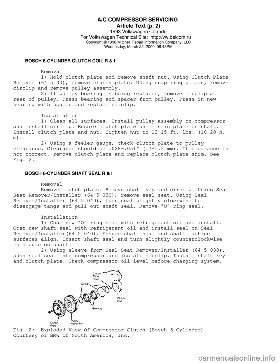
BOSCH 6-CYLINDER CLUTCH COIL R & I
Removal
1) Hold clutch plate and remove shaft nut. Using Clutch Plate
Remover (64 5 00), remove clutch plate. Using snap ring pliers, remove
circlip and remove pulley assembly.
2) If pulley bearing is being replaced, remove circlip at
rear of pulley. Press bearing and spacer from pulley. Press in new
bearing with spacer and replace circlip.
Installation
1) Clean all surfaces. Install pulley assembly on compressor
and install circlip. Ensure clutch plate shim is in place on shaft.
Install clutch plate and nut. Tighten nut to 13-15 ft. lbs. (18-20 N.
m).
2) Using a feeler gauge, check clutch plate-to-pulley
clearance. Clearance should be .028-.051" (.7-1.3 mm). If clearance is
not correct, remove clutch plate and replace clutch plate shim. See
Fig. 2.
BOSCH 6-CYLINDER SHAFT SEAL R & I
Removal
Remove clutch plate. Remove shaft key and circlip. Using Seal
Seat Remover/Installer (64 5 030), remove seal seat. Using Seal
Remover/Installer (64 5 040), turn seal slightly clockwise to
disengage tangs and pull out shaft seal. Remove "O" ring seal.
Installation
1) Coat new "O" ring seal with refrigerant oil and install.
Coat new shaft seal with refrigerant oil and install seal on Seal
Remover/Installer(64 5 040). Ensure shaft seal and shaft machine
surfaces align. Insert shaft seal and turn slightly counterclockwise
to secure on shaft.
2) Using sleeve from Seal Seat Remover/Installer (64 5 030),
push seal seat into compressor and install circlip. Install shaft key
and clutch plate. Check compressor oil level before charging system.Fig. 2: Exploded View Of Compressor Clutch (Bosch 6-Cylinder)
Courtesy of BMW of North America, Inc.
Page 345 of 920
A/C COMPRESSOR SERVICING
Article Text (p. 9)
1993 Volkswagen Corrado
For Volkswagen Technical Site: http://vw.belcom.ru
Copyright © 1998 Mitchell Repair Information Company, LLC
Wednesday, March 22, 2000 08:48PM
into remover body to remove clutch plate and hub assembly. Remove
shaft key and save for installation.
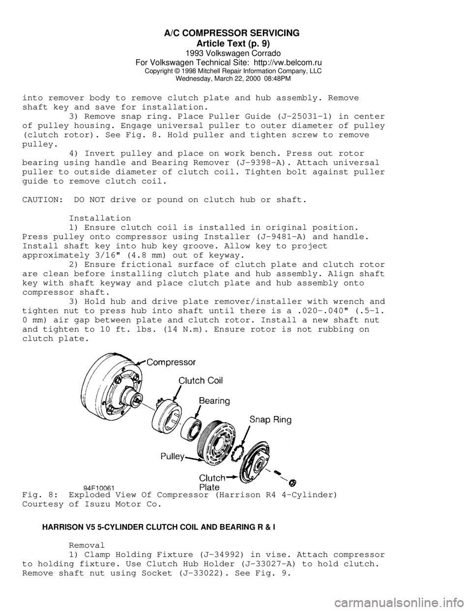
3) Remove snap ring. Place Puller Guide (J-25031-1) in center
of pulley housing. Engage universal puller to outer diameter of pulley
(clutch rotor). See Fig. 8. Hold puller and tighten screw to remove
pulley.
4) Invert pulley and place on work bench. Press out rotor
bearing using handle and Bearing Remover (J-9398-A). Attach universal
puller to outside diameter of clutch coil. Tighten bolt against puller
guide to remove clutch coil.
CAUTION: DO NOT drive or pound on clutch hub or shaft.
Installation
1) Ensure clutch coil is installed in original position.
Press pulley onto compressor using Installer (J-9481-A) and handle.
Install shaft key into hub key groove. Allow key to project
approximately 3/16" (4.8 mm) out of keyway.
2) Ensure frictional surface of clutch plate and clutch rotor
are clean before installing clutch plate and hub assembly. Align shaft
key with shaft keyway and place clutch plate and hub assembly onto
compressor shaft.
3) Hold hub and drive plate remover/installer with wrench and
tighten nut to press hub into shaft until there is a .020-.040" (.5-1.
0 mm) air gap between plate and clutch rotor. Install a new shaft nut
and tighten to 10 ft. lbs. (14 N.m). Ensure rotor is not rubbing on
clutch plate.Fig. 8: Exploded View Of Compressor (Harrison R4 4-Cylinder)
Courtesy of Isuzu Motor Co.
HARRISON V5 5-CYLINDER CLUTCH COIL AND BEARING R & I
Removal
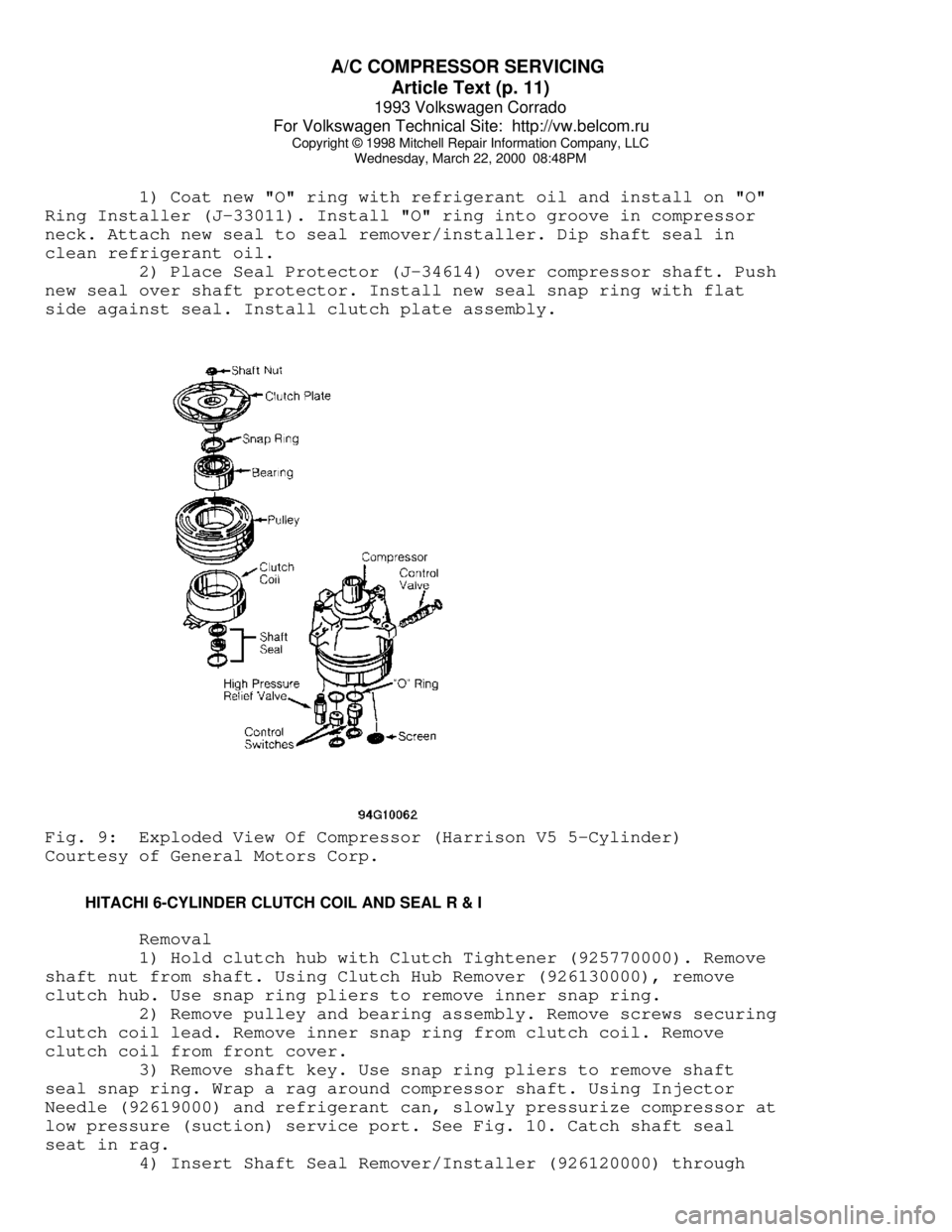
1) Clamp Holding Fixture (J-34992) in vise. Attach compressor
to holding fixture. Use Clutch Hub Holder (J-33027-A) to hold clutch.
Remove shaft nut using Socket (J-33022). See Fig. 9.
Page 346 of 920

A/C COMPRESSOR SERVICING
Article Text (p. 10)
1993 Volkswagen Corrado
For Volkswagen Technical Site: http://vw.belcom.ru
Copyright © 1998 Mitchell Repair Information Company, LLC
Wednesday, March 22, 2000 08:48PM
2) Thread Clutch Plate and Hub Assembly Remover (J-33013-B)
into hub. Hold body of remover with wrench and turn center bolt to
remove clutch plate and hub assembly. Remove snap ring. Remove shaft
key and save for installation.
3) Place Puller Guide (J-33023-A) in center of pulley
housing. Engage Rotor/Bearing Puller (J-33020) to inner circle of
slots in pulley (rotor). Hold rotor/bearing puller in place and
tighten screw to remove pulley.
4) Remove screw from rotor/bearing puller. Invert assembly
and place on work bench with rotor/bearing puller still engaged.
Remove hub bearing using handle and Bearing Remover (J-9398-A).
5) With puller guide in place, attach Crossbar (J-8433-1) and
Puller (J-33025) to outside diameter of clutch coil. Tighten crossbar
Bolt (J-8433-3) against puller guide to remove clutch coil.
Installation
1) Ensure clutch coil is installed in original position.
Press coil into position using crossbar, clutch Coil Installer (J-
33024) and Through Bolts (J-34992-2). Stake compressor housing 120
degrees apart to secure coil.
2) Position Rotor/Bearing Installer (J-33017) and puller
guide over inner race of bearing. Using through bolts, assemble
crossbar over puller pilot and tighten through bolts onto holding
fixture. Tighten crossbar bolt to press pulley/bearing assembly onto
compressor.
3) Install shaft key into hub key groove. Allow key to
project approximately 1/8" (3.2 mm) out of keyway. Align shaft key
with shaft keyway and place clutch plate and hub assembly onto
compressor shaft.
CAUTION: Do not drive or pound on clutch hub or compressor shaft, as
compressor could be damaged internally.
4) Hold hex portion of Hub Installer (J-33013) with a wrench.
Tighten center screw to press hub into shaft until there is .020-.030"
(.50-.76 mm) air gap between frictional plate and clutch rotor.
5) Install new shaft nut with small diameter boss of nut
against crankshaft shoulder. Use Socket (J-33022) and Clutch Hub
Holder (J-33027-A). Tighten shaft nut to 12 ft. lbs. (16 N.m). Ensure
pulley does not rub on clutch plate. See Fig. 9.
HARRISON V5 5-CYLINDER SHAFT SEAL R & I
Removal
Remove clutch plate and hub assembly. Remove shaft seal snap
ring. Thoroughly clean inside of compressor neck area around shaft and
seal. Engage tangs of Seal Remover/Installer (J-23128-A) into recessed
portion of seal and remove seal. Remove and discard "O" ring from
compressor neck. Thoroughly clean inside of compressor neck and "O"
ring groove.
Installation
Page 347 of 920
A/C COMPRESSOR SERVICING
Article Text (p. 11)
1993 Volkswagen Corrado
For Volkswagen Technical Site: http://vw.belcom.ru
Copyright © 1998 Mitchell Repair Information Company, LLC
Wednesday, March 22, 2000 08:48PM
1) Coat new "O" ring with refrigerant oil and install on "O"
Ring Installer (J-33011). Install "O" ring into groove in compressor
neck. Attach new seal to seal remover/installer. Dip shaft seal in
clean refrigerant oil.
2) Place Seal Protector (J-34614) over compressor shaft. Push
new seal over shaft protector. Install new seal snap ring with flat
side against seal. Install clutch plate assembly.Fig. 9: Exploded View Of Compressor (Harrison V5 5-Cylinder)
Courtesy of General Motors Corp.
HITACHI 6-CYLINDER CLUTCH COIL AND SEAL R & I
Removal
1) Hold clutch hub with Clutch Tightener (925770000). Remove
shaft nut from shaft. Using Clutch Hub Remover (926130000), remove
clutch hub. Use snap ring pliers to remove inner snap ring.
2) Remove pulley and bearing assembly. Remove screws securing
clutch coil lead. Remove inner snap ring from clutch coil. Remove
clutch coil from front cover.
3) Remove shaft key. Use snap ring pliers to remove shaft
seal snap ring. Wrap a rag around compressor shaft. Using Injector
Needle (92619000) and refrigerant can, slowly pressurize compressor at
low pressure (suction) service port. See Fig. 10. Catch shaft seal
seat in rag.
4) Insert Shaft Seal Remover/Installer (926120000) through
Page 351 of 920
A/C COMPRESSOR SERVICING
Article Text (p. 15)
1993 Volkswagen Corrado
For Volkswagen Technical Site: http://vw.belcom.ru
Copyright © 1998 Mitchell Repair Information Company, LLC
Wednesday, March 22, 2000 08:48PM
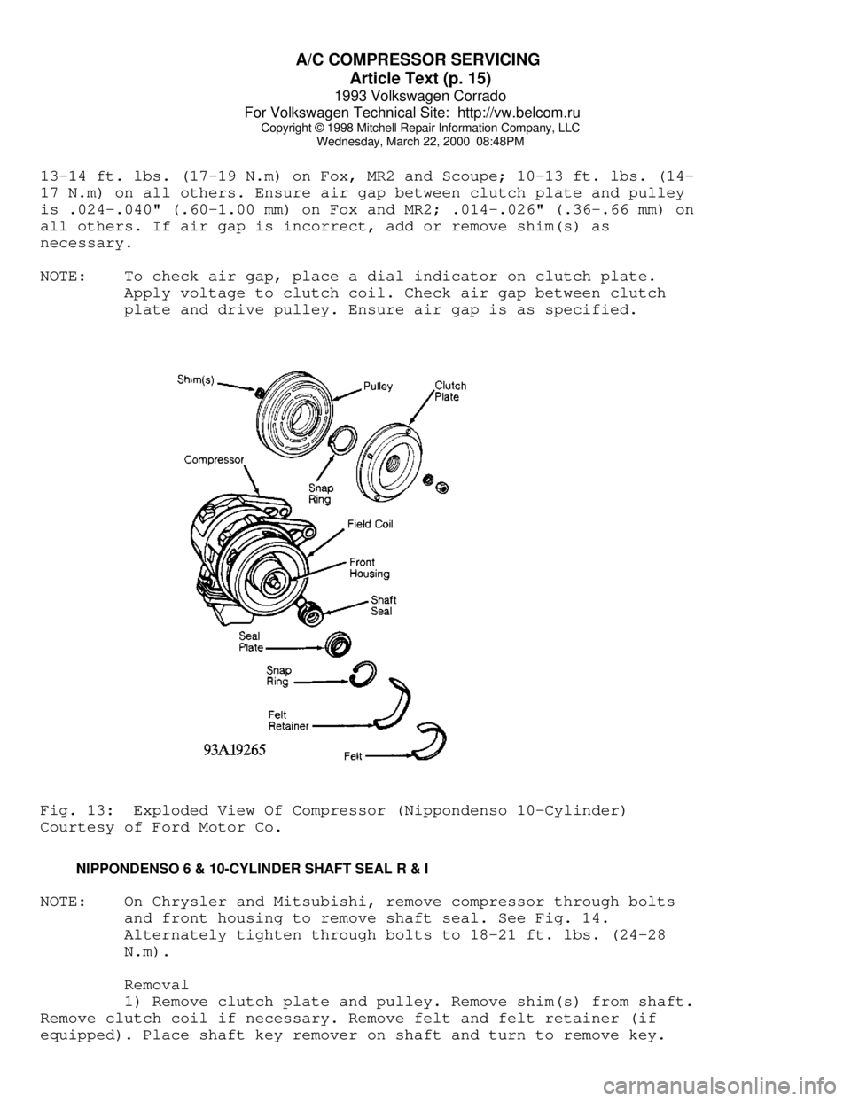
13-14 ft. lbs. (17-19 N.m) on Fox, MR2 and Scoupe; 10-13 ft. lbs. (14-
17 N.m) on all others. Ensure air gap between clutch plate and pulley
is .024-.040" (.60-1.00 mm) on Fox and MR2; .014-.026" (.36-.66 mm) on
all others. If air gap is incorrect, add or remove shim(s) as
necessary.
NOTE: To check air gap, place a dial indicator on clutch plate.
Apply voltage to clutch coil. Check air gap between clutch
plate and drive pulley. Ensure air gap is as specified.Fig. 13: Exploded View Of Compressor (Nippondenso 10-Cylinder)
Courtesy of Ford Motor Co.
NIPPONDENSO 6 & 10-CYLINDER SHAFT SEAL R & I
NOTE: On Chrysler and Mitsubishi, remove compressor through bolts
and front housing to remove shaft seal. See Fig. 14.
Alternately tighten through bolts to 18-21 ft. lbs. (24-28
N.m).
Removal
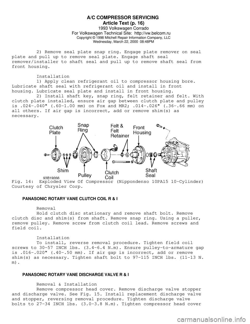
1) Remove clutch plate and pulley. Remove shim(s) from shaft.
Remove clutch coil if necessary. Remove felt and felt retainer (if
equipped). Place shaft key remover on shaft and turn to remove key.
Page 352 of 920
A/C COMPRESSOR SERVICING
Article Text (p. 16)
1993 Volkswagen Corrado
For Volkswagen Technical Site: http://vw.belcom.ru
Copyright © 1998 Mitchell Repair Information Company, LLC
Wednesday, March 22, 2000 08:48PM
2) Remove seal plate snap ring. Engage plate remover on seal
plate and pull up to remove seal plate. Engage shaft seal
remover/installer to shaft seal and pull up to remove shaft seal from
front housing.
Installation
1) Apply clean refrigerant oil to compressor housing bore.
Lubricate shaft seal with refrigerant oil and install in front
housing. Lubricate seal plate and install in front housing.
2) Install shaft key, snap ring, felt retainer and felt. With
clutch plate installed, ensure air gap between clutch plate and pulley
is .024-.040" (.60-1.00 mm) on Fox and MR2; .014-.026" (.36-.66 mm) on
all others. If air gap is incorrect, add or remove shim(s) as
necessary.Fig. 14: Exploded View Of Compressor (Nippondenso 10PA15 10-Cylinder)
Courtesy of Chrysler Corp.
PANASONIC ROTARY VANE CLUTCH COIL R & I
Removal
Hold clutch disc stationary and remove shaft bolt. Remove
clutch disc and shim(s) from shaft. Remove snap ring. Using a puller,
remove pulley. Remove screw from clutch coil lead. Remove screws and
field coil.
Installation
To install, reverse removal procedure. Tighten field coil
screws to 30-57 INCH lbs. (3.4-6.4 N.m). Ensure pulley-to-armature gap
is .016-.020" (.40-.50 mm). If air gap is incorrect, add or remove
shim(s) as necessary. Tighten shaft bolt to 97-115 INCH lbs. (11-13 N.
m).
PANASONIC ROTARY VANE DISCHARGE VALVE R & I
Removal & Installation
Remove compressor head cover. Remove discharge valve stopper
and discharge valve. See Fig. 15. Install replacement discharge valve
and stopper, reversing removal procedure. Tighten discharge valve
bolts to 27-34 INCH lbs. (3.0-3.8 N.m). Tighten compressor head cover