1993 VOLKSWAGEN CORRADO alternator
[x] Cancel search: alternatorPage 1 of 920

1993 Volkswagen Corrado All Categories All Sections
Title List for Volkswagen Technical Site: http://vw.belcom.ru
Copyright © 1998 Mitchell Repair Information Company, LLC
Wednesday, March 22, 2000 09:28PM* A/C-HEATER SYSTEM UNIFORM INSPECTION GUIDELINES ** ANTI-LOCK BRAKES UNIFORM INSPECTION GUIDELINE ** AUTO TRANS DIAGNOSIS MENU - VOLKSWAGEN* BRAKE SYSTEM UNIFORM INSPECTION GUIDELINES ** ELECTRICAL SYSTEM UNIFORM INSPECTION GUIDELINES ** ENGINE SYSTEMS UNIFORM INSPECTION GUIDELINES ** EXHAUST SYSTEM UNIFORM INSPECTION GUIDELINES ** STEERING UNIFORM INSPECTION GUIDELINES ** SUSPENSION UNIFORM INSPECTION GUIDELINES ** SYMPTOM CHECK LIST *2.8L IN-LINE V6 (VR6)A - ENGINE/VIN IDA/C COMPRESSOR OIL CHECKINGA/C COMPRESSOR SERVICINGA/C SYSTEM GENERAL DIAGNOSTIC PROCEDURESA/C SYSTEM GENERAL SERVICINGA/C-HEATER SYSTEM - MANUALAA - USING THIS SECTION (GENERAL HELP INFORMATION)ABBREVIATIONSALTERNATOR & REGULATORANTI-LOCK BRAKE SAFETY PRECAUTIONSANTI-LOCK BRAKE SYSTEMANTI-THEFT SYSTEMAXLE SHAFTSB - EMISSION APPLICATIONBRAKE SYSTEMC - SPECIFICATIONSCLUTCHCOMPUTER RELEARN PROCEDURESCRUISE CONTROL SYSTEMD - ADJUSTMENTSDEFOGGER - REAR WINDOWDOOR LOCKS - POWERE - THEORY/OPERATIONELECTRICAL COMPONENT LOCATORELECTROSTATIC DISCHARGE WARNING - BASIC INFORMATIONEMISSION CONTROL VISUAL INSPECTION PROCEDURESENGINE OVERHAUL PROCEDURES - GENERAL INFORMATIONF - BASIC TESTINGFAULTY RADIATOR FAN MOTOR COULD OVERHEAT & STALL ENGFUSES & CIRCUIT BREAKERSG - TESTS W/CODESGEAR TOOTH CONTACT PATTERNSGENERAL COOLING SYSTEM SERVICINGH - TESTS W/O CODES
Page 72 of 920

* ELECTRICAL SYSTEM UNIFORM INSPECTION GUIDELINES *
Article Text (p. 7)
1993 Volkswagen Corrado
For Volkswagen Technical Site: http://vw.belcom.ru
Copyright © 1998 Mitchell Repair Information Company, LLC
Wednesday, March 22, 2000 08:34PM
³ ³ indicates low fluid level
³ ³ require replacement.
ÄÄÄÄÄÄÄÄÄÄÄÄÄÄÄÄÄÄÄÄÅÄÄÄÄÄÄÄÄÄÄÄÄÄÄÄÄÄÄÄÄÄÄÅÄÄÄÄÄÄÄÄÄÄÄÄÄÄÄÄÄÄÄÄÄÄÄÄÄÄSwollen casing
³ Further inspection ³ No service suggested or
³ required. ³ required unless the
ÄÄÄÄÄÄÄÄÄÄÄÄÄÄÄÄÄÄÄÄ´ ³ battery fails load test
Electrolyte
³ ³ or fails to accept or
discoloration/
³ ³ hold a charge -
contamination
³ ³ replacement required.
ÄÄÄÄÄÄÄÄÄÄÄÄÄÄÄÄÄÄÄÄÅÄÄÄÄÄÄÄÄÄÄÄÄÄÄÄÄÄÄÄÄÄÄÅÄÄÄÄÄÄÄÄÄÄÄÄÄÄÄÄÄÄÄÄÄÄÄÄÄÄWet/dirty top
³ Clean battery using ³ Check fluid level and
³ BCI procedures. ³ adjust to manufacturer's
³ Further inspection ³ specification. Check
³ required. ³ charging system for
³ ³ proper operation.
ÄÄÄÄÄÄÄÄÄÄÄÄÄÄÄÄÄÄÄÄÅÄÄÄÄÄÄÄÄÄÄÄÄÄÄÄÄÄÄÄÄÄÄÅÄÄÄÄÄÄÄÄÄÄÄÄÄÄÄÄÄÄÄÄÄÄÄÄÄÄFrozen battery
³ Further inspection ³ Do not attempt to charge
³ required. ³ a frozen battery. Allow
³ ³ battery to warm and then
³ ³ recharge and test to
³ ³ manufacturer's
³ ³ specifications.
ÄÄÄÄÄÄÄÄÄÄÄÄÄÄÄÄÄÄÄÄÁÄÄÄÄÄÄÄÄÄÄÄÄÄÄÄÄÄÄÄÄÄÄÁÄÄÄÄÄÄÄÄÄÄÄÄÄÄÄÄÄÄÄÄÄÄÄÄÄÄ BATTERY TRAY/HOLD DOWN HARDWARE
BATTERY TRAY/HOLD DOWN HARDWARE
ÄÄÄÄÄÄÄÄÄÄÄÄÄÄÄÄÄÄÄÄÂÄÄÄÄÄÄÄÄÄÄÄÄÄÄÄÄÄÄÄÄÄÄÂÄÄÄÄÄÄÄÄÄÄÄÄÄÄÄÄÄÄÄÄÄÄÄÄÄÄCondition
³ Procedure ³ Note
ÄÄÄÄÄÄÄÄÄÄÄÄÄÄÄÄÄÄÄÄÅÄÄÄÄÄÄÄÄÄÄÄÄÄÄÄÄÄÄÄÄÄÄÅÄÄÄÄÄÄÄÄÄÄÄÄÄÄÄÄÄÄÄÄÄÄÄÄÄÄMissing
³ Require replacement. ³
ÄÄÄÄÄÄÄÄÄÄÄÄÄÄÄÄÄÄÄÄÅÄÄÄÄÄÄÄÄÄÄÄÄÄÄÄÄÄÄÄÄÄÄÅÄÄÄÄÄÄÄÄÄÄÄÄÄÄÄÄÄÄÄÄÄÄÄÄÄÄDamaged/corroded
³ Suggest repair or ³ If battery tray/hold down
³ replacement. ³ hardware no longer
³ ³ performs intended purpose
³ ³ require repair or
³ ³ replacement.
ÄÄÄÄÄÄÄÄÄÄÄÄÄÄÄÄÄÄÄÄÁÄÄÄÄÄÄÄÄÄÄÄÄÄÄÄÄÄÄÄÄÄÄÁÄÄÄÄÄÄÄÄÄÄÄÄÄÄÄÄÄÄÄÄÄÄÄÄÄÄ CHARGING SYSTEM
NOTE: Inoperative means output does not meet OE specs for the
intended vehicle. If components have been added that increase
vehicle electrical load requirement (e.g., sound systems, air
conditioning, alarm systems, etc.) charging system output
must meet the increased demand.
ALTERNATOR/GENERATOR
ALTERNATOR/GENERATOR
ÄÄÄÄÄÄÄÄÄÄÄÄÄÄÄÄÄÄÄÄÄÄÄÄÄÄÄÄÄÄÄÄÄÄÄÂÄÄÄÄÄÄÄÄÄÄÄÄÄÄÄÄÄÄÄÄÄÄÄÄÄÄÄÄÄÄÄÄÄÄCondition
³ Procedure
Page 393 of 920

ABBREVIATIONS
Article Text
1993 Volkswagen Corrado
For Volkswagen Technical Site: http://vw.belcom.ru
Copyright © 1998 Mitchell Repair Information Company, LLC
Wednesday, March 22, 2000 08:49PM
ARTICLE BEGINNING
GENERAL INFORMATION
COMMONLY USED ABBREVIATION
"A" ABBREVIATION TABLE
"A" ABBREVIATION TABLEÚÄÄÄÄÄÄÄÄÄÄÄÄÄÄÄÄÄÂÄÄÄÄÄÄÄÄÄÄÄÄÄÄÄÄÄÄÄÄÄÄÄÄÄÄÄÄÄÄÄÄÄÄÄÄÄÄÄÄÄÄÄÄÄÄÄÄÄÄ¿
³ABBREVIATION
³DEFINITION ³
ÃÄÄÄÄÄÄÄÄÄÄÄÄÄÄÄÄÄÅÄÄÄÄÄÄÄÄÄÄÄÄÄÄÄÄÄÄÄÄÄÄÄÄÄÄÄÄÄÄÄÄÄÄÄÄÄÄÄÄÄÄÄÄÄÄÄÄÄÄ´
³A
³Amperes ³
³A/C
³Air Conditioning ³
³A/T
³Automatic Transmission/Transaxle ³
³AAP
³Auxiliary Accelerator Pump ³
³AB
³Air Bleed ³
³ABCV
³Air Bleed Control Valve ³
³ABDC
³After Bottom Dead Center ³
³ABRS
³Air Bag Restraint System ³
³ABS
³Anti-Lock Brake System ³
³AC
³Alternating Current ³
³ACC
³A/C Clutch Compressor ³
³ACCS
³A/C Cycling Switch ³
³ACCUM
³Accumulator ³
³ACCY
³Accessory ³
³ACT
³Air Charge Temperature Sensor ³
³ACV
³Thermactor Air Control Valve ³
³ADJ
³Adjust or Adjustable ³
³ADV
³Advance ³
³AFS
³Airflow Sensor ³
³AI
³Air Injection ³
³AIR or A.I.R.
³Air Injection Reactor ³
³AIS
³Air Injection System ³
³ALCL
³Assembly Line Communications Link ³
³ALDL
³Assembly Line Diagnostic Link ³
³ARC
³Automatic Ride Control ³
³ASCD
³Automatic Speed Control Device ³
³ASCS
³Air Suction Control Solenoid ³
³ASD
³Auto Shutdown ³
³ASDM
³Air Bag System Diagnostic Module ³
³ASV
³Air Suction Valve ³
³ATC
³Automatic Temperature Control ³
³ATDC
³After Top Dead Center ³
³ATF
³Automatic Transmission Fluid ³
³ATS
³Air Temperature Sensor ³
³AXOD
³Automatic Transaxle Overdrive ³
³Abs.
³Absolute ³
³Accy.
³Accessory ³
³Alt.
³Alternator or Altitude ³
³Amp.
³Ampere ³
Page 405 of 920

ALTERNATOR & REGULATOR
Article Text
1993 Volkswagen Corrado
For Volkswagen Technical Site: http://vw.belcom.ru
Copyright © 1998 Mitchell Repair Information Company, LLC
Wednesday, March 22, 2000 08:56PM
ARTICLE BEGINNING
1993 ELECTRICAL
Volkswagen Alternators & Regulators - Bosch
Volkswagen; Cabriolet, Corrado SLC, EuroVan,
Fox, Golf, GTI, Jetta, Passat
DESCRIPTION
Bosch alternators are conventional 3-phase, self-rectifying
type alternators. Bosch 65 to 75-amp alternators use 3 positive and 3
negative diodes connected to stator windings to rectify current. Bosch
90-amp alternators use 14 diodes.
All alternators use 3 exciter diodes connected to stator
windings. These diodes turn off the alternator indicator light and
supply power to the voltage regulator while the engine is running.
Bosch regulators are transistorized and integral with alternator.
TROUBLE SHOOTING
NOTE: See TROUBLE SHOOTING - BASIC PROCEDURES article in
GENERAL INFORMATION.
ADJUSTMENTS
BELT TENSION
BELT ADJUSTMENT TABLEÄÄÄÄÄÄÄÄÄÄÄÄÄÄÄÄÄÄÄÄÄÄÄÄÄÄÄÄÄÄÄÄÄÄÄÄÄÄÄÄÄÄÄÄÄÄÄÄÄÄÄÄÄÄÄÄÄÄÄÄÄÄÄÄÄÄÄÄÄÄApplication Specification
A/C Compressor
Cabriolet
New ...................................... (1) 54 INCH Lbs. (6 N.m)
Used ..................................... (1) 36 INCH Lbs. (4 N.m)
Fox .......................................... 13/64-3/8" (5-10 mm)
Passat GL
New ...................................... (1) 72 INCH Lbs. (8 N.m)
Used ..................................... (1) 36 INCH Lbs. (4 N.m)
Alternator
Cabriolet
New .................................................. 5/16" (8 mm)
Used ................................................. 5/32" (4 mm)
Fox .......................................... 3/8-9/16" (10-15 mm)
Passat GL ............................ (1) (2) 72 INCH Lbs. (8 N.m)
Power Steering
Passat GL ........................................... 13/64" (5 mm)
Serpentine Belt
Corrado SLC, EuroVan,
Golf, GTI, Jetta & Passat GLX ................................. (3)
Page 406 of 920

ALTERNATOR & REGULATOR
Article Text (p. 2)
1993 Volkswagen Corrado
For Volkswagen Technical Site: http://vw.belcom.ru
Copyright © 1998 Mitchell Repair Information Company, LLC
Wednesday, March 22, 2000 08:56PM
(1) - Turn tensioning nut on toothed rack with Torque Wrench
(VAG1410) and Ring Insert (SW VAG 1410-2).
(2) - Start engine and let it idle for 5 minutes. Loosen bolts and
retighten belt to specification.
(3) - Serpentine belt tension automatically adjusted by tensioner.ÄÄÄÄÄÄÄÄÄÄÄÄÄÄÄÄÄÄÄÄÄÄÄÄÄÄÄÄÄÄÄÄÄÄÄÄÄÄÄÄÄÄÄÄÄÄÄÄÄÄÄÄÄÄÄÄÄÄÄÄÄÄÄÄÄÄÄÄÄÄ ON-VEHICLE TESTING
WIRING CONTINUITY TEST
1) With ignition off, connect a voltmeter between alternator
B+ terminal and ground. Voltmeter should indicate battery voltage. If
battery voltage is not present, check wiring between alternator and
battery.
2) Turn ignition on and ensure alternator indicator light
comes on. If light does not come on, check wiring between alternator
and warning light, including indicator bulb.
OUTPUT TEST
CAUTION: DO NOT load electrical system for more than 15-20 seconds
during output test or possible system damage may occur.
1) Ensure connections at battery, alternator, and starter
(most vehicles) are clean and tight. Ensure alternator, engine and
body are properly grounded. Ensure alternator drive belt is tight and
in good condition.
2) Turn off all accessories. Start engine and allow to idle.
Connect ammeter following manufacturer's instructions. Run engine at
2000 RPM. Adjust carbon pile on tester to obtain maximum alternator
output. DO NOT allow battery voltage to drop to less than 12.6 volts.
3) Alternator output should equal alternator rated output,
minus 16-20 amps. If reading is more than 20 amps less than alternator
rating, replace regulator and retest. If output is still low, repair
or replace alternator.
REGULATOR CONTROL VOLTAGE TEST
1) Connect ammeter following manufacturer's instructions.
Connect voltmeter leads to battery terminals. Start engine and run at
3000 RPM.
2) Run engine until voltage stops rising. Voltage should be
13.5-14.5 volts. If reading is incorrect, remove regulator and ensure
brushes are longer than 3/16" (5 mm). Replace if necessary.
3) If brushes are okay and regulator fails to keep voltage
within specified limits, replace regulator and retest. If voltage is
still incorrect, repair or replace alternator.
BENCH TESTING
Page 407 of 920

ALTERNATOR & REGULATOR
Article Text (p. 3)
1993 Volkswagen Corrado
For Volkswagen Technical Site: http://vw.belcom.ru
Copyright © 1998 Mitchell Repair Information Company, LLC
Wednesday, March 22, 2000 08:56PM
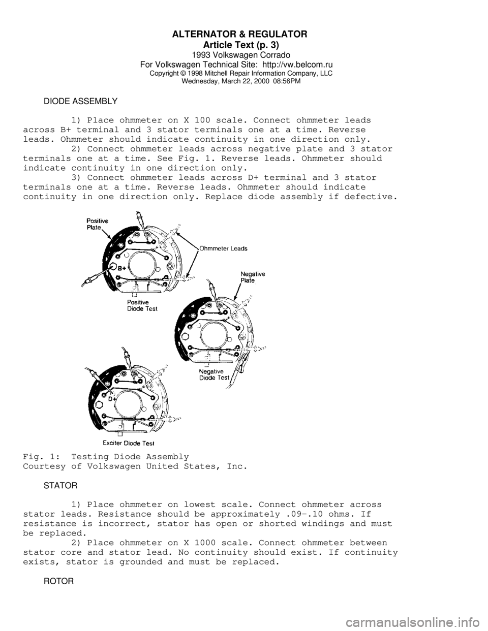
DIODE ASSEMBLY
1) Place ohmmeter on X 100 scale. Connect ohmmeter leads
across B+ terminal and 3 stator terminals one at a time. Reverse
leads. Ohmmeter should indicate continuity in one direction only.
2) Connect ohmmeter leads across negative plate and 3 stator
terminals one at a time. See Fig. 1. Reverse leads. Ohmmeter should
indicate continuity in one direction only.
3) Connect ohmmeter leads across D+ terminal and 3 stator
terminals one at a time. Reverse leads. Ohmmeter should indicate
continuity in one direction only. Replace diode assembly if defective.Fig. 1: Testing Diode Assembly
Courtesy of Volkswagen United States, Inc.
STATOR
1) Place ohmmeter on lowest scale. Connect ohmmeter across
stator leads. Resistance should be approximately .09-.10 ohms. If
resistance is incorrect, stator has open or shorted windings and must
be replaced.
2) Place ohmmeter on X 1000 scale. Connect ohmmeter between
stator core and stator lead. No continuity should exist. If continuity
exists, stator is grounded and must be replaced.
ROTOR
Page 408 of 920

ALTERNATOR & REGULATOR
Article Text (p. 4)
1993 Volkswagen Corrado
For Volkswagen Technical Site: http://vw.belcom.ru
Copyright © 1998 Mitchell Repair Information Company, LLC
Wednesday, March 22, 2000 08:56PM
1) Place ohmmeter on lowest scale. Connect ohmmeter across
slip rings. Resistance should be 2.8-3.1 ohms.
2) If resistance is too low, rotor has short circuit and must
be replaced. If resistance is infinity (no continuity), rotor has open
circuit and must be replaced.
3) Place ohmmeter on X 1000 scale. Connect ohmmeter between
either slip ring and rotor core. No continuity should exist. If
continuity exists, rotor is grounded and must be replaced.
4) Clean slip rings using fine sandpaper. Rings which are
worn or pitted should be turned on lathe. Minimum ring diameter is 1
1/16".
5) If slip rings are beyond repair, remove rear bearing from
slip ring end of rotor. Unsolder wires from slip rings and bend up
ends of rotor winding. Pull off slip rings. Ensure ends of rotor
winding are not damaged.
6) Insert ends of rotor winding into slip ring and press new
slip ring onto rotor. Slip ring end must be 9/64" from end of collar.
Solder rotor winding to slip ring terminals. Turn rings on lathe and
retest rotor. Maximum slip ring runout is .0012" (.03 mm).
BEARINGS
Always replace bearings. If replacement front bearing is
sealed on one side only, open side must face rotor. If replacement
rear bearing is sealed on one side only, open side must face away from
rotor.
BRUSHES
Ensure brushes are longer than 7/32". Replace if necessary.
Unsolder brushes from voltage regulator. Solder new brushes. DO NOT
allow solder to run into strands of brush leads. Brushes must be free
to slide in brush holder with normal spring tension of 10-14 ozs.
(283-397 g).
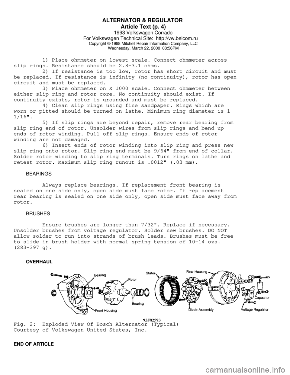
OVERHAULFig. 2: Exploded View Of Bosch Alternator (Typical)
Courtesy of Volkswagen United States, Inc.
END OF ARTICLE
Page 607 of 920

HOW TO USE SYSTEM WIRING DIAGRAMS
Article Text (p. 4)
1993 Volkswagen Corrado
For Volkswagen Technical Site: http://vw.belcom.ru
Copyright © 1998 Mitchell Repair Information Company, LLC
Wednesday, March 22, 2000 09:11PM
When trying to locate a component in a wiring diagram and you
don't know the specific system where it is located, use this handy
component locator to find the system wiring diagram in which the
component is located. Then, go to that system and locate the component
within the wiring diagram.
For example, if you don't know the specific system in which
the ignition switch is located, look up ignition switch in the wiring
diagram component location tables and go to the appropriate wiring
diagram(s) which contain either full or partial views of the ignition
switch. The full view of the ignition switch is located in Power
Distribution.
The first listing for the component will be the full or most
complete view of the component. Additional listings will be partial
views of the component. Not all components are used on all models.
All components will have a partial view in Ground
Distribution and Power Distribution. Data Link Connectors show
connecting circuits between modules. Alternate names for components
may be listed in wiring diagram component locations tables.
WIRING DIAGRAM COMPONENT LOCATIONS TABLEÄÄÄÄÄÄÄÄÄÄÄÄÄÄÄÄÄÄÄÄÄÄÄÄÄÄÄÄÄÄÄÄÄÄÄÄÄÄÄÄÄÄÄÄÄÄÄÄÄÄÄÄÄÄÄÄÄÄÄÄÄÄÄÄÄÄÄÄÄÄComponent Wiring Diagram
ABS Electronic Control Unit ....................... Anti-Lock Brakes
Data Link Connectors
ABS Hydraulic Unit ................................ Anti-Lock Brakes
Acceleration Sensor ............................... Anti-Lock Brakes
Accessory Delay Relay ................................ Power Windows
A/C Compressor Clutch Relay ..................... Engine Performance
A/C Sensor ...................................... Engine Performance
A/C Pressure Switch ............................. Engine Performance
Adaptive Lamp Control Module ....................... Exterior Lights
Air Bag(s) ................................ Air Bag Restraint System
Air Bag Module ............................ Air Bag Restraint System
Air Bag Sensor(s) ......................... Air Bag Restraint System
Air Injection Pump Relay ........................ Engine Performance
Air Temperature Sensor ............................ Overhead Console
Alternator (Generator) ..................... Generators & Regulators
Anti-Theft Control Module ........................ Anti-Theft System
Starters
Autolamp Control Relay ........................... Headlight Systems
Daytime Running Lights
Automatic Shutdown (ASD) Relay .................. Engine Performance
Generators & Regulators
Autostick Switch ................................ Engine Performance
Auxiliary Battery Relay .................... Generators & Regulators
Back-Up Lights ...................................... Back-Up Lights
Exterior Lights
Barometric (BARO) Pressure Sensor ............... Engine Performance
Battery ......................................... Power Distribution
Battery Temperature Sensor ...................... Engine Performance