1993 VOLKSWAGEN CORRADO oil pressure
[x] Cancel search: oil pressurePage 6 of 920

* A/C-HEATER SYSTEM UNIFORM INSPECTION GUIDELINES *
Article Text (p. 4)
1993 Volkswagen Corrado
For Volkswagen Technical Site: http://vw.belcom.ru
Copyright © 1998 Mitchell Repair Information Company, LLC
Wednesday, March 22, 2000 08:21PM
³ required. ³ state of charge following
³ ³ manufacturer's recommended
³ ³ service procedures. If the
³ ³ compressor is still noisy,
³ ³ suggest repair or
³ ³ replacement. Compressor may
³ ³ be near the end of its
³ ³ useful life.
ÄÄÄÄÄÄÄÄÄÄÄÄÄÄÄÄÄÄÅÄÄÄÄÄÄÄÄÄÄÄÄÄÄÄÄÄÄÄÄÄÄÅÄÄÄÄÄÄÄÄÄÄÄÄÄÄÄÄÄÄÄÄÄÄÄÄÄÄÄÄDamaged housing
³ Suggest repair or ³ If damage affects proper
³ replacement. ³ operation of system require
³ ³ replacement.
ÄÄÄÄÄÄÄÄÄÄÄÄÄÄÄÄÄÄÅÄÄÄÄÄÄÄÄÄÄÄÄÄÄÄÄÄÄÄÄÄÄÅÄÄÄÄÄÄÄÄÄÄÄÄÄÄÄÄÄÄÄÄÄÄÄÄÄÄÄÄLeaks
³ Require repair or ³
³ replacement. ³
ÄÄÄÄÄÄÄÄÄÄÄÄÄÄÄÄÄÄÅÄÄÄÄÄÄÄÄÄÄÄÄÄÄÄÄÄÄÄÄÄÄÅÄÄÄÄÄÄÄÄÄÄÄÄÄÄÄÄÄÄÄÄÄÄÄÄÄÄÄÄMissing or
³ Require repair or ³damaged mounting
³ replacement. ³brackets/hardware
³ ³
ÄÄÄÄÄÄÄÄÄÄÄÄÄÄÄÄÄÄÁÄÄÄÄÄÄÄÄÄÄÄÄÄÄÄÄÄÄÄÄÄÄÁÄÄÄÄÄÄÄÄÄÄÄÄÄÄÄÄÄÄÄÄÄÄÄÄÄÄÄÄCLUTCH ASSEMBLY
ÄÄÄÄÄÄÄÄÄÄÄÄÄÄÄÄÄÄÂÄÄÄÄÄÄÄÄÄÄÄÄÄÄÄÄÄÄÄÄÄÄÂÄÄÄÄÄÄÄÄÄÄÄÄÄÄÄÄÄÄÄÄÄÄÄÄÄÄÄÄCondition
³ Procedure ³ Note
ÄÄÄÄÄÄÄÄÄÄÄÄÄÄÄÄÄÄÅÄÄÄÄÄÄÄÄÄÄÄÄÄÄÄÄÄÄÄÄÄÄÅÄÄÄÄÄÄÄÄÄÄÄÄÄÄÄÄÄÄÄÄÄÄÄÄÄÄÄÄInoperative/slips
³ Further inspection ³ Check air gap, belt
³ required. ³ tension, system pressure,
³ ³ electrical system. Require
³ ³ repair or replacement
³ ³ according to manufacturer's
³ ³ specifications.
ÄÄÄÄÄÄÄÄÄÄÄÄÄÄÄÄÄÄÅÄÄÄÄÄÄÄÄÄÄÄÄÄÄÄÄÄÄÄÄÄÄÅÄÄÄÄÄÄÄÄÄÄÄÄÄÄÄÄÄÄÄÄÄÄÄÄÄÄÄÄNoisy
³ Suggest repair or ³
³ replacement. ³
ÄÄÄÄÄÄÄÄÄÄÄÄÄÄÄÄÄÄÅÄÄÄÄÄÄÄÄÄÄÄÄÄÄÄÄÄÄÄÄÄÄÅÄÄÄÄÄÄÄÄÄÄÄÄÄÄÄÄÄÄÄÄÄÄÄÄÄÄÄÄSeized bearing
³ Require replacement ³
³ of bearing. ³
ÄÄÄÄÄÄÄÄÄÄÄÄÄÄÄÄÄÄÅÄÄÄÄÄÄÄÄÄÄÄÄÄÄÄÄÄÄÄÄÄÄÅÄÄÄÄÄÄÄÄÄÄÄÄÄÄÄÄÄÄÄÄÄÄÄÄÄÄÄÄBurnt coil
³ Require replacement ³
³ of coil. ³
ÄÄÄÄÄÄÄÄÄÄÄÄÄÄÄÄÄÄÅÄÄÄÄÄÄÄÄÄÄÄÄÄÄÄÄÄÄÄÄÄÄÅÄÄÄÄÄÄÄÄÄÄÄÄÄÄÄÄÄÄÄÄÄÄÄÄÄÄÄÄDamaged connector
³ Require repair or ³
³ replacement. ³
ÄÄÄÄÄÄÄÄÄÄÄÄÄÄÄÄÄÄÅÄÄÄÄÄÄÄÄÄÄÄÄÄÄÄÄÄÄÄÄÄÄÅÄÄÄÄÄÄÄÄÄÄÄÄÄÄÄÄÄÄÄÄÄÄÄÄÄÄÄÄDamaged hub
³ Require repair or ³
³ replacement of hub. ³
ÄÄÄÄÄÄÄÄÄÄÄÄÄÄÄÄÄÄÅÄÄÄÄÄÄÄÄÄÄÄÄÄÄÄÄÄÄÄÄÄÄÅÄÄÄÄÄÄÄÄÄÄÄÄÄÄÄÄÄÄÄÄÄÄÄÄÄÄÄÄWill not disengage
³ Further inspection ³ Check air gap & electrical
³ required. ³ system. Suggest repair or
³ ³ replacement.
ÄÄÄÄÄÄÄÄÄÄÄÄÄÄÄÄÄÄÁÄÄÄÄÄÄÄÄÄÄÄÄÄÄÄÄÄÄÄÄÄÄÁÄÄÄÄÄÄÄÄÄÄÄÄÄÄÄÄÄÄÄÄÄÄÄÄÄÄÄÄ
Page 102 of 920

* ENGINE SYSTEMS UNIFORM INSPECTION GUIDELINES *
Article Text (p. 5)
1993 Volkswagen Corrado
For Volkswagen Technical Site: http://vw.belcom.ru
Copyright © 1998 Mitchell Repair Information Company, LLC
Wednesday, March 22, 2000 08:40PM
threads in oil pan for damage.ÄÄÄÄÄÄÄÄÄÄÄÄÄÄÄÄÄÄÄÄÄÄÄÄÄÄÄÄÄÄÄÄÄÄÄÄÄÄÄÄÄÄÄÄÄÄÄÄÄÄÄÄÄÄÄÄÄÄÄÄÄÄÄÄÄÄÄÄÄÄENGINE OIL WARNING LIGHTS
ÄÄÄÄÄÄÄÄÄÄÄÄÄÄÄÄÄÄÄÄÄÄÄÄÄÄÄÄÄÄÄÂÄÄÄÄÄÄÄÄÄÄÄÄÄÄÄÄÄÄÄÄÄÄÄÄÄÄÄÄÄÄÄÄÄÄÄÄÄÄCondition
³ Procedure
ÄÄÄÄÄÄÄÄÄÄÄÄÄÄÄÄÄÄÄÄÄÄÄÄÄÄÄÄÄÄÄÅÄÄÄÄÄÄÄÄÄÄÄÄÄÄÄÄÄÄÄÄÄÄÄÄÄÄÄÄÄÄÄÄÄÄÄÄÄÄLight not on during bulb check
³ Further inspection required. See
³ NOTE: below.
ÄÄÄÄÄÄÄÄÄÄÄÄÄÄÄÄÄÄÄÄÄÄÄÄÄÄÄÄÄÄÄÅÄÄÄÄÄÄÄÄÄÄÄÄÄÄÄÄÄÄÄÄÄÄÄÄÄÄÄÄÄÄÄÄÄÄÄÄÄÄLight stays on or intermittent
³ Further inspection required. See
while engine is running
³ NOTE: below.
ÄÄÄÄÄÄÄÄÄÄÄÄÄÄÄÄÄÄÄÄÄÄÄÄÄÄÄÄÄÄÄÅÄÄÄÄÄÄÄÄÄÄÄÄÄÄÄÄÄÄÄÄÄÄÄÄÄÄÄÄÄÄÄÄÄÄÄÄÄÄNOTE: Light may indicate problem with contaminated oil, level,
pressure, temperature or problem with circuit.
ÄÄÄÄÄÄÄÄÄÄÄÄÄÄÄÄÄÄÄÄÄÄÄÄÄÄÄÄÄÄÄÄÄÄÄÄÄÄÄÄÄÄÄÄÄÄÄÄÄÄÄÄÄÄÄÄÄÄÄÄÄÄÄÄÄÄÄÄÄÄENGINE OIL PRESSURE GAUGE
ÄÄÄÄÄÄÄÄÄÄÄÄÄÄÄÄÄÄÄÄÄÄÄÂÄÄÄÄÄÄÄÄÄÄÄÄÄÄÄÄÄÄÄÄÄÄÄÄÄÄÄÄÄÄÄÄÄÄÄÄÄÄÄÄÄÄÄÄÄÄCondition
³ Procedure
ÄÄÄÄÄÄÄÄÄÄÄÄÄÄÄÄÄÄÄÄÄÄÄÅÄÄÄÄÄÄÄÄÄÄÄÄÄÄÄÄÄÄÄÄÄÄÄÄÄÄÄÄÄÄÄÄÄÄÄÄÄÄÄÄÄÄÄÄÄÄInoperative
³ Further inspection required. See note.
ÄÄÄÄÄÄÄÄÄÄÄÄÄÄÄÄÄÄÄÄÄÄÄÅÄÄÄÄÄÄÄÄÄÄÄÄÄÄÄÄÄÄÄÄÄÄÄÄÄÄÄÄÄÄÄÄÄÄÄÄÄÄÄÄÄÄÄÄÄÄIndicates out of range
³ Further inspection required. See note.
ÄÄÄÄÄÄÄÄÄÄÄÄÄÄÄÄÄÄÄÄÄÄÄÁÄÄÄÄÄÄÄÄÄÄÄÄÄÄÄÄÄÄÄÄÄÄÄÄÄÄÄÄÄÄÄÄÄÄÄÄÄÄÄÄÄÄÄÄÄÄNOTE: Gauge may indicate problem with contaminated oil, level,
pressure, temperature or problem with gauge.
ÄÄÄÄÄÄÄÄÄÄÄÄÄÄÄÄÄÄÄÄÄÄÄÄÄÄÄÄÄÄÄÄÄÄÄÄÄÄÄÄÄÄÄÄÄÄÄÄÄÄÄÄÄÄÄÄÄÄÄÄÄÄÄÄÄÄÄÄÄÄOIL PRESSURE SENDING UNIT
ÄÄÄÄÄÄÄÄÄÄÄÄÄÄÄÄÄÄÄÄÄÄÄÄÄÄÄÄÄÄÄÄÄÄÄÄÂÄÄÄÄÄÄÄÄÄÄÄÄÄÄÄÄÄÄÄÄÄÄÄÄÄÄÄÄÄÄÄÄÄCondition
³ Procedure
ÄÄÄÄÄÄÄÄÄÄÄÄÄÄÄÄÄÄÄÄÄÄÄÄÄÄÄÄÄÄÄÄÄÄÄÄÅÄÄÄÄÄÄÄÄÄÄÄÄÄÄÄÄÄÄÄÄÄÄÄÄÄÄÄÄÄÄÄÄÄLeaking
³ Require replacement.
ÄÄÄÄÄÄÄÄÄÄÄÄÄÄÄÄÄÄÄÄÄÄÄÄÄÄÄÄÄÄÄÄÄÄÄÄÅÄÄÄÄÄÄÄÄÄÄÄÄÄÄÄÄÄÄÄÄÄÄÄÄÄÄÄÄÄÄÄÄÄConnector or terminal bent, broken,
³ Require repair or replacement.
or loose
³
ÄÄÄÄÄÄÄÄÄÄÄÄÄÄÄÄÄÄÄÄÄÄÄÄÄÄÄÄÄÄÄÄÄÄÄÄÅÄÄÄÄÄÄÄÄÄÄÄÄÄÄÄÄÄÄÄÄÄÄÄÄÄÄÄÄÄÄÄÄÄInoperative/inaccurate
³ Require repair or replacement.
ÄÄÄÄÄÄÄÄÄÄÄÄÄÄÄÄÄÄÄÄÄÄÄÄÄÄÄÄÄÄÄÄÄÄÄÄÁÄÄÄÄÄÄÄÄÄÄÄÄÄÄÄÄÄÄÄÄÄÄÄÄÄÄÄÄÄÄÄÄÄPOWER STEERING FLUID
ÄÄÄÄÄÄÄÄÄÄÄÄÄÄÄÄÄÄÄÄÄÄÂÄÄÄÄÄÄÄÄÄÄÄÄÄÄÄÄÄÄÄÄÄÄÄÄÄÄÄÄÄÄÄÄÄÄÄÄÄÄÄÄÄÄÄÄÄÄÄCondition
³ Procedure
ÄÄÄÄÄÄÄÄÄÄÄÄÄÄÄÄÄÄÄÄÄÄÁÄÄÄÄÄÄÄÄÄÄÄÄÄÄÄÄÄÄÄÄÄÄÄÄÄÄÄÄÄÄÄÄÄÄÄÄÄÄÄÄÄÄÄÄÄÄÄSee Steering and Suspension Uniform Inspection Guidelines
ÄÄÄÄÄÄÄÄÄÄÄÄÄÄÄÄÄÄÄÄÄÄÄÄÄÄÄÄÄÄÄÄÄÄÄÄÄÄÄÄÄÄÄÄÄÄÄÄÄÄÄÄÄÄÄÄÄÄÄÄÄÄÄÄÄÄÄÄÄÄTIMING BELT
ÄÄÄÄÄÄÄÄÄÄÄÄÄÄÄÄÄÄÄÄÄÄÂÄÄÄÄÄÄÄÄÄÄÄÄÄÄÄÄÄÄÄÄÄÄÄÄÄÄÄÄÄÄÄÄÄÄÄÄÄÄÄÄÄÄÄÄÄÄÄCondition
³ Procedure
ÄÄÄÄÄÄÄÄÄÄÄÄÄÄÄÄÄÄÄÄÄÄÅÄÄÄÄÄÄÄÄÄÄÄÄÄÄÄÄÄÄÄÄÄÄÄÄÄÄÄÄÄÄÄÄÄÄÄÄÄÄÄÄÄÄÄÄÄÄÄ
Page 302 of 920

2.8L IN-LINE V6 (VR6)
Article Text (p. 11)
1993 Volkswagen Corrado
For Volkswagen Technical Site: http://vw.belcom.ru
Copyright © 1998 Mitchell Repair Information Company, LLC
Wednesday, March 22, 2000 08:47PM
Cylinder Head
Clean all gasket mating surfaces. Check cylinder head for
warpage. Ensure warpage does not exceed .004" (0.1 mm).
Valve Stem Oil Seals
With valve springs removed, remove oil seals using Valve Seal
Remover (3047A). To install new oil seal, slide plastic sleeve over
valve stem. Lubricate new oil seal. Using Valve Seal Installer (3129),
push oil seal on valve guide.
Valve Guides
1) Check valve-to-guide clearance specification. See
CYLINDER HEAD table under ENGINE SPECIFICATIONS at end of article. If
valve guide have previously been replaced, replace cylinder head.
2) To replace valve guide, press guide out from camshaft
side. Lubricate guide and press in cold cylinder head (from camshaft
side) until shoulder makes contact. DO NOT exceed one ton pressure.
Ream guides to proper valve-to-guide clearance. See CYLINDER HEAD
table under ENGINE SPECIFICATIONS at end of article.
Valve Seats
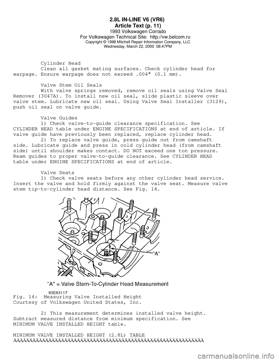
1) Check valve seats before any other cylinder head service.
Insert the valve and hold firmly against the valve seat. Measure valve
stem tip-to-cylinder head distance. See Fig. 14.Fig. 14: Measuring Valve Installed Height
Courtesy of Volkswagen United States, Inc.
2) This measurement determines installed valve height.
Subtract measured distance from minimum specification. See
MINIMUM VALVE INSTALLED HEIGHT table.
MINIMUM VALVE INSTALLED HEIGHT (2.8L) TABLEÄÄÄÄÄÄÄÄÄÄÄÄÄÄÄÄÄÄÄÄÄÄÄÄÄÄÄÄÄÄÄÄÄÄÄÄÄÄÄÄÄÄÄÄÄÄÄÄÄÄÄÄÄÄÄÄÄÄÄÄ
Page 306 of 920

2.8L IN-LINE V6 (VR6)
Article Text (p. 15)
1993 Volkswagen Corrado
For Volkswagen Technical Site: http://vw.belcom.ru
Copyright © 1998 Mitchell Repair Information Company, LLC
Wednesday, March 22, 2000 08:47PM
ENGINE OILING
ENGINE LUBRICATION SYSTEM
Crankcase Capacity
See CRANKCASE CAPACITY table.
CRANKCASE CAPACITY TABLEÄÄÄÄÄÄÄÄÄÄÄÄÄÄÄÄÄÄÄÄÄÄÄÄÄÄÄÄÄÄÄÄÄÄÄÄÄÄÄÄÄÄÄÄÄÄÄÄÄÄÄÄÄÄÄÄÄÄÄÄ With Filter Without Filter
Model Replacement Replacement
2.8L ............. 6.3 Qts. (6.0L) ..... 5.3 Qts. (5.0L)
ÄÄÄÄÄÄÄÄÄÄÄÄÄÄÄÄÄÄÄÄÄÄÄÄÄÄÄÄÄÄÄÄÄÄÄÄÄÄÄÄÄÄÄÄÄÄÄÄÄÄÄÄÄÄÄÄÄÄÄÄ Oil Pressure
Check oil pressure with engine at warm operating temperature.
Minimum oil pressure at 2000 RPM is 29 psi (2.0 kg/cm
ý). If oil
pressure is incorrect, check oil pump and oil pressure relief valve.
OIL PUMP
Removal & Installation
Remove oil pan. Remove oil pump attaching bolts and remove
oil pump assembly. To install, reverse removal procedure.
Inspection
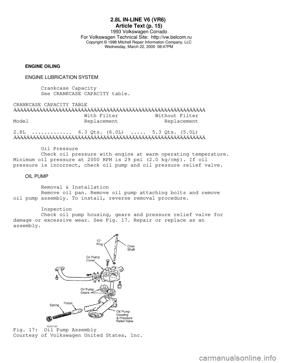
Check oil pump housing, gears and pressure relief valve for
damage or excessive wear. See Fig. 17. Repair or replace as an
assembly.Fig. 17: Oil Pump Assembly
Courtesy of Volkswagen United States, Inc.
Page 307 of 920

2.8L IN-LINE V6 (VR6)
Article Text (p. 16)
1993 Volkswagen Corrado
For Volkswagen Technical Site: http://vw.belcom.ru
Copyright © 1998 Mitchell Repair Information Company, LLC
Wednesday, March 22, 2000 08:47PM
TORQUE SPECIFICATIONS
TORQUE SPECIFICATIONS TABLEÄÄÄÄÄÄÄÄÄÄÄÄÄÄÄÄÄÄÄÄÄÄÄÄÄÄÄÄÄÄÄÄÄÄÄÄÄÄÄÄÄÄÄÄÄÄÄÄÄÄÄÄÄÄÄÄÄÄÄÄApplication Ft. Lbs. (N.m)
A/C Bracket-To-Engine Bolt ....................... 22 (30)
Axle Shaft-To-Transaxle Drive Flange Bolt ........ 33 (45)
Camshaft Bearing Cap Bolt ........................ 15 (20)
Camshaft Sprocket Bolt .......................... 74 (100)
Clutch Cover Bolt ................................ 15 (20)
Connecting Rod Bolt ................... 22 (30) + 1/4 Turn
Crankshaft Main Bearing Cap Bolt ...... 22 (30) + 1/2 Turn
Cylinder Head Bolt (1)
Step 1 ......................................... 30 (40)
Step 2 ......................................... 44 (60)
Step 3 ....................... Additional 1/4 (90
ø) Turn
Step 4 ....................... Additional 1/4 (90
ø) Turn
Engine Bracket (Front) ........................... 44 (60)
Engine Bracket (To Body) ......................... 33 (45)
Engine-To-Transaxle 10-mm Bolt ................... 44 (60)
Engine-To-Transaxle 12-mm Bolt ................... 55 (80)
Exhaust Manifold-To-Cylinder Head Bolt & Nut ..... 18 (25)
Exhaust Pipe-To-Catalytic Converter Bolt ......... 18 (25)
Exhaust Pipe-To-Manifold Nut ..................... 30 (40)
Flywheel-To-Crankshaft Bolt ........... 44 (60) + 1/4 Turn
Intake Manifold .................................. 18 (25)
Intermediate Shaft Sprocket Bolt ................ 74 (100)
Oil Pan Bolt ..................................... 15 (20)
Oil Pan Drain Plug ............................... 37 (50)
Oil Pressure Switch .............................. 18 (25)
Oil Pump Cover Long Bolt ............................. (2)
Oil Pump Cover Short Bolt ........................ 18 (25)
Power Steering Pump Bracket Bolt ................. 18 (25)
Pressure Plate Bolt .............................. 15 (20)
Starter Mount Bolt ............................... 18 (25)
Timing Belt Tensioner Nut ........................ 15 (20)
Torque Converter-To-Carrier Plate Bolt ........... 22 (30)
Vibration Damper Bolt .......................... 332 (450)
Water Pump Pulley Bolt ........................... 15 (20)
Water Pump Housing-To-Engine Bolt ................ 15 (20)
INCH Lbs. (N.m)
Fuel Rail Bolt (Lower) ............................ 89 (10)
Timing Belt Idler Bolt ........................... 89 (10)
Valve Cover Retaining Nut ........................ 89 (10)
Water Pump-To-Housing ........................... 115 (13)
(1) - Never reuse cylinder head bolt(s) when servicing.
(2) - Tighten bolt to 89 INCH lbs. (10 N.m).
ÄÄÄÄÄÄÄÄÄÄÄÄÄÄÄÄÄÄÄÄÄÄÄÄÄÄÄÄÄÄÄÄÄÄÄÄÄÄÄÄÄÄÄÄÄÄÄÄÄÄÄÄÄÄÄÄÄÄÄÄ
Page 331 of 920

A/C COMPRESSOR OIL CHECKING
Article Text (p. 17)
1993 Volkswagen Corrado
For Volkswagen Technical Site: http://vw.belcom.ru
Copyright © 1998 Mitchell Repair Information Company, LLC
Wednesday, March 22, 2000 08:47PM
Add 2/3 ounce of refrigerant oil when replacing condenser.
Add 1 1/3 ounces when replacing evaporator. When replacing receiver-
drier or hoses, add 1/3 ounce per component replaced. If A/C system
line has broken (sudden discharge), add1 1/3 ounces of refrigerant
oil.
NOTE: On Mercedes-Benz vehicles with rear A/C, add 2/3 ounce of
refrigerant oil when replacing rear condenser. When
replacing rear A/C lines, add 1/3 ounce per line replaced.
Mitsubishi
1) On Eclipse, add 2/3 ounce of refrigerant oil when
replacing condenser. Add one ounce when replacing evaporator. When
replacing receiver-drier or hoses, add 1/3 ounce per component
replaced.
2) On Expo/Expo LRV and Montero, add one ounce of refrigerant
oil when replacing condenser. Add 2 ounces when replacing evaporator.
When replacing receiver-drier or hoses, add 1/3 ounce per component
replaced.
Volkswagen (Fox)
1) The use of refrigerant recovery/recycling is recommended
by manufacturer. After refrigerant recovery process is completed, the
amount of compressor oil removed must be measured and the same amount
added to A/C system.
2) Add 1 1/2 ounce of refrigerant oil when replacing
evaporator. When replacing condenser, add 1 1/3 ounce of refrigerant
oil. Add one ounce of refrigerant oil when replacing receiver-drier (1
1/2 ounces if relief valve on receiver-drier has burst).
PANASONIC
ROTARY VANE
Mazda
Add 1 1/3 ounce of refrigerant oil when replacing condenser
(1/2 ounce on MX-6 and 626). Add 2 ounces when replacing evaporator.
When replacing receiver-drier or hoses, add 1/3 ounce of refrigerant
oil.
SANDEN
SCROLL
Chrysler/Mitsubishi
1) On Colt, Galant, Mirage, Pickup, Ram-50 and Summit, add
1/2 ounce of refrigerant oil when replacing condenser. Add 1 1/2
ounces when replacing evaporator. When replacing receiver-drier or
hoses, add 1/3 ounce per component replaced.
2) On Stealth and 3000GT, add 1/2 ounce of refrigerant oil
when replacing condenser. Add 2 ounces when replacing evaporator. When
replacing receiver-drier or low-pressure hose, add 1/3 ounce per
Page 334 of 920

A/C COMPRESSOR OIL CHECKING
Article Text (p. 20)
1993 Volkswagen Corrado
For Volkswagen Technical Site: http://vw.belcom.ru
Copyright © 1998 Mitchell Repair Information Company, LLC
Wednesday, March 22, 2000 08:47PM
by manufacturer. After refrigerant recovery process is completed, the
amount of compressor oil removed must be measured and the same amount
added to A/C system.
2) On Cabriolet, add 2/3 ounce of refrigerant oil when
replacing evaporator. When replacing condenser or receiver-drier, add
1/3 ounce of refrigerant oil per component replaced.
3) On Corrado SLC, Golf, GTI, Jetta and Passat, add 2/3 ounce
of refrigerant oil when replacing evaporator. When replacing condenser
or receiver-drier, add 1/3 ounce of refrigerant oil per component
replaced.
4) On EuroVan, add one ounce of refrigerant oil when
replacing evaporator. Add 1/2 ounce when replacing condenser (2/3
ounce on vehicles with rear A/C). When replacing receiver-drier, add
1/3 ounce (2/3 ounce on vehicles with rear A/C).
SEIKO-SEIKI
ROTARY VANE
Saab (9000)
The A/C system is filled with 6.6 ounces of compressor oil.
The compressor must be topped off with the specified amount. See
COMPONENT REFRIGERANT OIL CAPACITIES (SEIKO-SEIKI ROTARY VANE) table.
Topping off should be carried out on the high pressure side of the
compressor.
COMPONENT REFRIGERANT OIL CAPACITIES (SEIKO-SEIKI ROTARY VANE)ÄÄÄÄÄÄÄÄÄÄÄÄÄÄÄÄÄÄÄÄÄÄÄÄÄÄÄÄÄÄÄÄÄÄÄÄÄÄÄÄÄÄÄÄÄÄÄÄÄÄÄÄÄÄÄÄÄÄÄÄÄÄÄComponent Ounces
Compressor .......................................... (1) 2.3
Condenser ............................................... 1.3
Expansion Valve ......................................... 0.6
Evaporator .............................................. 1.3
Receiver-Drier .......................................... 1.3
Refrigerant Lines ....................................... 0.6
(1) - To avoid an excessive amount of oil in the A/C system, oil
must be drained from the compressor before it is installed.
ÄÄÄÄÄÄÄÄÄÄÄÄÄÄÄÄÄÄÄÄÄÄÄÄÄÄÄÄÄÄÄÄÄÄÄÄÄÄÄÄÄÄÄÄÄÄÄÄÄÄÄÄÄÄÄÄÄÄÄÄÄÄÄ ZEXEL
NOTE: Isuzu and Subaru compressor oil checking procedures are not
available from manufacturer.
ROTARY VANE
Nissan
1) Before checking and adjusting oil level, operate engine at
1200 RPM. Set controls at maximum cooling and high blower motor speed
for 10 minutes to return oil to compressor.
Page 343 of 920

A/C COMPRESSOR SERVICING
Article Text (p. 7)
1993 Volkswagen Corrado
For Volkswagen Technical Site: http://vw.belcom.ru
Copyright © 1998 Mitchell Repair Information Company, LLC
Wednesday, March 22, 2000 08:48PM
Removal
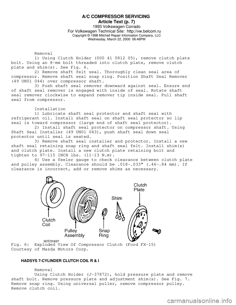
1) Using Clutch Holder (000 41 0812 05), remove clutch plate
bolt. Using an 8-mm bolt threaded into clutch plate, remove clutch
plate and shim(s). See Fig. 6.
2) Remove shaft felt seal. Thoroughly clean seal area of
compressor. Remove shaft seal snap ring. Position Shaft Seal Remover
(49 UN01 044) over compressor shaft.
3) Push shaft seal remover downward against seal. Ensure end
of shaft seal remover is engaged with inside of seal. Rotate shaft
seal remover clockwise to expand remover tip inside seal. Pull shaft
seal from compressor.
Installation
1) Lubricate shaft seal protector and shaft seal with
refrigerant oil. Install shaft seal on shaft seal protector so lip
seal is toward compressor (large end of shaft seal protector).
2) Install shaft seal protector on compressor shaft. Using
Shaft Seal Installer (49 UN01 043), push shaft seal down seal
protector until seal is seated.
3) Remove shaft seal installer and protector. Install a new
shaft seal retaining snap ring and shaft seal felt. Install shim(s)
and clutch plate. Install a new clutch plate retaining bolt and
tighten to 97-115 INCH lbs. (11-13 N.m).
4) Use a feeler gauge to check clearance between clutch plate
and pulley assembly. Clearance should be .018-.033" (.46-.84 mm). If
clearance is incorrect, add or remove shims as necessary.Fig. 6: Exploded View Of Compressor Clutch (Ford FX-15)
Courtesy of Mazda Motors Corp.
HADSYS 7-CYLINDER CLUTCH COIL R & I
Removal
Using Clutch Holder (J-37872), hold pressure plate and remove
shaft bolt. Remove pressure plate and adjustment shim(s). See Fig. 7.
Remove snap ring. Using universal puller, remove compressor pulley.
Remove clutch coil.