1993 VOLKSWAGEN CORRADO oil pressure
[x] Cancel search: oil pressurePage 344 of 920

A/C COMPRESSOR SERVICING
Article Text (p. 8)
1993 Volkswagen Corrado
For Volkswagen Technical Site: http://vw.belcom.ru
Copyright © 1998 Mitchell Repair Information Company, LLC
Wednesday, March 22, 2000 08:48PM
Installation
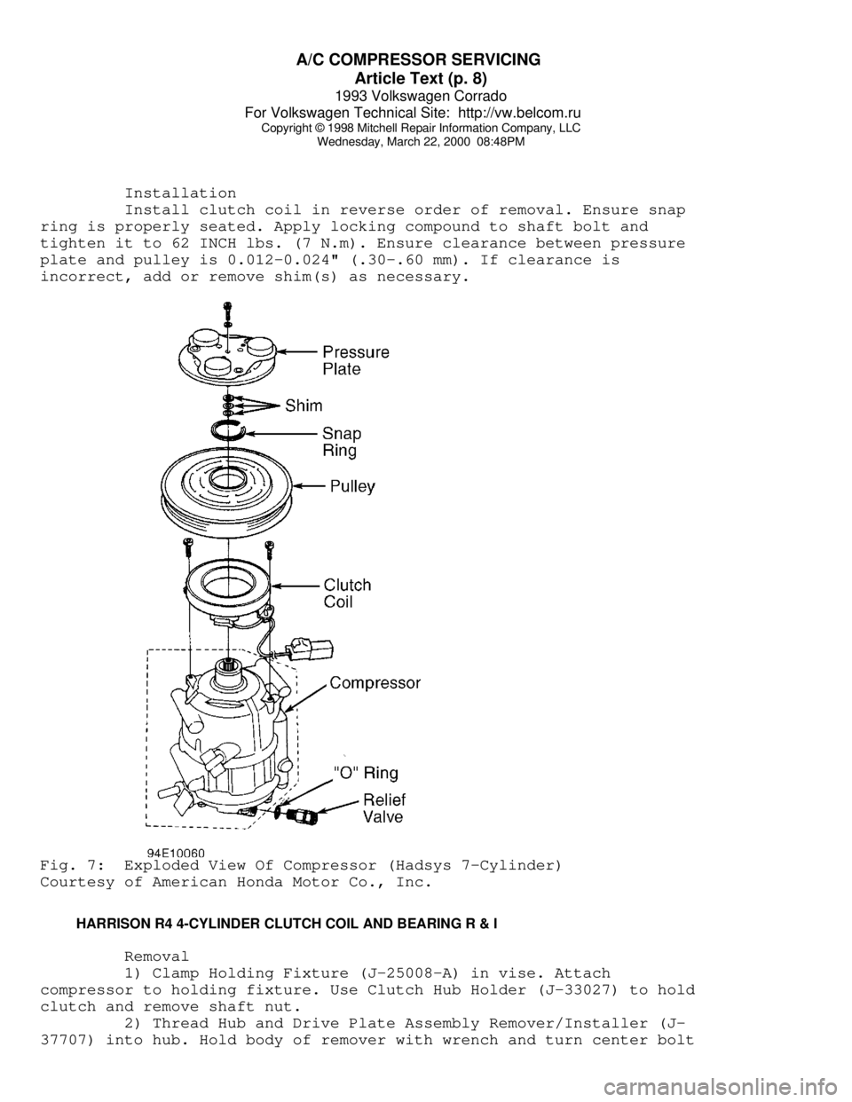
Install clutch coil in reverse order of removal. Ensure snap
ring is properly seated. Apply locking compound to shaft bolt and
tighten it to 62 INCH lbs. (7 N.m). Ensure clearance between pressure
plate and pulley is 0.012-0.024" (.30-.60 mm). If clearance is
incorrect, add or remove shim(s) as necessary.Fig. 7: Exploded View Of Compressor (Hadsys 7-Cylinder)
Courtesy of American Honda Motor Co., Inc.
HARRISON R4 4-CYLINDER CLUTCH COIL AND BEARING R & I
Removal
1) Clamp Holding Fixture (J-25008-A) in vise. Attach
compressor to holding fixture. Use Clutch Hub Holder (J-33027) to hold
clutch and remove shaft nut.
2) Thread Hub and Drive Plate Assembly Remover/Installer (J-
37707) into hub. Hold body of remover with wrench and turn center bolt
Page 347 of 920

A/C COMPRESSOR SERVICING
Article Text (p. 11)
1993 Volkswagen Corrado
For Volkswagen Technical Site: http://vw.belcom.ru
Copyright © 1998 Mitchell Repair Information Company, LLC
Wednesday, March 22, 2000 08:48PM
1) Coat new "O" ring with refrigerant oil and install on "O"
Ring Installer (J-33011). Install "O" ring into groove in compressor
neck. Attach new seal to seal remover/installer. Dip shaft seal in
clean refrigerant oil.
2) Place Seal Protector (J-34614) over compressor shaft. Push
new seal over shaft protector. Install new seal snap ring with flat
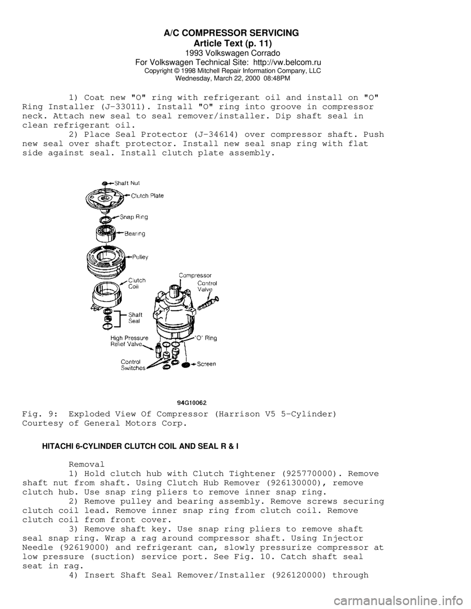
side against seal. Install clutch plate assembly.Fig. 9: Exploded View Of Compressor (Harrison V5 5-Cylinder)
Courtesy of General Motors Corp.
HITACHI 6-CYLINDER CLUTCH COIL AND SEAL R & I
Removal
1) Hold clutch hub with Clutch Tightener (925770000). Remove
shaft nut from shaft. Using Clutch Hub Remover (926130000), remove
clutch hub. Use snap ring pliers to remove inner snap ring.
2) Remove pulley and bearing assembly. Remove screws securing
clutch coil lead. Remove inner snap ring from clutch coil. Remove
clutch coil from front cover.
3) Remove shaft key. Use snap ring pliers to remove shaft
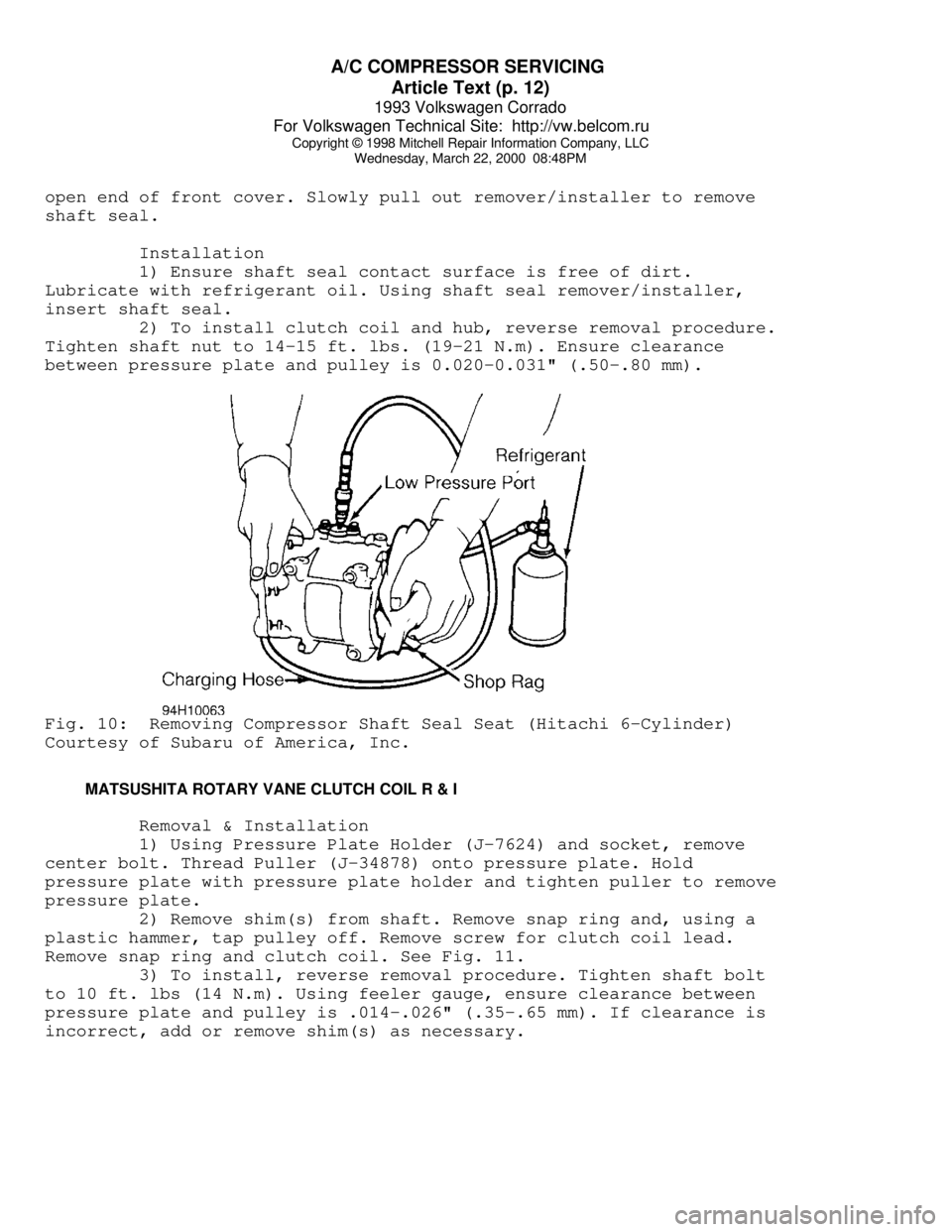
seal snap ring. Wrap a rag around compressor shaft. Using Injector
Needle (92619000) and refrigerant can, slowly pressurize compressor at
low pressure (suction) service port. See Fig. 10. Catch shaft seal
seat in rag.
4) Insert Shaft Seal Remover/Installer (926120000) through
Page 348 of 920

A/C COMPRESSOR SERVICING
Article Text (p. 12)
1993 Volkswagen Corrado
For Volkswagen Technical Site: http://vw.belcom.ru
Copyright © 1998 Mitchell Repair Information Company, LLC
Wednesday, March 22, 2000 08:48PM
open end of front cover. Slowly pull out remover/installer to remove
shaft seal.
Installation
1) Ensure shaft seal contact surface is free of dirt.
Lubricate with refrigerant oil. Using shaft seal remover/installer,
insert shaft seal.
2) To install clutch coil and hub, reverse removal procedure.
Tighten shaft nut to 14-15 ft. lbs. (19-21 N.m). Ensure clearance
between pressure plate and pulley is 0.020-0.031" (.50-.80 mm).Fig. 10: Removing Compressor Shaft Seal Seat (Hitachi 6-Cylinder)
Courtesy of Subaru of America, Inc.
MATSUSHITA ROTARY VANE CLUTCH COIL R & I
Removal & Installation
1) Using Pressure Plate Holder (J-7624) and socket, remove
center bolt. Thread Puller (J-34878) onto pressure plate. Hold
pressure plate with pressure plate holder and tighten puller to remove
pressure plate.
2) Remove shim(s) from shaft. Remove snap ring and, using a
plastic hammer, tap pulley off. Remove screw for clutch coil lead.
Remove snap ring and clutch coil. See Fig. 11.
3) To install, reverse removal procedure. Tighten shaft bolt
to 10 ft. lbs (14 N.m). Using feeler gauge, ensure clearance between
pressure plate and pulley is .014-.026" (.35-.65 mm). If clearance is
incorrect, add or remove shim(s) as necessary.
Page 354 of 920

A/C COMPRESSOR SERVICING
Article Text (p. 18)
1993 Volkswagen Corrado
For Volkswagen Technical Site: http://vw.belcom.ru
Copyright © 1998 Mitchell Repair Information Company, LLC
Wednesday, March 22, 2000 08:48PM
using Pliers (MB991367) and Bolts (MB991386). Use a ratchet and socket
to remove clutch hub nut.
2) Remove clutch plate. Remove snap ring with internal snap
ring pliers. Remove clutch hub (rotor). Remove snap ring and clutch
coil.
3) Using an awl, remove bearing cover and retainer. Using
Bearing Remover (MB991456), engage bearing grooves. Place base of
bearing remover over remover arms and tighten nut.
4) Tighten bearing remover bolt to withdraw bearing from
compressor. Engage grooves of Shaft Seal Remover/Installer (MB991458)
and pull straight up on shaft seal.
Installation (Chrysler & Mitsubishi Except Galant & Mirage)
1) To install shaft seal, ensure front housing is free of
foreign objects. Lubricate Shaft Seal Protector (MB991459) and place
over compressor shaft. Lubricate shaft seal and install using shaft
seal remover/installer. Remove shaft seal protector.
2) Using a 21 mm socket or Drift (MB991301), carefully press
bearing onto compressor shaft. Install clutch coil so that alignment
pin is engaged. Install clutch coil snap ring with tapered side facing
out.
3) Align armature plate with crankshaft spline. Tighten shaft
nut to 12 ft. lbs (16 N.m). Using feeler gauge, ensure clearance
between pressure plate and pulley is .016-.024" (.40-0.60 mm). If
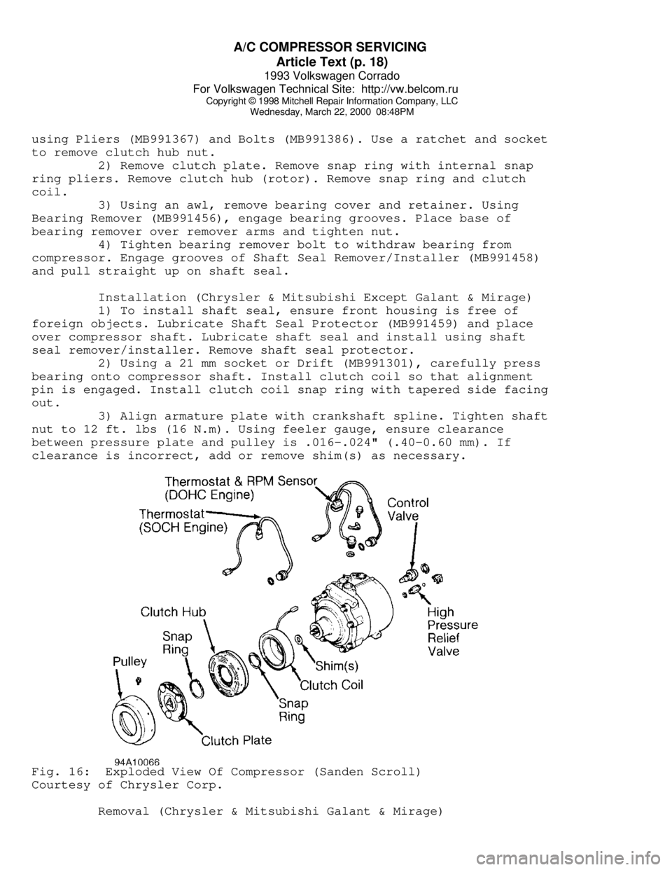
clearance is incorrect, add or remove shim(s) as necessary.Fig. 16: Exploded View Of Compressor (Sanden Scroll)
Courtesy of Chrysler Corp.
Removal (Chrysler & Mitsubishi Galant & Mirage)
Page 356 of 920

A/C COMPRESSOR SERVICING
Article Text (p. 20)
1993 Volkswagen Corrado
For Volkswagen Technical Site: http://vw.belcom.ru
Copyright © 1998 Mitchell Repair Information Company, LLC
Wednesday, March 22, 2000 08:48PM
Removal & Installation (Honda & Hyundai)
1) Remove shaft nut while holding clutch plate with Armature
Holder (J-37872). Using Puller (07935-8050003), remove pressure plate
and shim(s). See Fig. 16. Remove snap ring.
2) Place Seal Driver (07945-4150200) in center of pulley.
Engage universal puller to outer diameter of pulley. DO NOT engage
puller on belt area. Hold puller in place and tighten screw to remove
pulley. Remove screw for clutch coil lead. Remove snap ring and clutch
coil.
3) To install clutch coil, reverse removal procedure. Align
lug on clutch coil with hole in compressor. Install snap rings with
chamfered side facing out. Tighten shaft nut to 12-14 ft. lbs. (16-19
N.m). Using feeler gauge, ensure clearance between pressure plate and
pulley is .014-.026" (.35-.65 mm). If clearance is incorrect, add or
remove shim(s) as necessary.
NOTE: Shaft seal removal and installation procedures not available
from Honda or Hyundai.
SANDEN 5-CYLINDER CLUTCH COIL R & I
Removal
1) Hold clutch plate, using Holder (0000-41-0809-01), and
remove shaft nut. Remove clutch plate using Puller (0000-41-0809-02).
Remove shaft key and shim(s). Remove external front housing snap ring
and internal bearing snap ring (if used).
2) Install Clutch Pilot (0000-41-0810-77), Pulley/Clutch
Remover (0000-41-0810-76), and Puller (0000-41-0804-51/57) to remove
pulley assembly. Remove snap ring and drive bearing out of pulley.
Remove screw for clutch coil lead. Remove snap ring and clutch coil.
Installation
1) Install new bearing, ensuring Bearing Installer (000-41-
0804-43) contacts outer race of bearing. Install snap ring and ensure
bearing turns freely.
2) Install clutch coil, ensuring lug on coil aligns with hole
in front housing. Support compressor on rear mounting ears. Align
rotor on front housing hub. Use bearing installer and Driver (0000-41-
0810-59) to install pulley. With pulley seated, install snap ring(s).
Install shim(s) and shaft key.
3) Place clutch plate over shaft and, using Shaft Protector
(0000-41-0809-10), tap clutch plate into place. Install and tighten
shaft nut to 25-32 ft. lbs. (34-44 N.m). Using feeler gauge, ensure
clearance between clutch plate and pulley is .016-.032" (.40-.80 mm).
If clearance is incorrect, add or remove shim(s) as necessary.
SANDEN 5-CYLINDER CYLINDER HEAD & VALVE PLATE R & I
Removal & Installation
Remove compressor cylinder head (rear cover) bolts. Carefully
pry cylinder head of compressor. Remove reed valve plate and gasket.
To install components, reverse removal procedure. Tighten compressor
Page 363 of 920

A/C SYSTEM GENERAL DIAGNOSTIC PROCEDURES
Article Text
1993 Volkswagen Corrado
For Volkswagen Technical Site: http://vw.belcom.ru
Copyright © 1998 Mitchell Repair Information Company, LLC
Wednesday, March 22, 2000 08:48PM
ARTICLE BEGINNING
1993 AIR CONDITIONING & HEAT
A/C General Diagnostic Procedures
Diagnosis is an important first step in A/C system servicing.
To save time and effort, systems should be carefully checked to
identify the causes of poor performance. By using the following
diagnostic charts, defective components or system problems can be
quickly located. To identify problems that are specific to one system,
refer to the repair section of this manual. The charts in this section
apply to all systems.
PREPARATION FOR TESTING
1) Attach Low and High pressure gauges.
2) Start engine and allow to warm up.
3) Set system to COOL and blower to HIGH.
4) Open car doors and hood.
5) Run engine at fast idle for 2-3 minutes.
AIR CONDITIONING SYSTEM PERFORMANCE CHECK
AIR CONDITIONING SYSTEM PERFORMANCE CHECK TABLEÄÄÄÄÄÄÄÄÄÄÄÄÄÄÄÄÄÄÄÄÄÄÄÄÄÄÄÄÄÄÄÄÄÄÄÄÄÄÄÄÄÄÄÄÄÄÄÄÄÄÄÄÄÄÄÄÄÄÄÄÄÄÄÄÄÄÄÄÄPERFORM TESTS: SHOULD BE: IF:
ÄÄÄÄÄÄÄÄÄÄÄÄÄÄÄÄÄÄÄÄÄÄÄÄÄÄÄÄÄÄÄÄÄÄÄÄÄÄÄÄÄÄÄÄÄÄÄÄÄÄÄÄÄÄÄÄÄÄÄÄÄÄÄÄÄÄÄÄÄTemperature Check Temperature Check Is:
* Switch to LOW blower.
* Close doors.
* Check outlet temperature. 35-45
ø F Too warm - Check
control lever
operation, heater
water valve, cooling
system and gauge readings.
ÄÄÄÄÄÄÄÄÄÄÄÄÄÄÄÄÄÄÄÄÄÄÄÄÄÄÄÄÄÄÄÄÄÄÄÄÄÄÄÄÄÄÄÄÄÄÄÄÄÄÄÄÄÄÄÄÄÄÄÄÄÄÄÄÄÄÄÄÄPERFORM TESTS: SHOULD BE: IF:
ÄÄÄÄÄÄÄÄÄÄÄÄÄÄÄÄÄÄÄÄÄÄÄÄÄÄÄÄÄÄÄÄÄÄÄÄÄÄÄÄÄÄÄÄÄÄÄÄÄÄÄÄÄÄÄÄÄÄÄÄÄÄÄÄÄÄÄÄÄVisual Check Visual Check Shows:
* Compressor Quiet with no leaks Noisy - Check belts,
oil level, seals,
gaskets, reed valves.
* Condenser Free of obstructions Blocked - Clean off.
Plugged - Flush or
replace.
* Receiver-Drier Dry and warm to touch Frosty - Check for
restriction, replace
desiccant.
Page 367 of 920

A/C SYSTEM GENERAL DIAGNOSTIC PROCEDURES
Article Text (p. 5)
1993 Volkswagen Corrado
For Volkswagen Technical Site: http://vw.belcom.ru
Copyright © 1998 Mitchell Repair Information Company, LLC
Wednesday, March 22, 2000 08:48PMÃÄÄÄÄÄÄÄÄÅÄÄÄÄÄÄÄÄÄÅÄÄÄÄÄÄÄÄÄÄÄÄÄÄÄÄÄÄÄÄÄÄÄÄÄÄÄÄÄÅÄÄÄÄÄÄÄÄÄÄÄÄÄÄÄÄÄÄÄ´
³ HIGH
³ HIGH ³ Outlet air warm. ³ Compressor ³
³
³ ³ Liquid line very hot. ³ Malfunction ³
³
³ ³ Bubbles in sight glass. ³ or ³
³
³ ³ ³ R-12 Overcharge ³
ÃÄÄÄÄÄÄÄÄÅÄÄÄÄÄÄÄÄÄÅÄÄÄÄÄÄÄÄÄÄÄÄÄÄÄÄÄÄÄÄÄÄÄÄÄÄÄÄÄÅÄÄÄÄÄÄÄÄÄÄÄÄÄÄÄÄÄÄÄ´
³ HIGH
³ HIGH ³ Outlet air slightly cool. ³Large Amount of Air³
³
³ ³ Bubbles in sight glass. ³ of Air & Moisture ³
³
³ ³ ³ in System ³
ÃÄÄÄÄÄÄÄÄÅÄÄÄÄÄÄÄÄÄÅÄÄÄÄÄÄÄÄÄÄÄÄÄÄÄÄÄÄÄÄÄÄÄÄÄÄÄÄÄÅÄÄÄÄÄÄÄÄÄÄÄÄÄÄÄÄÄÄÄ´
³ HIGH
³ HIGH ³ Outlet air warm. ³ Expansion Valve ³
³
³ ³ Evaporator outlet sweating ³ Stuck Open ³
³
³ ³ and frost. ³ ³
ÃÄÄÄÄÄÄÄÄÁÄÄÄÄÄÄÄÄÄÁÄÄÄÄÄÄÄÄÄÄÄÄÄÄÄÄÄÄÄÄÄÄÄÄÄÄÄÄÄÁÄÄÄÄÄÄÄÄÄÄÄÄÄÄÄÄÄÄÄ´
³(1) - If equipped with a low refrigerant charge protection system,
³
³ compressor operation may have stopped.
³
ÀÄÄÄÄÄÄÄÄÄÄÄÄÄÄÄÄÄÄÄÄÄÄÄÄÄÄÄÄÄÄÄÄÄÄÄÄÄÄÄÄÄÄÄÄÄÄÄÄÄÄÄÄÄÄÄÄÄÄÄÄÄÄÄÄÄÄÄÄÙ AIR CONDITIONING GENERAL TROUBLE SHOOTING
CONDITION & POSSIBLE CAUSE
Compressor Not Working
* Compressor clutch circuit open.
* Compressor clutch coil inoperative.
* Poor clutch ground connection.
* Fan belts loose.
* Thermostatic switch inoperative.
* Thermostatic switch not adjusted.
* Ambient temperature switch open.
* Superheat fuse blown.
Excessive Noise or Vibration
* Missing or loose mounting bolts.
* Bad idler pulley bearings.
* Fan belts not tightened correctly.
* Compressor clutch contacting body.
* Excessive system pressure.
* Compressor oil level low.
* Damaged clutch bearings.
* Damaged reed valves.
* Damaged compressor.
Insufficient or No Cooling; Compressor Working
* Expansion valve inoperative.
* Heater control valve stuck open.
* Low system pressure.
* Blocked condenser fins.
* Blocked evaporator fins.
* Vacuum system leak.
* Vacuum motors inoperative.
* Control cables improperly adjusted.
Page 375 of 920

A/C SYSTEM GENERAL SERVICING
Article Text (p. 7)
1993 Volkswagen Corrado
For Volkswagen Technical Site: http://vw.belcom.ru
Copyright © 1998 Mitchell Repair Information Company, LLC
Wednesday, March 22, 2000 08:48PM
Vigor). Use High-Side Adapter (J-25498).
(3) - On low pressure line (near battery on Integra; near
right rear of engine on Legend; near compressor on
Vigor).
(4) - On high pressure (discharge) hose/line.
(5) - On low pressure (suction) hose/line.
(6) - On high pressure line, between compressor and condenser.
(7) - On suction accumulator/drier.
(8) - On low and high pressure hoses, behind compressor.
(9) - On receiver/drier and low pressure hose (near
compressor).
(1)(0) - On compressor discharge hose and accumulator.
(1)(1) - On compressor discharge and suction ports.
(1)(2) - Front of condenser on right side.
(1)(3) - Towards rear of compressor.ÄÄÄÄÄÄÄÄÄÄÄÄÄÄÄÄÄÄÄÄÄÄÄÄÄÄÄÄÄÄÄÄÄÄÄÄÄÄÄÄÄÄÄÄÄÄÄÄÄÄÄÄÄÄÄÄÄÄÄÄÄÄ REFRIGERANT RECOVERY/RECYCLING
Refrigerant recovery/recycling equipment is used to remove
refrigerant from vehicle's A/C system without polluting atmosphere. To
remove and recycle refrigerant, connect the recovery/recycling system
and follow instructions provided with the system.
The removed refrigerant is filtered, dried and stored in a
tank within the recovery/recycling system until it is ready to be
pumped back into the vehicle's A/C system. With refrigerant stored in
the recovery/recycling system, A/C system can be opened without
polluting atmosphere.
NOTE: Separate sets of hoses, gauges and refrigerant
recovery/recycling equipment MUST be used for R-12 and
R-134a based systems. DO NOT mix R-12 and R-134a
refrigerants, as their refrigerant oils and desiccants are
not compatible. On systems with R-134a refrigerant, use
Polyalkylene Glycol (PAG) wax-free refrigerant oil.
END OF ARTICLE