1993 VOLKSWAGEN CORRADO remove seats
[x] Cancel search: remove seatsPage 302 of 920
2.8L IN-LINE V6 (VR6)
Article Text (p. 11)
1993 Volkswagen Corrado
For Volkswagen Technical Site: http://vw.belcom.ru
Copyright © 1998 Mitchell Repair Information Company, LLC
Wednesday, March 22, 2000 08:47PM
Cylinder Head
Clean all gasket mating surfaces. Check cylinder head for
warpage. Ensure warpage does not exceed .004" (0.1 mm).
Valve Stem Oil Seals
With valve springs removed, remove oil seals using Valve Seal
Remover (3047A). To install new oil seal, slide plastic sleeve over
valve stem. Lubricate new oil seal. Using Valve Seal Installer (3129),
push oil seal on valve guide.
Valve Guides
1) Check valve-to-guide clearance specification. See
CYLINDER HEAD table under ENGINE SPECIFICATIONS at end of article. If
valve guide have previously been replaced, replace cylinder head.
2) To replace valve guide, press guide out from camshaft
side. Lubricate guide and press in cold cylinder head (from camshaft
side) until shoulder makes contact. DO NOT exceed one ton pressure.
Ream guides to proper valve-to-guide clearance. See CYLINDER HEAD
table under ENGINE SPECIFICATIONS at end of article.
Valve Seats
1) Check valve seats before any other cylinder head service.
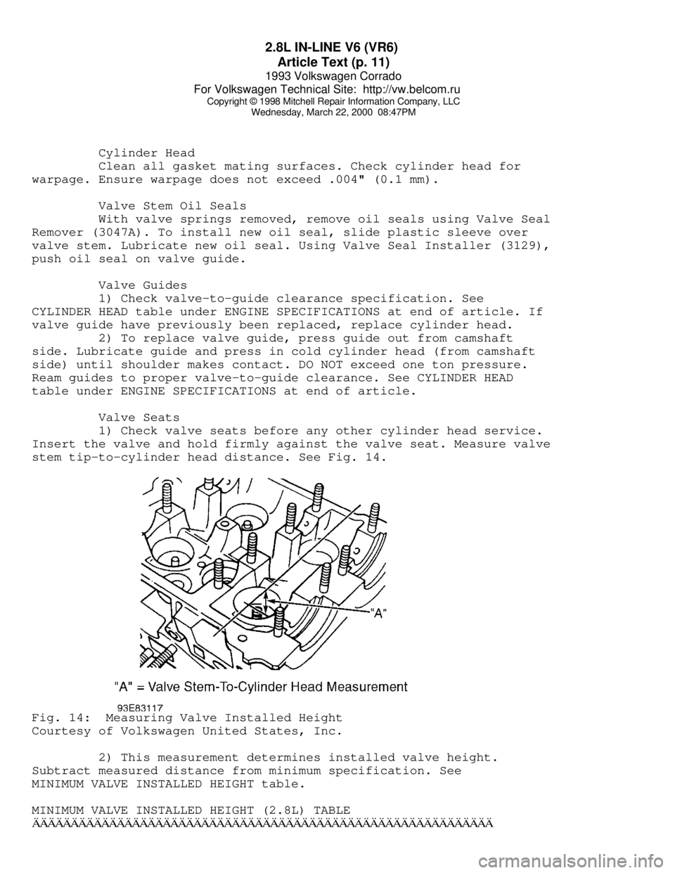
Insert the valve and hold firmly against the valve seat. Measure valve
stem tip-to-cylinder head distance. See Fig. 14.Fig. 14: Measuring Valve Installed Height
Courtesy of Volkswagen United States, Inc.
2) This measurement determines installed valve height.
Subtract measured distance from minimum specification. See
MINIMUM VALVE INSTALLED HEIGHT table.
MINIMUM VALVE INSTALLED HEIGHT (2.8L) TABLEÄÄÄÄÄÄÄÄÄÄÄÄÄÄÄÄÄÄÄÄÄÄÄÄÄÄÄÄÄÄÄÄÄÄÄÄÄÄÄÄÄÄÄÄÄÄÄÄÄÄÄÄÄÄÄÄÄÄÄÄ
Page 539 of 920
ENGINE OVERHAUL PROCEDURES - GENERAL INFORMATION
Article Text (p. 10)
1993 Volkswagen Corrado
For Volkswagen Technical Site: http://vw.belcom.ru
Copyright © 1998 Mitchell Repair Information Company, LLC
Wednesday, March 22, 2000 09:09PM
Replacing Valve Guide
Replace valve guide if clearance exceeds specification. Valve
guides are either pressed, hammered or shrunk in place, depending upon
cylinder head design and type of metal used.
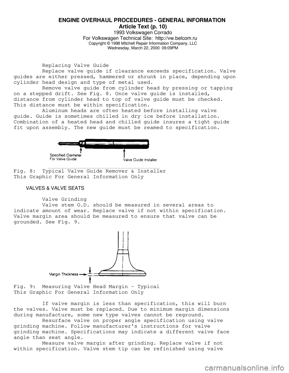
Remove valve guide from cylinder head by pressing or tapping
on a stepped drift. See Fig. 8. Once valve guide is installed,
distance from cylinder head to top of valve guide must be checked.
This distance must be within specification.
Aluminum heads are often heated before installing valve
guide. Guide is sometimes chilled in dry ice before installation.
Combination of a heated head and chilled guide insures a tight guide
fit upon assembly. The new guide must be reamed to specification.Fig. 8: Typical Valve Guide Remover & Installer
This Graphic For General Information Only
VALVES & VALVE SEATS
Valve Grinding
Valve stem O.D. should be measured in several areas to
indicate amount of wear. Replace valve if not within specification.
Valve margin area should be measured to ensure that valve can be
grounded. See Fig. 9.Fig. 9: Measuring Valve Head Margin - Typical
This Graphic For General Information Only
If valve margin is less than specification, this will burn
the valves. Valve must be replaced. Due to minimum margin dimensions
during manufacture, some new type valves cannot be reground.
Resurface valve on proper angle specification using valve
grinding machine. Follow manufacturer's instructions for valve
grinding machine. Specifications may indicate a different valve face
angle than seat angle.
Measure valve margin after grinding. Replace valve if not
within specification. Valve stem tip can be refinished using valve
Page 540 of 920
ENGINE OVERHAUL PROCEDURES - GENERAL INFORMATION
Article Text (p. 11)
1993 Volkswagen Corrado
For Volkswagen Technical Site: http://vw.belcom.ru
Copyright © 1998 Mitchell Repair Information Company, LLC
Wednesday, March 22, 2000 09:09PM
grinding machine.
Valve Lapping
During valve lapping of recent designed valves, be sure to
follow manufacturers recommendations. Surface hardening and materials
used with some valves do not permit lapping. Lapping process will
remove excessive amounts of the hardened surface.
Valve lapping is done to ensure adequate sealing between
valve face and seat. Use either a hand drill or lapping stick with
suction cup attached.
Moisten and attach suction cup to valve. Lubricate valve stem
and guide. Apply a thin coat of fine valve grinding compound between
valve and seat. Rotate lapping tool between the palms or with hand
drill.
Lift valve upward off the seat and change position often.
This is done to prevent grooving of valve seat. Lap valve until a
smooth polished seat is obtained. Thoroughly clean grinding compound
from components. Valve to valve seat concentricity should be checked.
See VALVE SEAT CONCENTRICITY.
CAUTION: Valve guides must be in good condition and free of carbon
deposits prior to valve seat grinding. Some engines contain
an induction hardened valve seat. Excessive material removal
will damage valve seats.
Valve Seat Grinding
Select coarse stone of correct size and angle for seat to be
ground. Ensure stone is true and has a smooth surface. Select correct
size pilot for valve guide dimension. Install pilot in valve guide.
Lightly lubricate pilot shaft. Install stone on pilot. Move stone off
and on the seat approximately 2 times per second during grinding
operation.
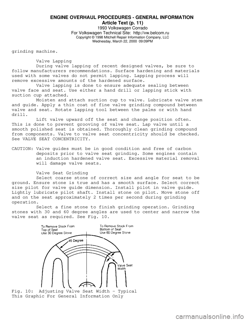
Select a fine stone to finish grinding operation. Grinding
stones with 30 and 60 degree angles are used to center and narrow the
valve seat as required. See Fig. 10.Fig. 10: Adjusting Valve Seat Width - Typical
This Graphic For General Information Only
Page 541 of 920
ENGINE OVERHAUL PROCEDURES - GENERAL INFORMATION
Article Text (p. 12)
1993 Volkswagen Corrado
For Volkswagen Technical Site: http://vw.belcom.ru
Copyright © 1998 Mitchell Repair Information Company, LLC
Wednesday, March 22, 2000 09:09PM
Valve Seat Replacement
Replacement of valve seat inserts is done by cutting out
the old insert and machining an oversize insert bore. Replacement
oversize insert is usually chilled and the cylinder head is sometimes
warmed. Valve seat is pressed into the head. This operation requires
specialized machine shop equipment.
Valve Seat Concentricity
Using dial gauge, install gauge pilot in valve guide.
Position gauge arm on the valve seat. Adjust dial indicator to zero.
Rotate arm 360 degrees and note reading. Runout should not exceed
specification.
To check valve-to-valve seat concentricity, coat valve face
lightly with Prussian Blue dye. Install valve and rotate it on valve
seat. If pattern is even and entire seat is coated at valve contact
point, valve is concentric with the seat.
REASSEMBLY
Valve Stem Installed Height
Valve stem installed height must be checked when new valves
are installed or when valves or valve seats have been ground. Install
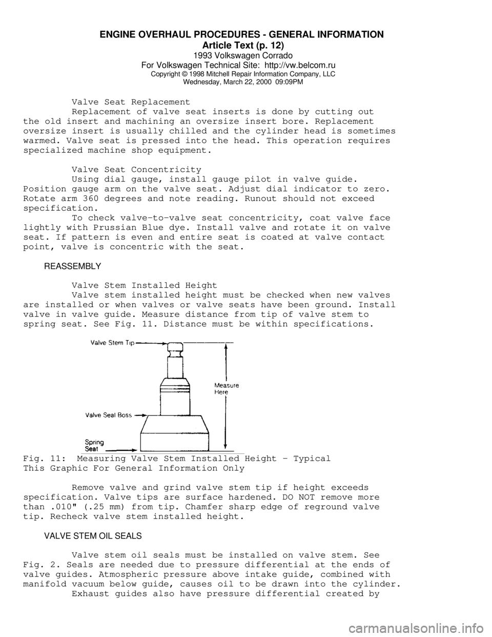
valve in valve guide. Measure distance from tip of valve stem to
spring seat. See Fig. 11. Distance must be within specifications.Fig. 11: Measuring Valve Stem Installed Height - Typical
This Graphic For General Information Only
Remove valve and grind valve stem tip if height exceeds
specification. Valve tips are surface hardened. DO NOT remove more
than .010" (.25 mm) from tip. Chamfer sharp edge of reground valve
tip. Recheck valve stem installed height.
VALVE STEM OIL SEALS
Valve stem oil seals must be installed on valve stem. See
Fig. 2. Seals are needed due to pressure differential at the ends of
valve guides. Atmospheric pressure above intake guide, combined with
manifold vacuum below guide, causes oil to be drawn into the cylinder.
Exhaust guides also have pressure differential created by
Page 542 of 920
ENGINE OVERHAUL PROCEDURES - GENERAL INFORMATION
Article Text (p. 13)
1993 Volkswagen Corrado
For Volkswagen Technical Site: http://vw.belcom.ru
Copyright © 1998 Mitchell Repair Information Company, LLC
Wednesday, March 22, 2000 09:09PM
exhaust gas flowing past the guide, creating a low pressure area. This
low pressure area draws oil into the exhaust system.
Replacement (On Vehicle)
Mark rocker arm or overhead cam components for location.
Remove rocker arm components or overhead cam components. Components
must be installed in original location. Remove spark plugs. Valve stem
oil seals may be replaced by holding valves against seats using air
pressure.
Air pressure must be installed in cylinder using an adapter
for spark plug hole. An adapter can be constructed by welding air hose
connection to spark plug body with porcelain removed.
Install adapter in spark plug hole. Apply a minimum of 140
psi (9.8 kg/cmý) to adapter. Air pressure should hold valve closed. If
air pressure does not hold valve closed, check for damaged or bent
valve. Cylinder head must be removed for service.
Using valve spring compressor, compress valve springs. Remove
valve locks. Carefully release spring compressor. Remove retainer or
rotator and valve spring. Remove valve stem oil seal.
If oversized valves have been installed, oversized oil seals
must be used. Coat valve stem with engine oil. Install protective
sleeve over end of valve stem. Install new oil seal over valve stem
and seat on valve guide. Remove protective sleeve. Install spring
seat, valve spring and retainer or rotator. Compress spring and
install valve locks. Remove spring compressor. Ensure valve locks
are fully seated.
Install rocker arms or overhead cam components. Tighten all
bolts to specification. Adjust valves if required. Remove adapter.
Install spark plugs, valve cover and gasket.
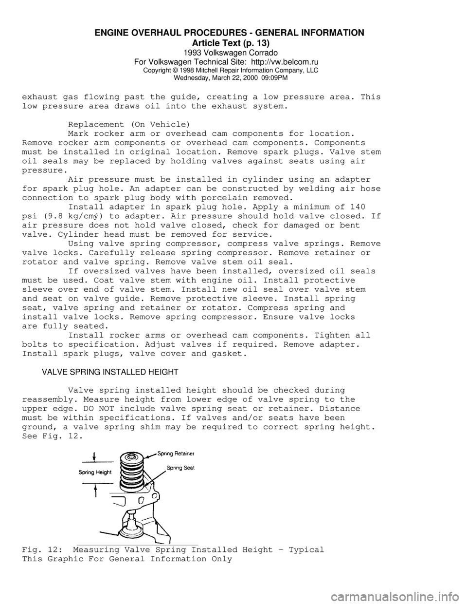
VALVE SPRING INSTALLED HEIGHT
Valve spring installed height should be checked during
reassembly. Measure height from lower edge of valve spring to the
upper edge. DO NOT include valve spring seat or retainer. Distance
must be within specifications. If valves and/or seats have been
ground, a valve spring shim may be required to correct spring height.
See Fig. 12.Fig. 12: Measuring Valve Spring Installed Height - Typical
This Graphic For General Information Only
Page 568 of 920

F - BASIC TESTING
Article Text (p. 3)
1993 Volkswagen Corrado
For Volkswagen Technical Site: http://vw.belcom.ru
Copyright © 1998 Mitchell Repair Information Company, LLC
Wednesday, March 22, 2000 09:10PM³ Jetta ³ 2.0L ³ ABA ³ Motronic MFI (2)³
³
³ 8-Valve ³ ³ ³
ÃÄÄÄÄÄÄÄÄÄÄÄÄÄÅÄÄÄÄÄÄÄÄÄÅÄÄÄÄÄÄÅÄÄÄÄÄÄÄÄÄÄÄÄÄÄÄÄÄ´
³ Passat GL
³ 2.0L ³ 9A ³ CIS-E Motronic ³
³
³16-Valve ³ ³ MFI (2) ³
ÃÄÄÄÄÄÄÄÄÄÄÄÄÄÅÄÄÄÄÄÄÄÄÄÅÄÄÄÄÄÄÅÄÄÄÄÄÄÄÄÄÄÄÄÄÄÄÄÄ´
³ Passat GLX
³ 2.8L VR6³ AAA ³ Motronic MFI (2)³
ÃÄÄÄÄÄÄÄÄÄÄÄÄÄÁÄÄÄÄÄÄÄÄÄÁÄÄÄÄÄÄÁÄÄÄÄÄÄÄÄÄÄÄÄÄÄÄÄÄ´
³(1) - California vehicles are equipped with
³
³ Digifant I.
³
³(2) - Sequential Multiport Fuel Injection.
³
ÀÄÄÄÄÄÄÄÄÄÄÄÄÄÄÄÄÄÄÄÄÄÄÄÄÄÄÄÄÄÄÄÄÄÄÄÄÄÄÄÄÄÄÄÄÄÄÄÄÙ FUEL PRESSURE
Basic diagnosis of fuel system should begin with determining
fuel system pressure.
WARNING: ALWAYS relieve fuel pressure before disconnecting any fuel
injection-related component. DO NOT allow fuel to contact
engine or electrical components.
CIS-E Motronic
1) Ensure ignition is off. Wrap a cloth around fuel
distributor port near cold start valve. Slowly loosen distributor port
near cold start valve to release fuel pressure. Connect fuel pressure
gauge between fuel distributor port and end of fuel line to cold start
valve. Disconnect differential pressure regulator harness connector.
2) Start engine and let it run. System fuel pressure should
89-96 psi (6.3-6.7 kg/cm
ý). If system fuel pressure is lower than
specification, perform fuel volume check. If fuel volume is okay,
replace fuel pressure regulator.
3) If fuel pressure is greater than specification, remove
return hose from pressure regulator and place in a container. Repeat
test. If system pressure is okay, check for restricted fuel return
line. If pressure is incorrect, replace fuel pressure regulator.
4) Turn ignition off. After 10 minutes, residual pressure
should be 48 psi (3.4 kg/cm
ý). After 20 minutes, residual pressure
should be 46 psi (3.2 kg/cm
ý). If system fuel pressure is low, check
fuel pump check valve, sensor plate free play, fuel distributor "O"
rings and seats. Replace if necessary. If these components are okay,
replace fuel pressure regulator.
Digifant
1) Ensure ignition is off. Wrap a cloth around service port
on fuel plenum. Slowly loosen service port on fuel plenum to release
fuel pressure. Install fuel pressure gauge at service port on fuel
plenum. Fuel pressure gauge must have reading range of 0-50 psi. Start
engine and allow it to idle. System fuel pressure should be
approximately 36 psi (2.5 kg/cm
ý).
2) Disconnect vacuum hose from top of fuel pressure
regulator. Fuel pressure should increase to approximately 44 psi (3
Page 823 of 920

TROUBLE SHOOTING - BASIC PROCEDURES
Article Text (p. 32)
1993 Volkswagen Corrado
For Volkswagen Technical Site: http://vw.belcom.ru
Copyright © 1998 Mitchell Repair Information Company, LLC
Wednesday, March 22, 2000 09:26PM
Loose rocker arms Retighten rocker arms,
See ENGINES
Excessive valve seat Reface valve seats, See
run-out ENGINES
Missing valve lock Install new valve lock
Excessively worn camshaft Replace camshaft, See
lobes ENGINES
Plugged valve lifter oil Eliminate restriction
holes or replace lifter
Faulty valve lifter check Replace lifter check
ball ball, See ENGINES
Rocker arm nut installed Remove and reinstall
upside down correctly
Valve lifter incorrect for Remove and replace
engine valve lifters
Faulty push rod seat or Replace plunger or push
lifter plunger rodÄÄÄÄÄÄÄÄÄÄÄÄÄÄÄÄÄÄÄÄÄÄÄÄÄÄÄÄÄÄÄÄÄÄÄÄÄÄÄÄÄÄÄÄÄÄÄÄÄÄÄÄÄÄÄÄÄÄÄÄÄÄÄÄÄÄÄÄÄÄNoisy Valves Improper valve lash Re-adjust valve lash,
See ENGINES
Worn or dirty valve lifters Clean and/or replace
lifters
Worn valve guides Replace valve guides,
See ENGINES
Excessive valve seat or Reface seats or valve
face run-out face
Worn camshaft lobes Replace camshaft, See
ENGINES
Loose rocker arm studs Re-tighten rocker arm
studs, See ENGINES
Bent push rods Replace push rods, See
ENGINES
Broken valve springs Replace valve springs,
See ENGINES
ÄÄÄÄÄÄÄÄÄÄÄÄÄÄÄÄÄÄÄÄÄÄÄÄÄÄÄÄÄÄÄÄÄÄÄÄÄÄÄÄÄÄÄÄÄÄÄÄÄÄÄÄÄÄÄÄÄÄÄÄÄÄÄÄÄÄÄÄÄÄBurned,Sticking Weak valve springs or Replace valves and/or
or Broken Valves warped valves springs, See ENGINES
Improper lifter clearance Re-adjust clearance or
replace lifters
Worn guides or improper Replace valve guides,
guide clearance See ENGINES
Out-of-round valve seats Re-grind valve seats
or improper seat width
Gum deposits on valve Remove deposits
stems, seats or guides
Improper spark timing Re-adjust spark timing
ÄÄÄÄÄÄÄÄÄÄÄÄÄÄÄÄÄÄÄÄÄÄÄÄÄÄÄÄÄÄÄÄÄÄÄÄÄÄÄÄÄÄÄÄÄÄÄÄÄÄÄÄÄÄÄÄÄÄÄÄÄÄÄÄÄÄÄÄÄÄBroken Undersize pistons Replace with larger
Pistons/Rings pistons, See ENGINES
Wrong piston rings Replace with correct
rings, See ENGINES
Out-of-round cylinder bore Re-bore cylinder bore