1993 VOLKSWAGEN CORRADO jump start
[x] Cancel search: jump startPage 414 of 920

ANTI-LOCK BRAKE SYSTEM
Article Text (p. 4)
1993 Volkswagen Corrado
For Volkswagen Technical Site: http://vw.belcom.ru
Copyright © 1998 Mitchell Repair Information Company, LLC
Wednesday, March 22, 2000 08:57PM
HYDRAULIC MODULATOR/PUMP
Depressurize brake system. See DEPRESSURIZING BRAKE SYSTEM.
Turn ignition on. Hydraulic modulator/pump should operate for 60
seconds maximum and then stop. Depress brake pedal a few times; pump
should operate again for a few seconds. If pump motor does not
operate, check electrical system. If pump motor operates for more than
60 seconds, internal or external hydraulic leak may be indicated.
Check for external leaks. If external leak is not found, further
testing may be needed to check for internal leaks.
ANTILOCK WARNING LIGHT
Start engine. ANTILOCK warning light should come on, then
turn off after a few seconds. If light does not come on when engine is
started, check electrical system. If light comes on and stays on,
fault has been detected by the ECU and testing will be needed. See
SYSTEM TESTING under DIAGNOSIS & TESTING.
DIAGNOSIS & TESTING
SYSTEM TESTING
NOTE: Check battery condition, brake fluid level, electrical
connections and wiring for damage. If fluid level is
incorrect or battery and/or electrical connections are
faulty, correct problem before preceding. Perform each step,
in sequence, to test entire system, except for ECU. If
faulty ECU is suspected, replace with a known good one, and
retest system. Unplug ECU connector for all test steps.
Power-To-ECU Test
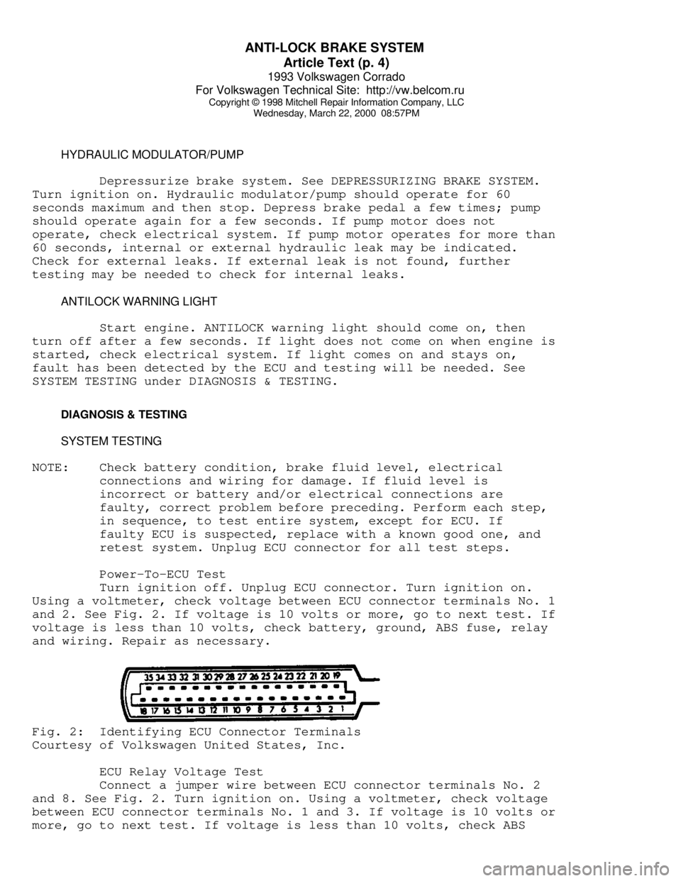
Turn ignition off. Unplug ECU connector. Turn ignition on.
Using a voltmeter, check voltage between ECU connector terminals No. 1
and 2. See Fig. 2. If voltage is 10 volts or more, go to next test. If
voltage is less than 10 volts, check battery, ground, ABS fuse, relay
and wiring. Repair as necessary.Fig. 2: Identifying ECU Connector Terminals
Courtesy of Volkswagen United States, Inc.
ECU Relay Voltage Test
Connect a jumper wire between ECU connector terminals No. 2
and 8. See Fig. 2. Turn ignition on. Using a voltmeter, check voltage
between ECU connector terminals No. 1 and 3. If voltage is 10 volts or
more, go to next test. If voltage is less than 10 volts, check ABS
Page 569 of 920

F - BASIC TESTING
Article Text (p. 4)
1993 Volkswagen Corrado
For Volkswagen Technical Site: http://vw.belcom.ru
Copyright © 1998 Mitchell Repair Information Company, LLC
Wednesday, March 22, 2000 09:10PM
kg/cmý). Turn engine off. After 10 minutes, residual pressure should
be 29 psi (2 kg/cm
ý). If system pressure is too high, replace fuel
pressure regulator.
3) If residual pressure is too low, operate engine until
system pressure builds up, then pinch off Blue fuel return line. If
pressure holds, replace the fuel regulator. If fuel pressure is low,
check for leaks at fuel lines, fuel injectors and fuel pump check
valve
TRANSFER PUMP CHECK
Transfer Pump Fuel Volume Check
1) Turn ignition off. To check transfer pump (in tank),
remove rear seat. Remove fuel sending unit access cover. Disconnect
ignition coil secondary wire and jumper to ground.
2) With transmission in Neutral, crank engine for 3-4
seconds. While starter is turning and for a few seconds afterwards, an
audible sound should be heard at the pump. If sound is not heard, go
to next step. If sound is heard, go to step 5).
3) Remove fuel pump relay from relay panel. On Corrado and
Passat, activate fuel pumps using Remote Control (VAG 1348/3A). On all
other models, activate fuel pumps using Remote Control (US 4480/3). On
all models, if pump does not operate, remove transfer pump wire
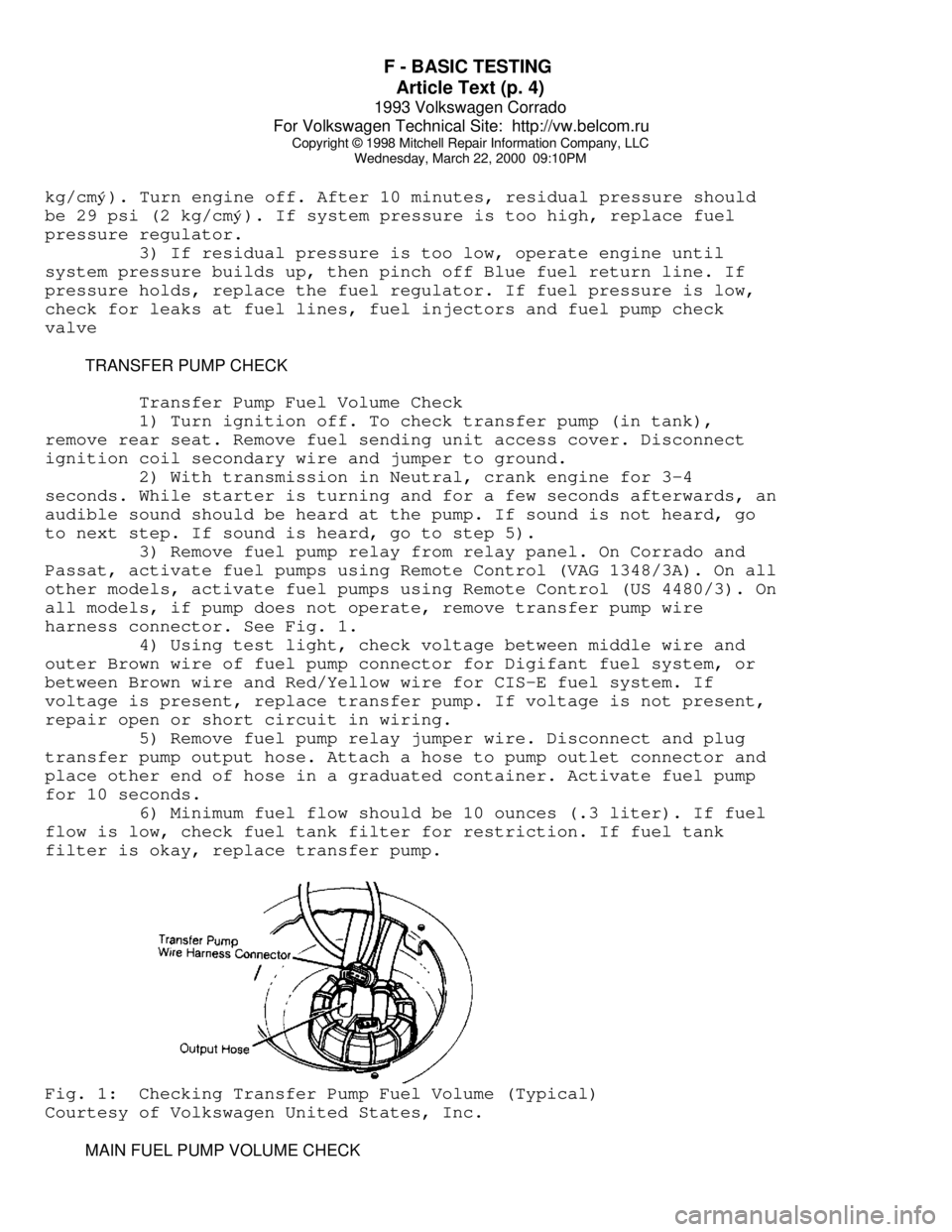
harness connector. See Fig. 1.
4) Using test light, check voltage between middle wire and
outer Brown wire of fuel pump connector for Digifant fuel system, or
between Brown wire and Red/Yellow wire for CIS-E fuel system. If
voltage is present, replace transfer pump. If voltage is not present,
repair open or short circuit in wiring.
5) Remove fuel pump relay jumper wire. Disconnect and plug
transfer pump output hose. Attach a hose to pump outlet connector and
place other end of hose in a graduated container. Activate fuel pump
for 10 seconds.
6) Minimum fuel flow should be 10 ounces (.3 liter). If fuel
flow is low, check fuel tank filter for restriction. If fuel tank
filter is okay, replace transfer pump.Fig. 1: Checking Transfer Pump Fuel Volume (Typical)
Courtesy of Volkswagen United States, Inc.
MAIN FUEL PUMP VOLUME CHECK
Page 583 of 920

G - TESTS W/CODES
Article Text
1993 Volkswagen Corrado
For Volkswagen Technical Site: http://vw.belcom.ru
Copyright © 1998 Mitchell Repair Information Company, LLC
Wednesday, March 22, 2000 09:11PM
ARTICLE BEGINNING
1993 ENGINE PERFORMANCE
Volkswagen Self-Diagnostics
Corrado SLC
INTRODUCTION
If no faults were found while performing preliminary
inspection procedures, proceed with self-diagnostics. If no fault
codes or only pass codes are present after entering self-diagnostics,
proceed to H - TESTS W/O CODES article for diagnosis by symptom (i.e.,
ROUGH IDLE, NO START, etc.).
NOTE: Scan Tester (VAG 1551) must be used to make full use of the
self-diagnostic system capabilities.
SELF-DIAGNOSTIC SYSTEM DESCRIPTION
Hard Failures
Hard failures of monitored sensors and/or components, cause
Malfunction Indicator Light (MIL) to come on and remain on until
problem is repaired. If malfunction indicator CHECK ENGINE light comes
on and remains on during vehicle operation, cause of malfunction must
be determined.
If malfunctions are present for more than 5 seconds, they are
stored as Diagnostic Trouble Codes (DTCs) and will be displayed as a
permanent malfunction even though the malfunction is not occurring at
the time DTCs are displayed. Malfunctions that affect oxygen sensor
control can only be read accurately after a test drive of at least 5
minutes.
Intermittent Failures
If a malfunction occurs for a maximum of 5 seconds, they are
stored and considered to be "sporadic" (intermittent failures). When
displayed on scan tester, malfunctions will have "SP" (sporadic) code.
RETRIEVING CODES
NOTE: See ENTERING SELF-DIAGNOSTICS for additional scan tester
operating instructions.
Corrado SLC
1) Turn ignition on. Connect Jumper Cable (357 971 514E) to
Data Link Connectors (DLC) located in center console. See Fig. 1.
Black end of jumper cable attaches to Black data link connector; White
end of cable attaches to White connector.
2) Leave jumper cable attached for 5 seconds, until on-board
diagnostic CHECK ENGINE light begins to blink. Remove jumper cable.
Allow on-board diagnostic code retrieval procedure to run until Code
Page 633 of 920

J - PIN VOLTAGE CHARTS
Article Text (p. 4)
1993 Volkswagen Corrado
For Volkswagen Technical Site: http://vw.belcom.ru
Copyright © 1998 Mitchell Repair Information Company, LLC
Wednesday, March 22, 2000 09:14PM
Connector & Jumper
Terminals No 1 & 2. ... 1.5 Ohms Max.
EGR Temperature
Sensor (15 & 33) ....... Disconnect Sensor
Connector & Jumper
Terminals No 1 & 2. ... 1.5 Ohms Max.
(1) - TESTING CONDITIONS: Disconnect harness connector from ECM.
Connect Test Box (VAG 1598/18) to ECM harness connector, leaving
the ECM disconnected.
(2) - With ignition off, jumper terminals No. 9 and No. 55 of the
test box.
(3) - Refer to the I - SYS/COMP TESTS article.
(4) - These are terminal connectors at data link connector.
(5) - 3-pin connector is located at rear of engine mount.
(6) - 3-pin Black connector is located next to starter.
(7) - 3-pin White connector is located next to starter.ÄÄÄÄÄÄÄÄÄÄÄÄÄÄÄÄÄÄÄÄÄÄÄÄÄÄÄÄÄÄÄÄÄÄÄÄÄÄÄÄÄÄÄÄÄÄÄÄÄÄÄÄÄÄÄÄÄÄÄÄÄÄÄÄÄÄÄÄÄÄEND OF ARTICLE