1993 VOLKSWAGEN CORRADO technical specifications
[x] Cancel search: technical specificationsPage 776 of 920

SUSPENSION - REAR
Article Text (p. 3)
1993 Volkswagen Corrado
For Volkswagen Technical Site: http://vw.belcom.ru
Copyright © 1998 Mitchell Repair Information Company, LLC
Wednesday, March 22, 2000 09:24PM
Removal
1) With vehicle on floor, remove plastic cap which covers
upper strut/shock retaining nuts. Remove strut/shock retaining nuts.
Slowly raise vehicle until weight is off spring. Remove bolt which
retains lower end of strut/shock absorber to axle beam mount. Raise
vehicle until strut/shock can be removed. Place strut/shock assembly
in vise.
2) Hold piston rod. Remove strut/shock retaining nut and
related components. See Fig. 1. Remove slotted nut (some models).
Remove spacer and coil spring. If coil spring is to be replaced,
ensure paint stripe color on replacement spring matches original
spring color stripe.
Installation
1) Install protective cap and tube onto shock absorber.
Install rubber buffer with small end downward. Install snap ring and
washer. Place spring into lower seat. Install upper retainer with
spacer sleeve.
2) Tighten slotted nut (some models) which retains piston
rod. Install upper mounting hardware. Tighten piston rod. To complete
installation, reverse removal procedure. Tighten bolts and nuts to
specification. See TORQUE SPECIFICATIONS table at end of article.
SUSPENSION ASSEMBLY
CAUTION: When removing suspension assembly, add weight to rear of
vehicle to prevent tipping due to change in center of
gravity.
Removal
1) With vehicle on floor, disconnect upper strut/shock mount.
Raise and support vehicle. Disconnect parking brake at bracket near
axle mount.
2) Disconnect and plug brakelines. Leave flex hose attached
to suspension. Separate brake pressure regulator spring from axle beam
(if equipped). Remove nuts which retain axle beam to body.
NOTE: DO NOT install bolts and nuts fouled with undercoating. With
waxy coating on threads, true tightening torque cannot be
measured. Clean or replace bolts and nuts.
Installation
1) If axle beam mounting has been removed, adjust mounting
pad. See Fig. 2. If pad is not correctly aligned, torsional preload of
mounting bushings will be incorrect.
2) Position rear suspension on body. Install nuts retaining
axle beam to body. Raise wheel. Guide upper end of strut/shock into
body mount.
3) Connect parking brake cables. Connect brakelines. Lower
vehicle. Tighten upper strut/shock retaining nuts. Tighten all bolts
and nuts to specification. Bleed brake system.
Page 777 of 920

SUSPENSION - REAR
Article Text (p. 4)
1993 Volkswagen Corrado
For Volkswagen Technical Site: http://vw.belcom.ru
Copyright © 1998 Mitchell Repair Information Company, LLC
Wednesday, March 22, 2000 09:24PM
WHEEL BEARING
Removal (Disc Brakes)
Raise and support vehicle. Remove wheel assembly. Remove
caliper assembly and support it out of work area. Remove dust cap,
cotter pin, hub nut, and thrust washer. Remove brake disc. Using a
long drift, tap bearings, races, and grease seal from disc hub.
Installation (Disc Brakes)
1) Clean hub cavity thoroughly. Using Bearing Race Installer
(VW 432 and VW 411), press inner and outer bearing races into bore.
Lubricate and install inner bearing. Using Seal Installer (VW 295 and
3074), tap grease seal into bore.
2) Install brake disc, outer bearing, thrust washer, and hub
nut. Reverse removal procedure to complete installation. Adjust wheel
bearing. See WHEEL BEARING under ADJUSTMENTS & INSPECTION. Install NEW
cotter pin.
Removal (Drum Brakes)
Raise and support vehicle. Remove wheel assembly. Remove dust
cap, cotter pin, hub nut, and thrust washer. Remove brake drum. Using
a long drift, tap bearings, races, and grease seal from hub.
Installation (Drum Brakes)
1) Clean hub cavity thoroughly. Using Outer Bearing Race
Installer (VW 431 and VW 411), press outer bearing race into bore.
Using Inner Bearing Race Installer (VW 432 and VW 411), press inner
bearing race into bore. Lubricate and install inner bearing. Using
Seal Installer (VW 295 and 3074), tap grease seal into bore.
2) Install brake drum, outer bearing, thrust washer, and hub
nut. Reverse removal procedure to complete installation. Adjust wheel
bearing. See WHEEL BEARING under ADJUSTMENTS & INSPECTION. Install NEW
cotter pin.
TORQUE SPECIFICATIONS
TORQUE SPECIFICATIONS TABLEÄÄÄÄÄÄÄÄÄÄÄÄÄÄÄÄÄÄÄÄÄÄÄÄÄÄÄÄÄÄÄÄÄÄÄÄÄÄÄÄÄÄÄÄÄÄÄÄÄÄÄÄÄÄÄApplication Ft. Lbs. (N.m)
Brake Caliper Bolt .......................... 48 (65)
Coil Spring Retainer-To-Piston Rod Nut ...... 11 (15)
Rear Axle Beam Pivot Bushing Bolt ........... 43 (58)
Rear Axle Mounting Pad-To-Body Bolt ......... 63 (85)
Shock Absorber Slot Nut ..................... 15 (20)
Shock Absorber-To-Axle Beam Nut ............. 52 (70)
Shock Absorber-To-Body Bolt ................. 26 (35)
Stub Axle-To-Control Arm Bolt ............... 44 (60)
Wheel Lug Bolt ............................. 81 (110)
ÄÄÄÄÄÄÄÄÄÄÄÄÄÄÄÄÄÄÄÄÄÄÄÄÄÄÄÄÄÄÄÄÄÄÄÄÄÄÄÄÄÄÄÄÄÄÄÄÄÄÄÄÄÄÄEND OF ARTICLE
Page 784 of 920

TRANSMISSION REMOVAL & INSTALLATION - A/T
Article Text
1993 Volkswagen Corrado
For Volkswagen Technical Site: http://vw.belcom.ru
Copyright © 1998 Mitchell Repair Information Company, LLC
Wednesday, March 22, 2000 09:25PM
ARTICLE BEGINNING
TRANSMISSION SERVICING
Volkswagen Transmission Removal & Installation - Automatic
Corrado SLC, Passat
REMOVAL & INSTALLATION
REMOVAL
1) Obtain radio code. Disconnect negative battery cable.
Remove air ducts to brake caliper and engine air intake. Disconnect
speedometer cable from transaxle.
2) Remove upper transaxle-to-engine bolts. Disconnect and
plug transaxle cooler lines. Support engine from above. Remove
starter. Disconnect accelerator and selector cables from transaxle.
3) Remove left transaxle mount and support. Remove electrical
wiring from transaxle. Remove lower bolts on front mount and remove
mount.
4) Place mating marks on axle shaft flanges. Remove left and
right axle shaft flange bolts. Disconnect right strut-to-spindle
bolts. Remove right side axle. Reconnect strut. Remove protective
plate from transaxle.
5) Remove torque converter-to-drive plate bolts. Slightly
lower engine assembly. Support transaxle with jack. Remove lower
transaxle-to-engine mounting bolts. Lower transaxle.
INSTALLATION
To install, reverse removal procedure. Adjust accelerator and
selector cables if necessary. Use NEW self-locking nuts. Tighten bolts
to specification. See TORQUE SPECIFICATIONS.
TORQUE SPECIFICATIONS
TORQUE SPECIFICATIONS TABLEÄÄÄÄÄÄÄÄÄÄÄÄÄÄÄÄÄÄÄÄÄÄÄÄÄÄÄÄÄÄÄÄÄÄÄÄÄÄÄÄÄÄÄÄÄÄÄÄÄÄÄÄÄÄÄÄÄÄÄÄApplications Ft. Lbs. (N.m)
Axle Shaft Nut ................................. 195 (265)
Axle Shaft-To-Flange Bolts ....................... 33 (45)
Engine Mount Bolts ............................... 33 (45)
Strut-To-Spindle Bolts ........................... 70 (95)
Torque Converter-To-Drive Plate Bolts ............ 44 (60)
Transaxle-To-Engine
M10 Bolts ...................................... 44 (60)
M12 Bolts ...................................... 59 (80)
ÄÄÄÄÄÄÄÄÄÄÄÄÄÄÄÄÄÄÄÄÄÄÄÄÄÄÄÄÄÄÄÄÄÄÄÄÄÄÄÄÄÄÄÄÄÄÄÄÄÄÄÄÄÄÄÄÄÄÄÄEND OF ARTICLE
Page 787 of 920

TRANSMISSION REMOVAL & INSTALLATION - M/T
Article Text (p. 3)
1993 Volkswagen Corrado
For Volkswagen Technical Site: http://vw.belcom.ru
Copyright © 1998 Mitchell Repair Information Company, LLC
Wednesday, March 22, 2000 09:25PM
Wipe off excess grease. If flywheel was removed, reinstall on engine.
Using flywheel lock or similar device, hold engine from turning.
Tighten flywheel bolts to specification. See TORQUE SPECIFICATIONS
table at end of article.
2) Mount clutch disk and pressure plate on engine. Install
pressure plate bolts finger tight. Using Clutch Centering Plug (3190),
align clutch disk and pilot bushing holes. Tighten pressure plate
bolts to specification using a crisscross pattern.
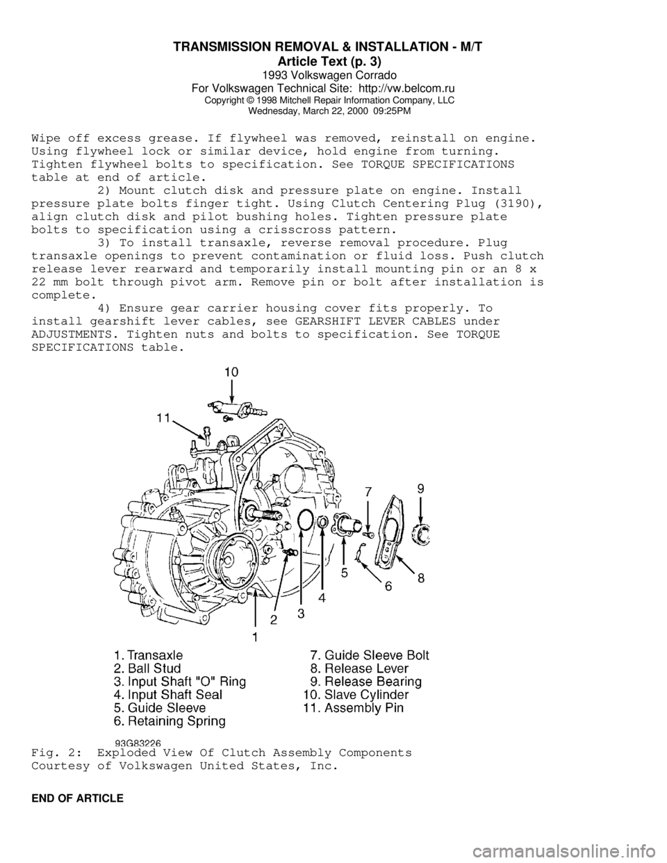
3) To install transaxle, reverse removal procedure. Plug
transaxle openings to prevent contamination or fluid loss. Push clutch
release lever rearward and temporarily install mounting pin or an 8 x
22 mm bolt through pivot arm. Remove pin or bolt after installation is
complete.
4) Ensure gear carrier housing cover fits properly. To
install gearshift lever cables, see GEARSHIFT LEVER CABLES under
ADJUSTMENTS. Tighten nuts and bolts to specification. See TORQUE
SPECIFICATIONS table.Fig. 2: Exploded View Of Clutch Assembly Components
Courtesy of Volkswagen United States, Inc.
END OF ARTICLE
Page 794 of 920

TROUBLE SHOOTING - BASIC PROCEDURES
Article Text (p. 3)
1993 Volkswagen Corrado
For Volkswagen Technical Site: http://vw.belcom.ru
Copyright © 1998 Mitchell Repair Information Company, LLC
Wednesday, March 22, 2000 09:25PM
Parallelism not to
specifications Reface or replace rotor
Wheel bearings not adjusted See SUSPENSION
Rear drums out-of-round Reface or replace drums
Disc pad reversed, steel
against rotor Remove and reinstall
padÄÄÄÄÄÄÄÄÄÄÄÄÄÄÄÄÄÄÄÄÄÄÄÄÄÄÄÄÄÄÄÄÄÄÄÄÄÄÄÄÄÄÄÄÄÄÄÄÄÄÄÄÄÄÄÄÄÄÄÄÄÄÄÄÄÄÄÄÄÄExcessive Pedal
Effort Malfunctioning power unit See POWER BRAKES or
BRAKE SYSTEM
Partial system failure Check fluid and pipes
Worn disc pad or lining Replace pad or lining
Caliper piston stuck or
sluggish See DISC BRAKES or
BRAKE SYSTEM
Master cylinder piston
stuck See MASTER CYLINDERS
or BRAKE SYSTEM
Brake fade due to incorrect
pads for linings Replace pads or linings
Linings or pads glazed Replace pads or linings
Worn drums Reface or replace drums
ÄÄÄÄÄÄÄÄÄÄÄÄÄÄÄÄÄÄÄÄÄÄÄÄÄÄÄÄÄÄÄÄÄÄÄÄÄÄÄÄÄÄÄÄÄÄÄÄÄÄÄÄÄÄÄÄÄÄÄÄÄÄÄÄÄÄÄÄÄÄExcessive Pedal
Travel Partial brake system failure Check fluid and pipes
Insufficient fluid in
master cylinder See MASTER CYLINDERS or
BRAKE SYSTEM
Air trapped in system See BRAKE BLEEDING or
BRAKE SYSTEM
Rear brakes not adjusted See Adjustments in DRUM
BRAKES or BRAKE SYSTEM
Bent shoe or lining See DRUM BRAKES or
BRAKE SYSTEM
Plugged master cylinder cap See MASTER CYLINDERS
or BRAKE SYSTEM
Page 895 of 920

WHEEL ALIGNMENT SPECIFICATIONS & PROCEDURES
Article Text
1993 Volkswagen Corrado
For Volkswagen Technical Site: http://vw.belcom.ru
Copyright © 1998 Mitchell Repair Information Company, LLC
Wednesday, March 22, 2000 09:27PM
ARTICLE BEGINNING
1993 WHEEL ALIGNMENT
Volkswagen Specifications & Procedures
Corrado SLC
* PLEASE READ THIS FIRST *
NOTE: Prior to performing wheel alignment, perform preliminary
visual and mechanical inspection of wheels, tires and
suspension components. See PRE-ALIGNMENT INSTRUCTIONS in
WHEEL ALIGNMENT THEORY/OPERATION article in the
GENERAL INFORMATION section.
WHEEL ALIGNMENT SPECIFICATIONS
WHEEL ALIGNMENT SPECIFICATIONS TABLEÄÄÄÄÄÄÄÄÄÄÄÄÄÄÄÄÄÄÄÄÄÄÄÄÄÄÄÄÄÄÄÄÄÄÄÄÄÄÄÄÄÄÄÄÄÄÄÄÄÄÄÄÄÄÄÄÄÄÄÄÄÄÄÄÄÄÄÄÄÄApplication Preferred Range
Corrado
Camber (1)
Front ............... -1 1/3 ....................... -1 To -1 2/3
Rear ................ -1 5/8 ................... -1 1/2 To -1 3/4
Caster (1) ........... 3 1/4 ..................... 2 3/4 To 3 3/4
Toe-In (2)
Front ................. 1/16 ................ 0 To 1/8 (0 To 3.2)
Rear ................ 1/4 (6.4) ......... 1/8 To 3/8 (3.2 To 9.6)
Toe-In (1)
Front ................. 1/8 ............................ 0 To 1/4
Rear .................. 1/2 .......................... 1/4 To 3/4
Toe-Out On Turns (1) .. 1 1/2 ..................... 1 1/4 To 1 3/4
(1) - Measurement is in degrees.
(2) - Measurement is in inches (mm).
ÄÄÄÄÄÄÄÄÄÄÄÄÄÄÄÄÄÄÄÄÄÄÄÄÄÄÄÄÄÄÄÄÄÄÄÄÄÄÄÄÄÄÄÄÄÄÄÄÄÄÄÄÄÄÄÄÄÄÄÄÄÄÄÄÄÄÄÄÄÄEND OF ARTICLE
Page 896 of 920

WHEEL ALIGNMENT THEORY/OPERATION
Article Text
1993 Volkswagen Corrado
For Volkswagen Technical Site: http://vw.belcom.ru
Copyright © 1998 Mitchell Repair Information Company, LLC
Wednesday, March 22, 2000 09:27PM
ARTICLE BEGINNING
GENERAL INFORMATION
Wheel Alignment Theory & Operation
ALL MODELS
* PLEASE READ THIS FIRST *
NOTE: This article is intended for general information purposes
only. This information may not apply to all makes and models.
PRE-ALIGNMENT INSTRUCTIONS
GENERAL ALIGNMENT CHECKS
Before adjusting wheel alignment, check the following:
* Each axle uses tires of same construction and tread style,
equal in tread wear and overall diameter. Verify that radial
and axial runout is not excessive. Inflation should be at
manufacturer's specifications.
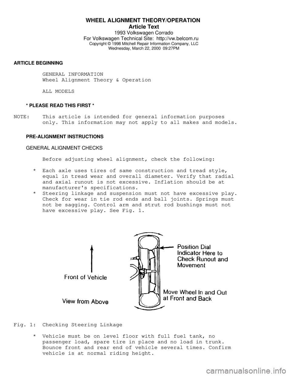
* Steering linkage and suspension must not have excessive play.
Check for wear in tie rod ends and ball joints. Springs must
not be sagging. Control arm and strut rod bushings must not
have excessive play. See Fig. 1.Fig. 1: Checking Steering Linkage
* Vehicle must be on level floor with full fuel tank, no
passenger load, spare tire in place and no load in trunk.
Bounce front and rear end of vehicle several times. Confirm
vehicle is at normal riding height.
Page 897 of 920

WHEEL ALIGNMENT THEORY/OPERATION
Article Text (p. 2)
1993 Volkswagen Corrado
For Volkswagen Technical Site: http://vw.belcom.ru
Copyright © 1998 Mitchell Repair Information Company, LLC
Wednesday, March 22, 2000 09:27PM
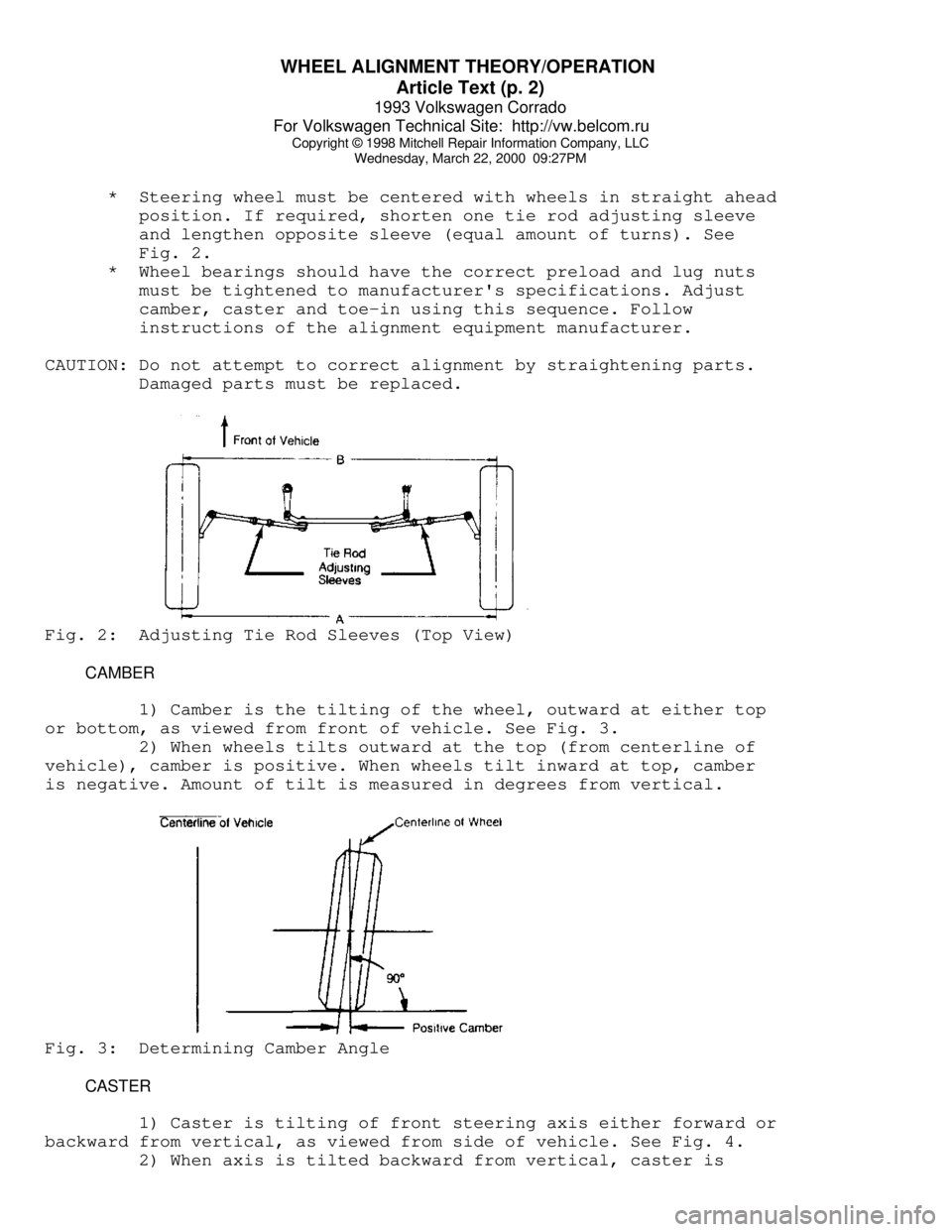
* Steering wheel must be centered with wheels in straight ahead
position. If required, shorten one tie rod adjusting sleeve
and lengthen opposite sleeve (equal amount of turns). See
Fig. 2.
* Wheel bearings should have the correct preload and lug nuts
must be tightened to manufacturer's specifications. Adjust
camber, caster and toe-in using this sequence. Follow
instructions of the alignment equipment manufacturer.
CAUTION: Do not attempt to correct alignment by straightening parts.
Damaged parts must be replaced.Fig. 2: Adjusting Tie Rod Sleeves (Top View)
CAMBER
1) Camber is the tilting of the wheel, outward at either top
or bottom, as viewed from front of vehicle. See Fig. 3.
2) When wheels tilts outward at the top (from centerline of
vehicle), camber is positive. When wheels tilt inward at top, camber
is negative. Amount of tilt is measured in degrees from vertical.Fig. 3: Determining Camber Angle
CASTER
1) Caster is tilting of front steering axis either forward or
backward from vertical, as viewed from side of vehicle. See Fig. 4.
2) When axis is tilted backward from vertical, caster is