1993 VOLKSWAGEN CORRADO technical specifications
[x] Cancel search: technical specificationsPage 747 of 920

STEERING GEAR - POWER RACK & PINION
Article Text (p. 4)
1993 Volkswagen Corrado
For Volkswagen Technical Site: http://vw.belcom.ru
Copyright © 1998 Mitchell Repair Information Company, LLC
Wednesday, March 22, 2000 09:23PM
Installation
To install, reverse removal procedure. Tighten nuts and bolts
to specification. See TORQUE SPECIFICATIONS table at end of article.
Fill and bleed hydraulic system. See HYDRAULIC SYSTEM BLEEDING. Check
wheel alignment. See WHEEL ALIGNMENT SPECIFICATIONS & PROCEDURES
article in the WHEEL ALIGNMENT section.
OVERHAUL
Manufacturer recommends that power steering pump and steering
gear be replaced, rather than be repaired.
TORQUE SPECIFICATIONS
TORQUE SPECIFICATIONS TABLEÄÄÄÄÄÄÄÄÄÄÄÄÄÄÄÄÄÄÄÄÄÄÄÄÄÄÄÄÄÄÄÄÄÄÄÄÄÄÄÄÄÄÄÄÄÄÄÄÄÄÄÄÄÄÄÄÄÄÄÄApplication Ft. Lbs. (N.m)
End Housing Bolt ................................. 37 (50)
Power Steering Pump Bolt ......................... 18 (25)
Pressure-Flow Limiting Valve Cap ................. 42 (57)
Pressure Line Fitting ............................ 29 (39)
Return Line Fitting
On Pump ........................................ 29 (39)
On Valve Housing ............................... 22 (30)
Steering Gear Retaining Bolt ..................... 24 (33)
Subframe Bolt
Long .......................................... 96 (130)
Short .......................................... 59 (80)
Tie Rod Lock Nut ................................. 42 (55)
Tie Rod-To-Steering Arm .......................... 32 (44)
Valve Housing Bolt ............................... 15 (20)
ÄÄÄÄÄÄÄÄÄÄÄÄÄÄÄÄÄÄÄÄÄÄÄÄÄÄÄÄÄÄÄÄÄÄÄÄÄÄÄÄÄÄÄÄÄÄÄÄÄÄÄÄÄÄÄÄÄÄÄÄEND OF ARTICLE
Page 755 of 920

SUSPENSION - FRONT
Article Text
1993 Volkswagen Corrado
For Volkswagen Technical Site: http://vw.belcom.ru
Copyright © 1998 Mitchell Repair Information Company, LLC
Wednesday, March 22, 2000 09:24PM
ARTICLE BEGINNING
1993 SUSPENSION
Volkswagen - Front
Corrado SLC
DESCRIPTION
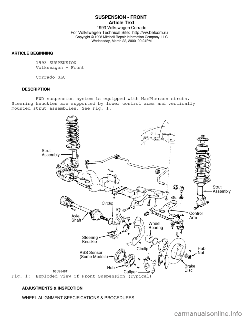
FWD suspension system is equipped with MacPherson struts.
Steering knuckles are supported by lower control arms and vertically
mounted strut assemblies. See Fig. 1.Fig. 1: Exploded View Of Front Suspension (Typical)
ADJUSTMENTS & INSPECTION
WHEEL ALIGNMENT SPECIFICATIONS & PROCEDURES
Page 756 of 920

SUSPENSION - FRONT
Article Text (p. 2)
1993 Volkswagen Corrado
For Volkswagen Technical Site: http://vw.belcom.ru
Copyright © 1998 Mitchell Repair Information Company, LLC
Wednesday, March 22, 2000 09:24PM
NOTE: See WHEEL ALIGNMENT SPECIFICATIONS & PROCEDURES article in
the WHEEL ALIGNMENT section.
WHEEL BEARING
No adjustment is required.
BALL JOINT CHECKING
Raise and support vehicle. Inspect ball joints for excessive
play and damaged rubber boots. There should be no vertical or
horizontal ball joint play. Replace ball joint if any play is present.
REMOVAL & INSTALLATION
HUB & KNUCKLE ASSEMBLY
Use exploded view illustration when removing or installing
hub and knuckle assembly. See Fig. 1.
LOWER CONTROL ARM & BALL JOINT
Removal
1) Raise and support vehicle. Remove bolt retaining ball
joint at steering knuckle. Separate ball joint from housing. Leave
control arm hanging in mounts at subframe.
2) If control arm is not to be removed and ball joint is
riveted to control arm, drill out ball joint rivets using a 9/32" (7
mm) drill. After drilling rivets, chisel off rivet heads (if
necessary). If ball joint is bolted to control arm, remove bolts.
Remove ball joint.
3) If control arm is to be removed from vehicle, remove
stabilizer bar link rod nut, washers, and bushings. Remove pivot bolt
and "U" bracket housing inner pivot pin. Slide out control arm.
NOTE: On vehicles with automatic transmission, engine may have to
be lifted slightly to gain access to pivot bolts.
Inspection
Check lower control arm bushings for excessive wear, cracks
or contamination. Replace bushings if necessary. To replace bushings,
press out worn bushing. Select new bushing and press into position.
Ensure bushing does not twist when seating into place.
Installation
Slide new ball joint into slot in control arm. Install and
tighten ball joint retaining bolts. Install lower control arm to
subframe. Install ball joint into steering knuckle. To complete
installation, reverse removal procedure. Tighten control arm bolts
with vehicle on ground. Tighten all bolts and nuts to specification.
See TORQUE SPECIFICATIONS table at end of article. Check wheel
Page 757 of 920

SUSPENSION - FRONT
Article Text (p. 3)
1993 Volkswagen Corrado
For Volkswagen Technical Site: http://vw.belcom.ru
Copyright © 1998 Mitchell Repair Information Company, LLC
Wednesday, March 22, 2000 09:24PM
alignment. See WHEEL ALIGNMENT SPECIFICATIONS & PROCEDURES article in
the WHEEL ALIGNMENT section.
STRUT ASSEMBLY
Removal
1) Raise and support vehicle. Remove wheel assembly.
Disconnect and wire caliper aside. Remove bolts retaining strut to
steering knuckle. Note top bolt is used for front wheel camber
adjustment.
2) Support front suspension arm and components. Pry
suspension strut from steering knuckle. Remove upper strut retaining
nuts from inside engine compartment. Remove strut assembly.
Installation
To install, reverse removal procedure. Tighten bolts and nuts
to specification. See TORQUE SPECIFICATIONS table at end of article.
Check wheel alignment. See WHEEL ALIGNMENT SPECIFICATIONS & PROCEDURES
article in the WHEEL ALIGNMENT section.
FRONT SUSPENSION ASSEMBLY
Removal
1) Raise and support vehicle at center with safety stands.
Disconnect brake line and plug openings. Leave flex line in place.
Remove stabilizer link rod nut, bushings and washers.
2) Remove tie rod nut. Separate tie rod from steering
knuckle. Disconnect inner portion of constant velocity joint from
transaxle drive flange.
3) Remove lower control arm front pivot bolt. Remove "U"
shaped bracket bolts at control arm rear pivot.
NOTE: On vehicles with automatic transmission, engine may have to
be lifted slightly to gain access to pivot bolts.
4) Support suspension assembly. Remove upper strut retaining
nuts. Remove suspension assembly from vehicle.
Installation
To install, reverse removal procedure. Ensure convex side of
thrust washer faces pivot bolt head. Tighten bolts and nuts to
specification. Check wheel alignment. Proceed to appropriate
WHEEL ALIGNMENT SPECIFICATIONS & PROCEDURES article in the WHEEL
ALIGNMENT section.
WHEEL BEARING
Removal
1) Remove axle shaft nut with front wheels on ground. Raise
and support vehicle. Allow suspension to hang free. Remove wheel
assembly. Remove brake caliper attaching bolts. Remove caliper and
wire aside. Remove brake disc retaining screw and remove disc.
Page 758 of 920

SUSPENSION - FRONT
Article Text (p. 4)
1993 Volkswagen Corrado
For Volkswagen Technical Site: http://vw.belcom.ru
Copyright © 1998 Mitchell Repair Information Company, LLC
Wednesday, March 22, 2000 09:24PM
2) Disconnect tie rod ball joint from steering knuckle.
Remove control arm ball joint clamp nut and bolt. Disconnect control
arm ball joint from steering knuckle. Remove steering knuckle.
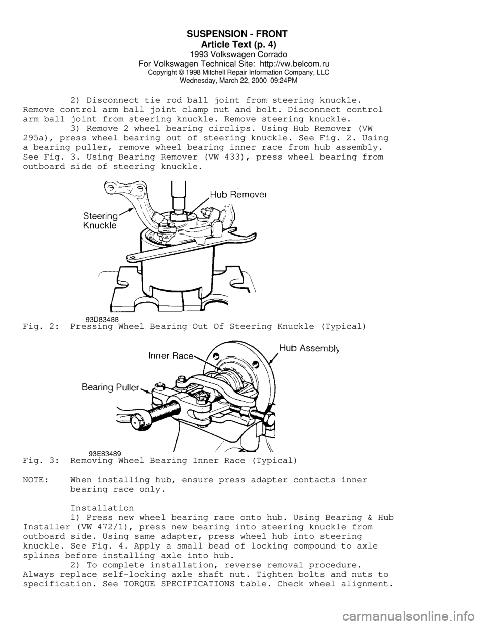
3) Remove 2 wheel bearing circlips. Using Hub Remover (VW
295a), press wheel bearing out of steering knuckle. See Fig. 2. Using
a bearing puller, remove wheel bearing inner race from hub assembly.
See Fig. 3. Using Bearing Remover (VW 433), press wheel bearing from
outboard side of steering knuckle.Fig. 2: Pressing Wheel Bearing Out Of Steering Knuckle (Typical)Fig. 3: Removing Wheel Bearing Inner Race (Typical)
NOTE: When installing hub, ensure press adapter contacts inner
bearing race only.
Installation
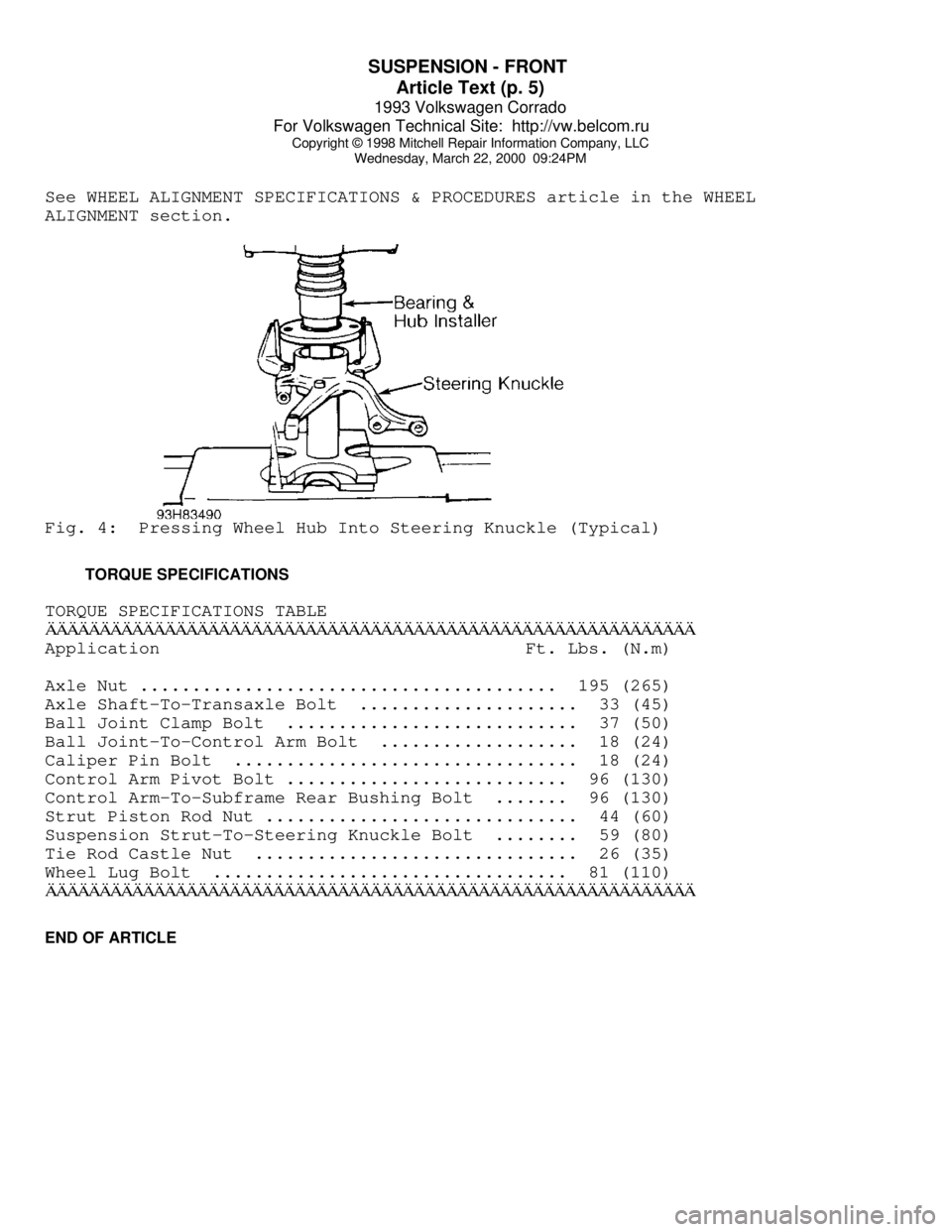
1) Press new wheel bearing race onto hub. Using Bearing & Hub
Installer (VW 472/1), press new bearing into steering knuckle from
outboard side. Using same adapter, press wheel hub into steering
knuckle. See Fig. 4. Apply a small bead of locking compound to axle
splines before installing axle into hub.
2) To complete installation, reverse removal procedure.
Always replace self-locking axle shaft nut. Tighten bolts and nuts to
specification. See TORQUE SPECIFICATIONS table. Check wheel alignment.
Page 759 of 920

SUSPENSION - FRONT
Article Text (p. 5)
1993 Volkswagen Corrado
For Volkswagen Technical Site: http://vw.belcom.ru
Copyright © 1998 Mitchell Repair Information Company, LLC
Wednesday, March 22, 2000 09:24PM
See WHEEL ALIGNMENT SPECIFICATIONS & PROCEDURES article in the WHEEL
ALIGNMENT section.Fig. 4: Pressing Wheel Hub Into Steering Knuckle (Typical)
TORQUE SPECIFICATIONS
TORQUE SPECIFICATIONS TABLEÄÄÄÄÄÄÄÄÄÄÄÄÄÄÄÄÄÄÄÄÄÄÄÄÄÄÄÄÄÄÄÄÄÄÄÄÄÄÄÄÄÄÄÄÄÄÄÄÄÄÄÄÄÄÄÄÄÄÄÄApplication Ft. Lbs. (N.m)
Axle Nut ........................................ 195 (265)
Axle Shaft-To-Transaxle Bolt ..................... 33 (45)
Ball Joint Clamp Bolt ............................ 37 (50)
Ball Joint-To-Control Arm Bolt ................... 18 (24)
Caliper Pin Bolt ................................. 18 (24)
Control Arm Pivot Bolt ........................... 96 (130)
Control Arm-To-Subframe Rear Bushing Bolt ....... 96 (130)
Strut Piston Rod Nut .............................. 44 (60)
Suspension Strut-To-Steering Knuckle Bolt ........ 59 (80)
Tie Rod Castle Nut ............................... 26 (35)
Wheel Lug Bolt .................................. 81 (110)
ÄÄÄÄÄÄÄÄÄÄÄÄÄÄÄÄÄÄÄÄÄÄÄÄÄÄÄÄÄÄÄÄÄÄÄÄÄÄÄÄÄÄÄÄÄÄÄÄÄÄÄÄÄÄÄÄÄÄÄÄEND OF ARTICLE
Page 760 of 920

VR65 ENGINE: AFFIX NEW VACUUM HOSE ROUTING LABEL
Article Text
1993 Volkswagen Corrado
For Volkswagen Technical Site: http://vw.belcom.ru
Copyright © 1998 Mitchell Repair Information Company, LLC
Wednesday, March 22, 2000 09:26PM
ARTICLE BEGINNING
EMISSION RECALL BULLETIN
VACUUM HOSE ROUTING LABEL REPLACEMENT - RECALL CODE SQ
Model(s): 1992-93 Volkswagen Corrado VR6
Recall No.: SQ
Date: July 6, 1993
Number of Affected Vehicles: 4,300
Beginning Date of Manufacture: August 1991
Ending Date of Manufacture: November 1992
DEFECT INFORMATION REPORT
1. Manufacturer: Volkswagen AG (VWAG)
Importer: Volkswagen of America, Inc. (VWoA)
2. Description of the Defect:
Volkswagen has found that affected Corrado VR6 vehicles were
inadvertently equipped during assembly with a label containing
emission specifications intended and applicable to Passat model
VR6 vehicles. The diagram of the vacuum hose routing is
incorrect as applied to the Corrado.
3. Class or Category of Vehicles Potentially Affected:
The affected vehicles are 1992 and early production model 1993
Volkswagen Corrado VR6 vehicles equipped with a VR6 engine,
identified by the following engine families:
1992 1993
ÄÄÄÄÄÄÄÄÄÄÄÄ ÄÄÄÄÄÄÄÄÄÄÄÄ California and 49-State NVW2.8V5FWE7 PVW2.8V5FWE9
PVW2.8V5FWH1
4.1. Number of Vehicles Estimated to Have the Defect:
According to Volkswagen's records, a total of approximately
3,625 49-states and 675 California equipped vehicles are
affected. These vehicles were manufactured from August 1991
through November 1992 and are within the following vehicle
identification number range:
WVW___50_NK000001 - WVW___50_PK005031
Other Description: Vehicles equipped with VR6 engines
4.2. Production Plants: Wilhelm Karmann GmbH
Osnabrueck Plant
Page 774 of 920

SUSPENSION - REAR
Article Text
1993 Volkswagen Corrado
For Volkswagen Technical Site: http://vw.belcom.ru
Copyright © 1998 Mitchell Repair Information Company, LLC
Wednesday, March 22, 2000 09:24PM
ARTICLE BEGINNING
1993 SUSPENSION
Volkswagen Rear
Corrado SLC
DESCRIPTION
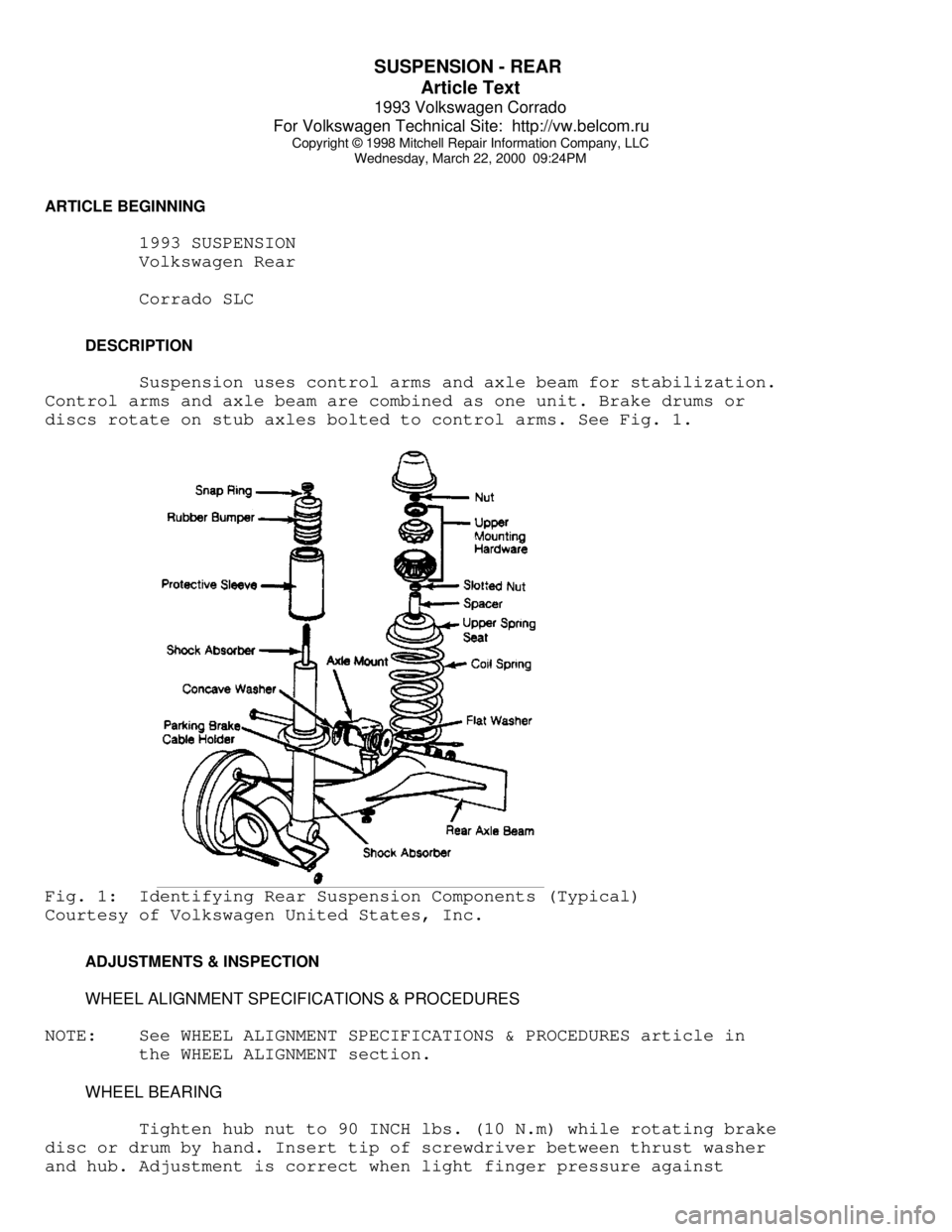
Suspension uses control arms and axle beam for stabilization.
Control arms and axle beam are combined as one unit. Brake drums or
discs rotate on stub axles bolted to control arms. See Fig. 1.Fig. 1: Identifying Rear Suspension Components (Typical)
Courtesy of Volkswagen United States, Inc.
ADJUSTMENTS & INSPECTION
WHEEL ALIGNMENT SPECIFICATIONS & PROCEDURES
NOTE: See WHEEL ALIGNMENT SPECIFICATIONS & PROCEDURES article in
the WHEEL ALIGNMENT section.
WHEEL BEARING
Tighten hub nut to 90 INCH lbs. (10 N.m) while rotating brake
disc or drum by hand. Insert tip of screwdriver between thrust washer
and hub. Adjustment is correct when light finger pressure against