1993 VOLKSWAGEN CORRADO drain bolt
[x] Cancel search: drain boltPage 293 of 920

2.8L IN-LINE V6 (VR6)
Article Text (p. 2)
1993 Volkswagen Corrado
For Volkswagen Technical Site: http://vw.belcom.ru
Copyright © 1998 Mitchell Repair Information Company, LLC
Wednesday, March 22, 2000 08:47PM
ADJUSTMENTS
HYDRAULIC LIFTER TEST
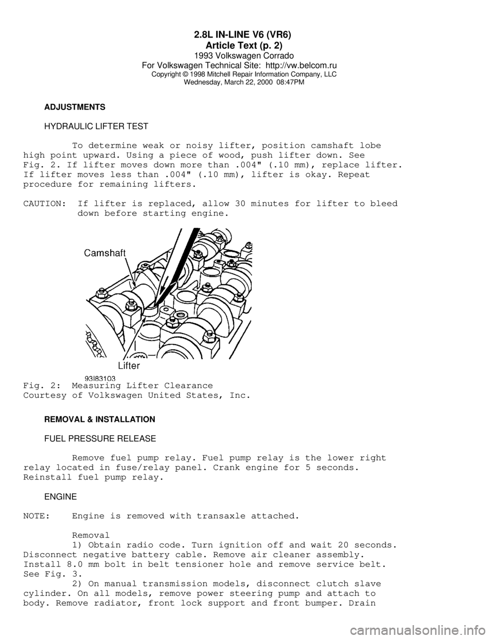
To determine weak or noisy lifter, position camshaft lobe
high point upward. Using a piece of wood, push lifter down. See
Fig. 2. If lifter moves down more than .004" (.10 mm), replace lifter.
If lifter moves less than .004" (.10 mm), lifter is okay. Repeat
procedure for remaining lifters.
CAUTION: If lifter is replaced, allow 30 minutes for lifter to bleed
down before starting engine.Fig. 2: Measuring Lifter Clearance
Courtesy of Volkswagen United States, Inc.
REMOVAL & INSTALLATION
FUEL PRESSURE RELEASE
Remove fuel pump relay. Fuel pump relay is the lower right
relay located in fuse/relay panel. Crank engine for 5 seconds.
Reinstall fuel pump relay.
ENGINE
NOTE: Engine is removed with transaxle attached.
Removal
1) Obtain radio code. Turn ignition off and wait 20 seconds.
Disconnect negative battery cable. Remove air cleaner assembly.
Install 8.0 mm bolt in belt tensioner hole and remove service belt.
See Fig. 3.
2) On manual transmission models, disconnect clutch slave
cylinder. On all models, remove power steering pump and attach to
body. Remove radiator, front lock support and front bumper. Drain
Page 301 of 920

2.8L IN-LINE V6 (VR6)
Article Text (p. 10)
1993 Volkswagen Corrado
For Volkswagen Technical Site: http://vw.belcom.ru
Copyright © 1998 Mitchell Repair Information Company, LLC
Wednesday, March 22, 2000 08:47PM
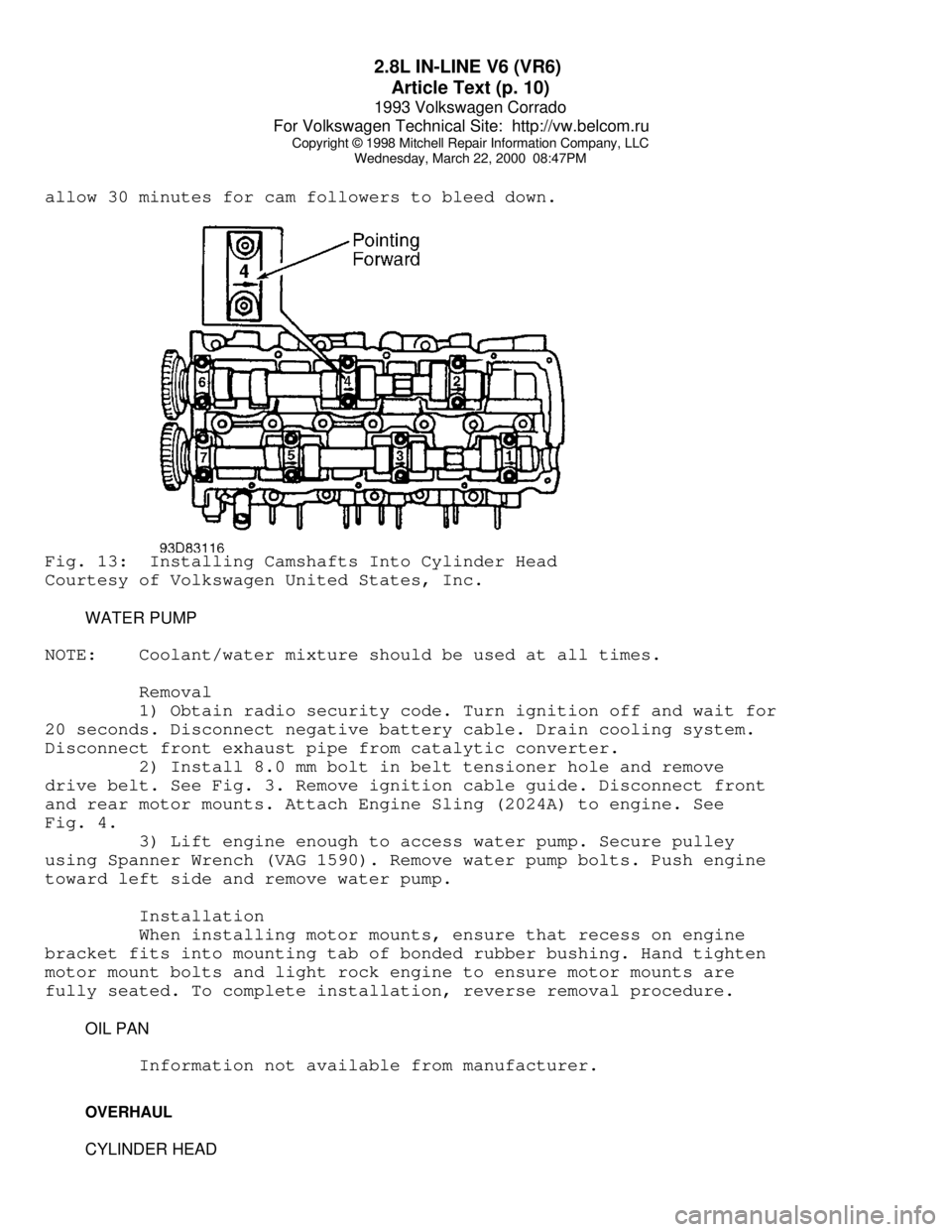
allow 30 minutes for cam followers to bleed down.Fig. 13: Installing Camshafts Into Cylinder Head
Courtesy of Volkswagen United States, Inc.
WATER PUMP
NOTE: Coolant/water mixture should be used at all times.
Removal
1) Obtain radio security code. Turn ignition off and wait for
20 seconds. Disconnect negative battery cable. Drain cooling system.
Disconnect front exhaust pipe from catalytic converter.
2) Install 8.0 mm bolt in belt tensioner hole and remove
drive belt. See Fig. 3. Remove ignition cable guide. Disconnect front
and rear motor mounts. Attach Engine Sling (2024A) to engine. See
Fig. 4.
3) Lift engine enough to access water pump. Secure pulley
using Spanner Wrench (VAG 1590). Remove water pump bolts. Push engine
toward left side and remove water pump.
Installation
When installing motor mounts, ensure that recess on engine
bracket fits into mounting tab of bonded rubber bushing. Hand tighten
motor mount bolts and light rock engine to ensure motor mounts are
fully seated. To complete installation, reverse removal procedure.
OIL PAN
Information not available from manufacturer.
OVERHAUL
CYLINDER HEAD
Page 307 of 920

2.8L IN-LINE V6 (VR6)
Article Text (p. 16)
1993 Volkswagen Corrado
For Volkswagen Technical Site: http://vw.belcom.ru
Copyright © 1998 Mitchell Repair Information Company, LLC
Wednesday, March 22, 2000 08:47PM
TORQUE SPECIFICATIONS
TORQUE SPECIFICATIONS TABLEÄÄÄÄÄÄÄÄÄÄÄÄÄÄÄÄÄÄÄÄÄÄÄÄÄÄÄÄÄÄÄÄÄÄÄÄÄÄÄÄÄÄÄÄÄÄÄÄÄÄÄÄÄÄÄÄÄÄÄÄApplication Ft. Lbs. (N.m)
A/C Bracket-To-Engine Bolt ....................... 22 (30)
Axle Shaft-To-Transaxle Drive Flange Bolt ........ 33 (45)
Camshaft Bearing Cap Bolt ........................ 15 (20)
Camshaft Sprocket Bolt .......................... 74 (100)
Clutch Cover Bolt ................................ 15 (20)
Connecting Rod Bolt ................... 22 (30) + 1/4 Turn
Crankshaft Main Bearing Cap Bolt ...... 22 (30) + 1/2 Turn
Cylinder Head Bolt (1)
Step 1 ......................................... 30 (40)
Step 2 ......................................... 44 (60)
Step 3 ....................... Additional 1/4 (90
ø) Turn
Step 4 ....................... Additional 1/4 (90
ø) Turn
Engine Bracket (Front) ........................... 44 (60)
Engine Bracket (To Body) ......................... 33 (45)
Engine-To-Transaxle 10-mm Bolt ................... 44 (60)
Engine-To-Transaxle 12-mm Bolt ................... 55 (80)
Exhaust Manifold-To-Cylinder Head Bolt & Nut ..... 18 (25)
Exhaust Pipe-To-Catalytic Converter Bolt ......... 18 (25)
Exhaust Pipe-To-Manifold Nut ..................... 30 (40)
Flywheel-To-Crankshaft Bolt ........... 44 (60) + 1/4 Turn
Intake Manifold .................................. 18 (25)
Intermediate Shaft Sprocket Bolt ................ 74 (100)
Oil Pan Bolt ..................................... 15 (20)
Oil Pan Drain Plug ............................... 37 (50)
Oil Pressure Switch .............................. 18 (25)
Oil Pump Cover Long Bolt ............................. (2)
Oil Pump Cover Short Bolt ........................ 18 (25)
Power Steering Pump Bracket Bolt ................. 18 (25)
Pressure Plate Bolt .............................. 15 (20)
Starter Mount Bolt ............................... 18 (25)
Timing Belt Tensioner Nut ........................ 15 (20)
Torque Converter-To-Carrier Plate Bolt ........... 22 (30)
Vibration Damper Bolt .......................... 332 (450)
Water Pump Pulley Bolt ........................... 15 (20)
Water Pump Housing-To-Engine Bolt ................ 15 (20)
INCH Lbs. (N.m)
Fuel Rail Bolt (Lower) ............................ 89 (10)
Timing Belt Idler Bolt ........................... 89 (10)
Valve Cover Retaining Nut ........................ 89 (10)
Water Pump-To-Housing ........................... 115 (13)
(1) - Never reuse cylinder head bolt(s) when servicing.
(2) - Tighten bolt to 89 INCH lbs. (10 N.m).
ÄÄÄÄÄÄÄÄÄÄÄÄÄÄÄÄÄÄÄÄÄÄÄÄÄÄÄÄÄÄÄÄÄÄÄÄÄÄÄÄÄÄÄÄÄÄÄÄÄÄÄÄÄÄÄÄÄÄÄÄ
Page 349 of 920

A/C COMPRESSOR SERVICING
Article Text (p. 13)
1993 Volkswagen Corrado
For Volkswagen Technical Site: http://vw.belcom.ru
Copyright © 1998 Mitchell Repair Information Company, LLC
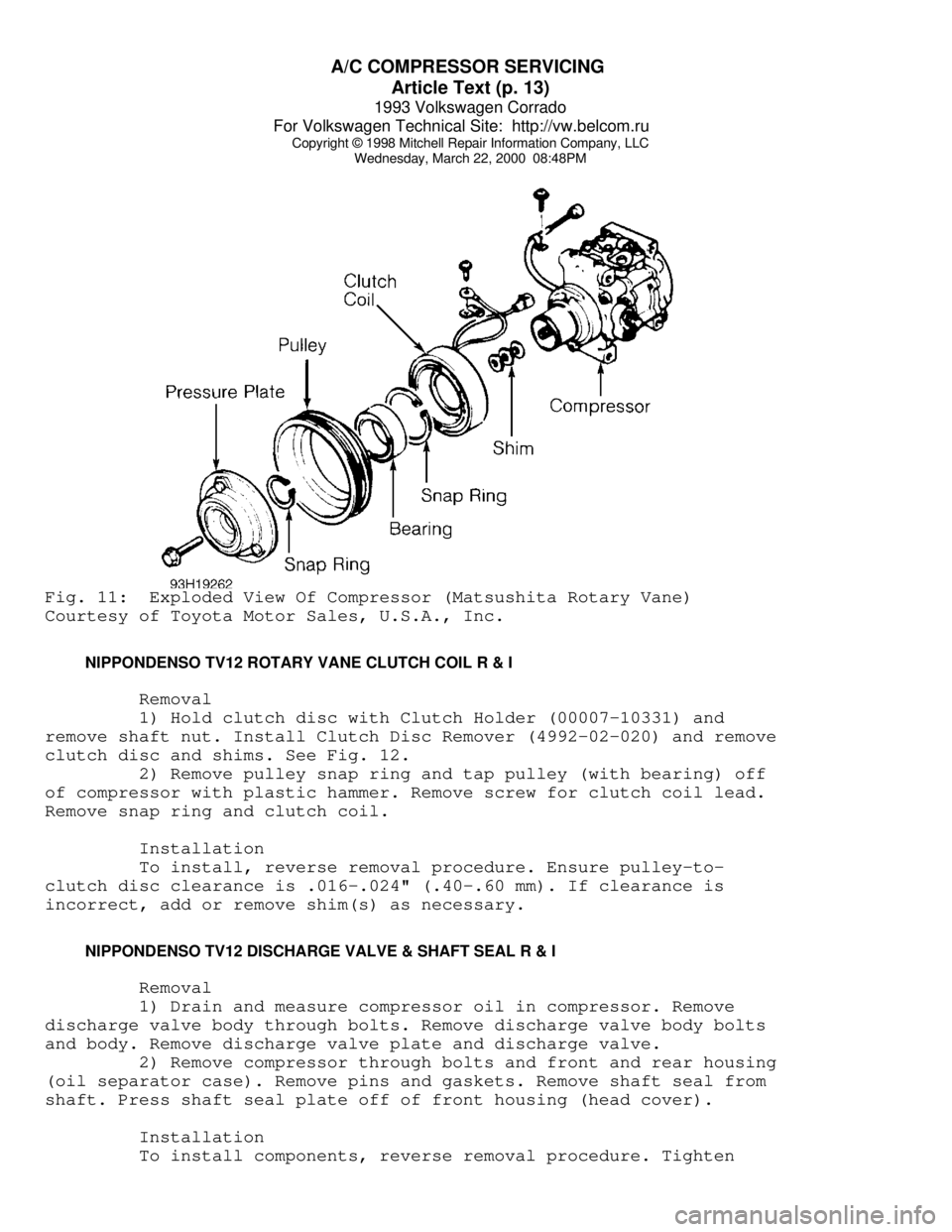
Wednesday, March 22, 2000 08:48PMFig. 11: Exploded View Of Compressor (Matsushita Rotary Vane)
Courtesy of Toyota Motor Sales, U.S.A., Inc.
NIPPONDENSO TV12 ROTARY VANE CLUTCH COIL R & I
Removal
1) Hold clutch disc with Clutch Holder (00007-10331) and
remove shaft nut. Install Clutch Disc Remover (4992-02-020) and remove
clutch disc and shims. See Fig. 12.
2) Remove pulley snap ring and tap pulley (with bearing) off
of compressor with plastic hammer. Remove screw for clutch coil lead.
Remove snap ring and clutch coil.
Installation
To install, reverse removal procedure. Ensure pulley-to-
clutch disc clearance is .016-.024" (.40-.60 mm). If clearance is
incorrect, add or remove shim(s) as necessary.
NIPPONDENSO TV12 DISCHARGE VALVE & SHAFT SEAL R & I
Removal
1) Drain and measure compressor oil in compressor. Remove
discharge valve body through bolts. Remove discharge valve body bolts
and body. Remove discharge valve plate and discharge valve.
2) Remove compressor through bolts and front and rear housing
(oil separator case). Remove pins and gaskets. Remove shaft seal from
shaft. Press shaft seal plate off of front housing (head cover).
Installation
To install components, reverse removal procedure. Tighten
Page 438 of 920

BRAKE SYSTEM
Article Text (p. 7)
1993 Volkswagen Corrado
For Volkswagen Technical Site: http://vw.belcom.ru
Copyright © 1998 Mitchell Repair Information Company, LLC
Wednesday, March 22, 2000 08:57PM
caliper mounting bolts. Depress brake pedal several times to allow
pads to move into operating position. Ensure master cylinder reservoir
fluid level is full.
MASTER CYLINDER
Removal
1) Drain master cylinder reservoir. Remove cover plate (if
equipped). Disconnect brakelines and wiring at master cylinder.
2) On models without power assist servo, disconnect brake
push rod at brake pedal. On models equipped with power assist servo,
remove master cylinder from servo. Be careful to keep any spacers used
on attaching bolts for proper installation.
Installation
To install, reverse removal procedure. Always use NEW "O"
ring between master cylinder and power assist servo. Bleed hydraulic
system.
VACUUM POWER ASSIST SERVO
Removal
Remove master cylinder from power assist servo. Disconnect
brake push rod from brake pedal. Disconnect vacuum hose from servo.
Remove servo from vehicle.
NOTE: Not all vehicles have all components.
Installation
To install, reverse removal procedure. Before attaching brake
push rod to brake pedal, check and adjust push rod length. Always use
NEW damping ring, washer, filter and "O" ring (as equipped). Slots in
damping washer and filter must be offset 180 degrees (if equipped).
Complete installation, and bleed hydraulic system.
OVERHAUL
NOTE: Black staining from piston seal wear may show on caliper
bore walls and piston. This staining is normal. DO NOT
disassemble power assist servo as parts are not available.
Refer to appropriate illustration for caliper and master
cylinder overhaul. See Figs. 6 and 7.
Page 746 of 920

STEERING GEAR - POWER RACK & PINION
Article Text (p. 3)
1993 Volkswagen Corrado
For Volkswagen Technical Site: http://vw.belcom.ru
Copyright © 1998 Mitchell Repair Information Company, LLC
Wednesday, March 22, 2000 09:23PM
Remove rack and pinion assembly. See POWER RACK & PINION
under REMOVAL & INSTALLATION. Loosen lock nut. Turn adjuster bolt
until pinion shaft can be turned by hand without binding. Hold
adjuster bolt in position while tightening lock nut.
REMOVAL & INSTALLATION
POWER STEERING PUMP
Removal
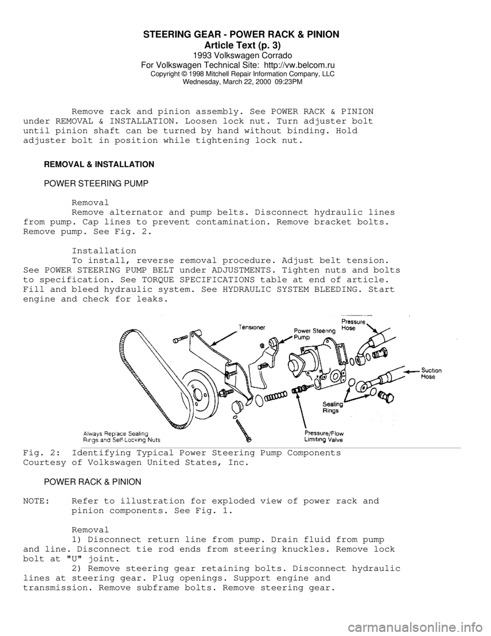
Remove alternator and pump belts. Disconnect hydraulic lines
from pump. Cap lines to prevent contamination. Remove bracket bolts.
Remove pump. See Fig. 2.
Installation
To install, reverse removal procedure. Adjust belt tension.
See POWER STEERING PUMP BELT under ADJUSTMENTS. Tighten nuts and bolts
to specification. See TORQUE SPECIFICATIONS table at end of article.
Fill and bleed hydraulic system. See HYDRAULIC SYSTEM BLEEDING. Start
engine and check for leaks.Fig. 2: Identifying Typical Power Steering Pump Components
Courtesy of Volkswagen United States, Inc.
POWER RACK & PINION
NOTE: Refer to illustration for exploded view of power rack and
pinion components. See Fig. 1.
Removal
1) Disconnect return line from pump. Drain fluid from pump
and line. Disconnect tie rod ends from steering knuckles. Remove lock
bolt at "U" joint.
2) Remove steering gear retaining bolts. Disconnect hydraulic
lines at steering gear. Plug openings. Support engine and
transmission. Remove subframe bolts. Remove steering gear.
Page 789 of 920

TRANSMISSION SERVICING - A/T
Article Text (p. 2)
1993 Volkswagen Corrado
For Volkswagen Technical Site: http://vw.belcom.ru
Copyright © 1998 Mitchell Repair Information Company, LLC
Wednesday, March 22, 2000 09:25PM
EuroVan, Corrado SLC
& Passat ................. 3.2 (3.0) ....... 5.9 (5.6)ÄÄÄÄÄÄÄÄÄÄÄÄÄÄÄÄÄÄÄÄÄÄÄÄÄÄÄÄÄÄÄÄÄÄÄÄÄÄÄÄÄÄÄÄÄÄÄÄÄÄÄÄÄÄÄÄÄÄÄÄFINAL DRIVE REFILL CAPACITIES TABLE
ÄÄÄÄÄÄÄÄÄÄÄÄÄÄÄÄÄÄÄÄÄÄÄÄÄÄÄÄÄÄÄÄÄÄÄÄÄÄÄÄÄÄÄÄÄÄÄÄÄÄÄÄÄÄÄÄÄÄÄÄModel Qts. (L)
All Models ...................................... .8 (.76)
ÄÄÄÄÄÄÄÄÄÄÄÄÄÄÄÄÄÄÄÄÄÄÄÄÄÄÄÄÄÄÄÄÄÄÄÄÄÄÄÄÄÄÄÄÄÄÄÄÄÄÄÄÄÄÄÄÄÄÄÄ DRAINING & REFILLING
1) Remove transmission protection plate (if necessary).
Remove rear pan bolts. Loosen front pan bolts. Carefully lower pan to
drain as much fluid as possible. Remove oil pan. Pour out remaining
fluid.
2) Remove filter. Clean oil pan. Install new filter. Tighten
filter retaining screws to 71 INCH lbs. (8 N.m). Install oil pan with
new gasket. Tighten oil pan bolts to 89 INCH lbs. (10 N.m).
3) Install protection plate if it was removed. Tighten bolts
to 18 ft. lbs. (25 N.m). Add 3.2 qts. (3.0L) transmission fluid. Check
fluid level. Add if necessary.
ADJUSTMENTS
SELECTOR LEVER CABLE
Corrado SLC, EuroVan & Passat
Set transmission selector to Park. Loosen screw at gear lever
shaft. Set gear lever in Park. Ensure detent engages parking lock.
Tighten screw to 15 ft. lbs. (20 N.m) on Corrado SLC and EuroVan.
Tighten screw to 18 ft. lbs. (25 N.m) on Passat.
NEUTRAL SAFETY SWITCH
Neutral safety switch is located in shift console. Remove
console cover. Adjust switch so that engine starts in Park and Neutral
positions only.
END OF ARTICLE