1993 VOLKSWAGEN CORRADO gas type
[x] Cancel search: gas typePage 12 of 920

* A/C-HEATER SYSTEM UNIFORM INSPECTION GUIDELINES *
Article Text (p. 10)
1993 Volkswagen Corrado
For Volkswagen Technical Site: http://vw.belcom.ru
Copyright © 1998 Mitchell Repair Information Company, LLC
Wednesday, March 22, 2000 08:22PM
³ ³ components as necessary.
³ ³ Discoloration of oil does not
³ ³ necessarily indicate a system
³ ³ problem.
ÄÄÄÄÄÄÄÄÄÄÄÄÄÁÄÄÄÄÄÄÄÄÄÄÄÄÄÄÄÄÄÄÄÄÄÁÄÄÄÄÄÄÄÄÄÄÄÄÄÄÄÄÄÄÄÄÄÄÄÄÄÄÄÄÄÄÄÄÄÄ REFRIGERANT
REFRIGERANT
ÄÄÄÄÄÄÄÄÄÄÄÄÄÄÄÄÄÄÄÄÄÄÄÄÄÄÄÄÄÄÄÄÄÄÂÄÄÄÄÄÄÄÄÄÄÄÄÄÄÄÄÄÄÄÄÄÄÄÄÄÄÄÄÄÄÄÄÄÄÄCondition
³ Procedure
ÄÄÄÄÄÄÄÄÄÄÄÄÄÄÄÄÄÄÄÄÄÄÄÄÄÄÄÄÄÄÄÄÄÄÅÄÄÄÄÄÄÄÄÄÄÄÄÄÄÄÄÄÄÄÄÄÄÄÄÄÄÄÄÄÄÄÄÄÄÄOvercharge/undercharge
³ Require service to manufacturer's
³ specifications.
ÄÄÄÄÄÄÄÄÄÄÄÄÄÄÄÄÄÄÄÄÄÄÄÄÄÄÄÄÄÄÄÄÄÄÅÄÄÄÄÄÄÄÄÄÄÄÄÄÄÄÄÄÄÄÄÄÄÄÄÄÄÄÄÄÄÄÄÄÄÄCross-contamination
³
ÄÄÄÄÄÄÄÄÄÄÄÄÄÄÄÄÄÄÄÄÄÄÄÄÄÄÄÄÄÄÄÄÄÄ´ Require service following
Different types of refrigerants
³ manufacturer's procedures and
in the same system
³ specifications.
ÄÄÄÄÄÄÄÄÄÄÄÄÄÄÄÄÄÄÄÄÄÄÄÄÄÄÄÄÄÄÄÄÄÄ´Incompatible refrigerants mixed
³together
³
ÄÄÄÄÄÄÄÄÄÄÄÄÄÄÄÄÄÄÄÄÄÄÄÄÄÄÄÄÄÄÄÄÄÄÁÄÄÄÄÄÄÄÄÄÄÄÄÄÄÄÄÄÄÄÄÄÄÄÄÄÄÄÄÄÄÄÄÄÄÄ AIR DISTRIBUTION
PLENUM/EVAPORATOR CASE/HEATER CASE
ÄÄÄÄÄÄÄÄÄÄÄÄÄÂÄÄÄÄÄÄÄÄÄÄÄÄÄÄÄÄÄÄÄÄÄÄÄÂÄÄÄÄÄÄÄÄÄÄÄÄÄÄÄÄÄÄÄÄÄÄÄÄÄÄÄÄÄÄÄÄCondition
³ Procedure ³ Note
ÄÄÄÄÄÄÄÄÄÄÄÄÄÅÄÄÄÄÄÄÄÄÄÄÄÄÄÄÄÄÄÄÄÄÄÄÄÅÄÄÄÄÄÄÄÄÄÄÄÄÄÄÄÄÄÄÄÄÄÄÄÄÄÄÄÄÄÄÄÄCracked
³ Suggest repair or ³
³ replacement. ³
ÄÄÄÄÄÄÄÄÄÄÄÄÄÅÄÄÄÄÄÄÄÄÄÄÄÄÄÄÄÄÄÄÄÄÄÄÄÅÄÄÄÄÄÄÄÄÄÄÄÄÄÄÄÄÄÄÄÄÄÄÄÄÄÄÄÄÄÄÄÄAir leaks
³ Require repair or ³
³ replacement ³
ÄÄÄÄÄÄÄÄÄÄÄÄÄÅÄÄÄÄÄÄÄÄÄÄÄÄÄÄÄÄÄÄÄÄÄÄÄÅÄÄÄÄÄÄÄÄÄÄÄÄÄÄÄÄÄÄÄÄÄÄÄÄÄÄÄÄÄÄÄÄRestricted
³ Suggest cleaning, ³
³ repair or replacement.³
ÄÄÄÄÄÄÄÄÄÄÄÄÄÅÄÄÄÄÄÄÄÄÄÄÄÄÄÄÄÄÄÄÄÄÄÄÄÅÄÄÄÄÄÄÄÄÄÄÄÄÄÄÄÄÄÄÄÄÄÄÄÄÄÄÄÄÄÄÄÄOdor
³ Further inspection ³ Identify source. Suggest
³ required. ³ cleaning or repair.
ÄÄÄÄÄÄÄÄÄÄÄÄÄÅÄÄÄÄÄÄÄÄÄÄÄÄÄÄÄÄÄÄÄÄÄÄÄÅÄÄÄÄÄÄÄÄÄÄÄÄÄÄÄÄÄÄÄÄÄÄÄÄÄÄÄÄÄÄÄÄNoisy
³ Further inspection ³ Identify source. Suggest
³ required. ³ cleaning or repair.
ÄÄÄÄÄÄÄÄÄÄÄÄÄÅÄÄÄÄÄÄÄÄÄÄÄÄÄÄÄÄÄÄÄÄÄÄÄÅÄÄÄÄÄÄÄÄÄÄÄÄÄÄÄÄÄÄÄÄÄÄÄÄÄÄÄÄÄÄÄÄCold water
³ Further inspection ³ Determine source of leak. Leak
leak in
³ required. ³ may be caused due to restricted
passenger
³ ³ drain tube, cracked evaporator
compartment
³ ³ case, leaking seal or gasket.
³ ³ Require repair or replacement.
ÄÄÄÄÄÄÄÄÄÄÄÄÄÁÄÄÄÄÄÄÄÄÄÄÄÄÄÄÄÄÄÄÄÄÄÄÄÁÄÄÄÄÄÄÄÄÄÄÄÄÄÄÄÄÄÄÄÄÄÄÄÄÄÄÄÄÄÄÄÄ
Page 111 of 920

* ENGINE SYSTEMS UNIFORM INSPECTION GUIDELINES *
Article Text (p. 14)
1993 Volkswagen Corrado
For Volkswagen Technical Site: http://vw.belcom.ru
Copyright © 1998 Mitchell Repair Information Company, LLC
Wednesday, March 22, 2000 08:41PM
Leaking ³ Require replacement.
ÄÄÄÄÄÄÄÄÄÄÄÄÄÄÄÄÄÄÄÄÄÄÅÄÄÄÄÄÄÄÄÄÄÄÄÄÄÄÄÄÄÄÄÄÄÄÄÄÄÄÄÄÄÄÄÄÄÄÄÄÄÄÄÄÄÄÄÄÄÄImproper type
³ Suggest replacement.
ÄÄÄÄÄÄÄÄÄÄÄÄÄÄÄÄÄÄÄÄÄÄÁÄÄÄÄÄÄÄÄÄÄÄÄÄÄÄÄÄÄÄÄÄÄÄÄÄÄÄÄÄÄÄÄÄÄÄÄÄÄÄÄÄÄÄÄÄÄÄ AIR INDUCTION SYSTEM
AIR DUCT/TUBES
ÄÄÄÄÄÄÄÄÄÄÄÄÄÄÄÄÄÄÄÄÄÄÂÄÄÄÄÄÄÄÄÄÄÄÄÄÄÄÄÄÄÄÄÄÄÄÄÄÄÄÄÄÄÄÄÄÄÄÄÄÄÄÄÄÄÄÄÄÄÄCondition
³ Procedure
ÄÄÄÄÄÄÄÄÄÄÄÄÄÄÄÄÄÄÄÄÄÄÅÄÄÄÄÄÄÄÄÄÄÄÄÄÄÄÄÄÄÄÄÄÄÄÄÄÄÄÄÄÄÄÄÄÄÄÄÄÄÄÄÄÄÄÄÄÄÄMissing
³ Require replacement.
ÄÄÄÄÄÄÄÄÄÄÄÄÄÄÄÄÄÄÄÄÄÄÅÄÄÄÄÄÄÄÄÄÄÄÄÄÄÄÄÄÄÄÄÄÄÄÄÄÄÄÄÄÄÄÄÄÄÄÄÄÄÄÄÄÄÄÄÄÄÄDamaged
³ Suggest repair or replacement.
ÄÄÄÄÄÄÄÄÄÄÄÄÄÄÄÄÄÄÄÄÄÄÅÄÄÄÄÄÄÄÄÄÄÄÄÄÄÄÄÄÄÄÄÄÄÄÄÄÄÄÄÄÄÄÄÄÄÄÄÄÄÄÄÄÄÄÄÄÄÄLeaking
³ Require repair or replacement.
ÄÄÄÄÄÄÄÄÄÄÄÄÄÄÄÄÄÄÄÄÄÄÁÄÄÄÄÄÄÄÄÄÄÄÄÄÄÄÄÄÄÄÄÄÄÄÄÄÄÄÄÄÄÄÄÄÄÄÄÄÄÄÄÄÄÄÄÄÄÄAIR FILTER HOUSING/GASKETS
ÄÄÄÄÄÄÄÄÄÄÄÄÄÄÄÄÄÄÄÄÄÄÄÄÄÄÄÄÄÄÄÄÄÄÂÄÄÄÄÄÄÄÄÄÄÄÄÄÄÄÄÄÄÄÄÄÄÄÄÄÄÄÄÄÄÄÄÄÄÄCondition
³ Procedure
ÄÄÄÄÄÄÄÄÄÄÄÄÄÄÄÄÄÄÄÄÄÄÄÄÄÄÄÄÄÄÄÄÄÄÅÄÄÄÄÄÄÄÄÄÄÄÄÄÄÄÄÄÄÄÄÄÄÄÄÄÄÄÄÄÄÄÄÄÄÄMissing
³ Require replacement.
ÄÄÄÄÄÄÄÄÄÄÄÄÄÄÄÄÄÄÄÄÄÄÄÄÄÄÄÄÄÄÄÄÄÄÅÄÄÄÄÄÄÄÄÄÄÄÄÄÄÄÄÄÄÄÄÄÄÄÄÄÄÄÄÄÄÄÄÄÄÄDamaged
³ Suggest repair or replacement.
ÄÄÄÄÄÄÄÄÄÄÄÄÄÄÄÄÄÄÄÄÄÄÄÄÄÄÄÄÄÄÄÄÄÄÅÄÄÄÄÄÄÄÄÄÄÄÄÄÄÄÄÄÄÄÄÄÄÄÄÄÄÄÄÄÄÄÄÄÄÄLeaking
³ Require repair or replacement.
ÄÄÄÄÄÄÄÄÄÄÄÄÄÄÄÄÄÄÄÄÄÄÄÄÄÄÄÄÄÄÄÄÄÄÅÄÄÄÄÄÄÄÄÄÄÄÄÄÄÄÄÄÄÄÄÄÄÄÄÄÄÄÄÄÄÄÄÄÄÄMissing/damaged mounting hardware
³ Require repair or replacement of
³ hardware.
ÄÄÄÄÄÄÄÄÄÄÄÄÄÄÄÄÄÄÄÄÄÄÄÄÄÄÄÄÄÄÄÄÄÄÁÄÄÄÄÄÄÄÄÄÄÄÄÄÄÄÄÄÄÄÄÄÄÄÄÄÄÄÄÄÄÄÄÄÄÄAIR FILTER ELEMENT
ÄÄÄÄÄÄÄÄÄÄÄÄÄÄÄÄÄÄÄÄÄÄÄÂÄÄÄÄÄÄÄÄÄÄÄÄÄÄÄÄÄÄÄÄÄÄÄÄÄÄÄÄÄÄÄÄÄÄÄÄÄÄÄÄÄÄÄÄÄÄCondition
³ Procedure
ÄÄÄÄÄÄÄÄÄÄÄÄÄÄÄÄÄÄÄÄÄÄÄÅÄÄÄÄÄÄÄÄÄÄÄÄÄÄÄÄÄÄÄÄÄÄÄÄÄÄÄÄÄÄÄÄÄÄÄÄÄÄÄÄÄÄÄÄÄÄMissing
³ Require replacement.
ÄÄÄÄÄÄÄÄÄÄÄÄÄÄÄÄÄÄÄÄÄÄÄÅÄÄÄÄÄÄÄÄÄÄÄÄÄÄÄÄÄÄÄÄÄÄÄÄÄÄÄÄÄÄÄÄÄÄÄÄÄÄÄÄÄÄÄÄÄÄDamaged
³ Suggest replacement.
ÄÄÄÄÄÄÄÄÄÄÄÄÄÄÄÄÄÄÄÄÄÄÄÅÄÄÄÄÄÄÄÄÄÄÄÄÄÄÄÄÄÄÄÄÄÄÄÄÄÄÄÄÄÄÄÄÄÄÄÄÄÄÄÄÄÄÄÄÄÄRestricted
³ Suggest replacement.
ÄÄÄÄÄÄÄÄÄÄÄÄÄÄÄÄÄÄÄÄÄÄÄÅÄÄÄÄÄÄÄÄÄÄÄÄÄÄÄÄÄÄÄÄÄÄÄÄÄÄÄÄÄÄÄÄÄÄÄÄÄÄÄÄÄÄÄÄÄÄMaintenance intervals
³ Suggest replacement to comply with vehicle's
³ OEM recommended service intervals.
ÄÄÄÄÄÄÄÄÄÄÄÄÄÄÄÄÄÄÄÄÄÄÄÁÄÄÄÄÄÄÄÄÄÄÄÄÄÄÄÄÄÄÄÄÄÄÄÄÄÄÄÄÄÄÄÄÄÄÄÄÄÄÄÄÄÄÄÄÄÄPCV BREATHER ELEMENT
ÄÄÄÄÄÄÄÄÄÄÄÄÄÄÄÄÄÄÄÄÄÄÄÂÄÄÄÄÄÄÄÄÄÄÄÄÄÄÄÄÄÄÄÄÄÄÄÄÄÄÄÄÄÄÄÄÄÄÄÄÄÄÄÄÄÄÄÄÄÄCondition
³ Procedure
ÄÄÄÄÄÄÄÄÄÄÄÄÄÄÄÄÄÄÄÄÄÄÄÅÄÄÄÄÄÄÄÄÄÄÄÄÄÄÄÄÄÄÄÄÄÄÄÄÄÄÄÄÄÄÄÄÄÄÄÄÄÄÄÄÄÄÄÄÄÄMissing
³ Require replacement.
ÄÄÄÄÄÄÄÄÄÄÄÄÄÄÄÄÄÄÄÄÄÄÄÅÄÄÄÄÄÄÄÄÄÄÄÄÄÄÄÄÄÄÄÄÄÄÄÄÄÄÄÄÄÄÄÄÄÄÄÄÄÄÄÄÄÄÄÄÄÄ
Page 140 of 920

* EXHAUST SYSTEM UNIFORM INSPECTION GUIDELINES *
Article Text (p. 5)
1993 Volkswagen Corrado
For Volkswagen Technical Site: http://vw.belcom.ru
Copyright © 1998 Mitchell Repair Information Company, LLC
Wednesday, March 22, 2000 08:41PM
CATALYTIC CONVERTERS
CAUTION: Before working on an exhaust system, review EPA regulations
on removing and replacing catalytic converters.
NOTE: Any time a converter has failed, further diagnosis is
required to determine the reason(s) for converter failure.
Advise customer of cause(s).
CATALYTIC CONVERTERSÄÄÄÄÄÄÄÄÄÄÄÄÄÄÄÄÄÄÄÄÄÄÄÄÄÄÄÄÂÄÄÄÄÄÄÂÄÄÄÄÄÄÄÄÄÄÄÄÄÄÄÄÄÄÄÄÄÄÄÄÄÄÄÄÄÄÄÄÄÄCondition
³ Code ³ Procedure
ÄÄÄÄÄÄÄÄÄÄÄÄÄÄÄÄÄÄÄÄÄÄÄÄÄÄÄÄÅÄÄÄÄÄÄÅÄÄÄÄÄÄÄÄÄÄÄÄÄÄÄÄÄÄÄÄÄÄÄÄÄÄÄÄÄÄÄÄÄÄAir injection tube broken
³ A ³
ÄÄÄÄÄÄÄÄÄÄÄÄÄÄÄÄÄÄÄÄÄÄÄÄÄÄÄÄÅÄÄÄÄÄÄ´Air injection tube burnt
³ A ³
ÄÄÄÄÄÄÄÄÄÄÄÄÄÄÄÄÄÄÄÄÄÄÄÄÄÄÄÄÅÄÄÄÄÄÄ´Air injection tube damaged
³ B ³
ÄÄÄÄÄÄÄÄÄÄÄÄÄÄÄÄÄÄÄÄÄÄÄÄÄÄÄÄÅÄÄÄÄÄÄ´Air injection tube leaking
³ A ³
ÄÄÄÄÄÄÄÄÄÄÄÄÄÄÄÄÄÄÄÄÄÄÄÄÄÄÄÄÅÄÄÄÄÄÄ´Air injection tube loose
³ A ³ Require repair or replacement of
ÄÄÄÄÄÄÄÄÄÄÄÄÄÄÄÄÄÄÄÄÄÄÄÄÄÄÄÄÅÄÄÄÄÄÄ´ injection tube or replacement of
Air injection tube
³ A ³ catalytic converter.
restricted
³ ³
ÄÄÄÄÄÄÄÄÄÄÄÄÄÄÄÄÄÄÄÄÄÄÄÄÄÄÄÄÅÄÄÄÄÄÄ´Air injection tube threads
³ B ³ damaged
³ ³
ÄÄÄÄÄÄÄÄÄÄÄÄÄÄÄÄÄÄÄÄÄÄÄÄÄÄÄÄÅÄÄÄÄÄÄ´Air injection tube threads
³ A ³ stripped (threads missing)
³ ³
ÄÄÄÄÄÄÄÄÄÄÄÄÄÄÄÄÄÄÄÄÄÄÄÄÄÄÄÄÅÄÄÄÄÄÄÅÄÄÄÄÄÄÄÄÄÄÄÄÄÄÄÄÄÄÄÄÄÄÄÄÄÄÄÄÄÄÄÄÄÄBody cracked
³ B ³
ÄÄÄÄÄÄÄÄÄÄÄÄÄÄÄÄÄÄÄÄÄÄÄÄÄÄÄÄÅÄÄÄÄÄÄ´Converter empty
³ A ³ Require repair or replacement.
ÄÄÄÄÄÄÄÄÄÄÄÄÄÄÄÄÄÄÄÄÄÄÄÄÄÄÄÄÅÄÄÄÄÄÄ´Converter fill plug missing
³ C ³
ÄÄÄÄÄÄÄÄÄÄÄÄÄÄÄÄÄÄÄÄÄÄÄÄÄÄÄÄÅÄÄÄÄÄÄÅÄÄÄÄÄÄÄÄÄÄÄÄÄÄÄÄÄÄÄÄÄÄÄÄÄÄÄÄÄÄÄÄÄÄConverter missing
³ C ³ Require replacement.
ÄÄÄÄÄÄÄÄÄÄÄÄÄÄÄÄÄÄÄÄÄÄÄÄÄÄÄÄÅÄÄÄÄÄÄÅÄÄÄÄÄÄÄÄÄÄÄÄÄÄÄÄÄÄÄÄÄÄÄÄÄÄÄÄÄÄÄÄÄÄExhaust gases leaking
³ A ³ Require repair or replacement.
ÄÄÄÄÄÄÄÄÄÄÄÄÄÄÄÄÄÄÄÄÄÄÄÄÄÄÄÄÅÄÄÄÄÄÄÅÄÄÄÄÄÄÄÄÄÄÄÄÄÄÄÄÄÄÄÄÄÄÄÄÄÄÄÄÄÄÄÄÄÄFlanges leaking
³ A ³ Require repair or replacement of
³ ³ flanges.
ÄÄÄÄÄÄÄÄÄÄÄÄÄÄÄÄÄÄÄÄÄÄÄÄÄÄÄÄÅÄÄÄÄÄÄÅÄÄÄÄÄÄÄÄÄÄÄÄÄÄÄÄÄÄÄÄÄÄÄÄÄÄÄÄÄÄÄÄÄÄInlet pipes cracked
³ B ³ Require repair or replacement.
ÄÄÄÄÄÄÄÄÄÄÄÄÄÄÄÄÄÄÄÄÄÄÄÄÄÄÄÄÅÄÄÄÄÄÄÅÄÄÄÄÄÄÄÄÄÄÄÄÄÄÄÄÄÄÄÄÄÄÄÄÄÄÄÄÄÄÄÄÄÄInternal rattle (except
³ B,2 ³ Further inspection required.
pellet-type)
³ ³ See note (1) below.
ÄÄÄÄÄÄÄÄÄÄÄÄÄÄÄÄÄÄÄÄÄÄÄÄÄÄÄÄÅÄÄÄÄÄÄÅÄÄÄÄÄÄÄÄÄÄÄÄÄÄÄÄÄÄÄÄÄÄÄÄÄÄÄÄÄÄÄÄÄÄMounting brackets that are
³ A ³ Require repair or replacement.
Page 296 of 920

2.8L IN-LINE V6 (VR6)
Article Text (p. 5)
1993 Volkswagen Corrado
For Volkswagen Technical Site: http://vw.belcom.ru
Copyright © 1998 Mitchell Repair Information Company, LLC
Wednesday, March 22, 2000 08:47PM
Inspection
Thoroughly clean all gasket mating surfaces. Check cylinder
head for warpage. Maximum warpage is .004" (.10 mm). Check minimum
cylinder head height and replace cylinder head (if necessary).
NOTE: DO NOT reuse antifreeze after replacing cylinder block,
cylinder head, head gasket, radiator and/or heater core. The
following INSTALLATION information is all that is available
from manufacturer.
Installation
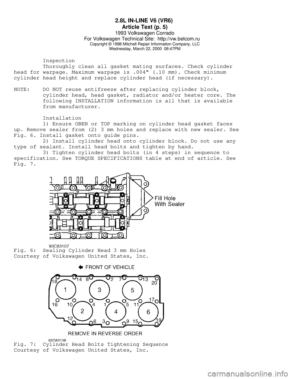
1) Ensure OBEN or TOP marking on cylinder head gasket faces
up. Remove sealer from (2) 3 mm holes and replace with new sealer. See
Fig. 6. Install gasket onto guide pins.
2) Install cylinder head onto cylinder block. Do not use any
type of sealant. Install head bolts and tighten by hand.
3) Tighten cylinder head bolts (in 4 steps) in sequence to
specification. See TORQUE SPECIFICATIONS table at end of article. See
Fig. 7.Fig. 6: Sealing Cylinder Head 3 mm Holes
Courtesy of Volkswagen United States, Inc.Fig. 7: Cylinder Head Bolts Tightening Sequence
Courtesy of Volkswagen United States, Inc.
Page 516 of 920

EMISSION CONTROL VISUAL INSPECTION PROCEDURES
Article Text (p. 2)
1993 Volkswagen Corrado
For Volkswagen Technical Site: http://vw.belcom.ru
Copyright © 1998 Mitchell Repair Information Company, LLC
Wednesday, March 22, 2000 09:09PM
NOTE: The following emission control visual inspection procedures
should be used as a guide only. When performing a visual
inspection, always follow your state's recommended
inspection procedures.
A visual inspection is made to determine if any required
emission control devices are missing, modified or disconnected.
Missing, modified or disconnected systems must be made fully
operational before a vehicle can be certified.
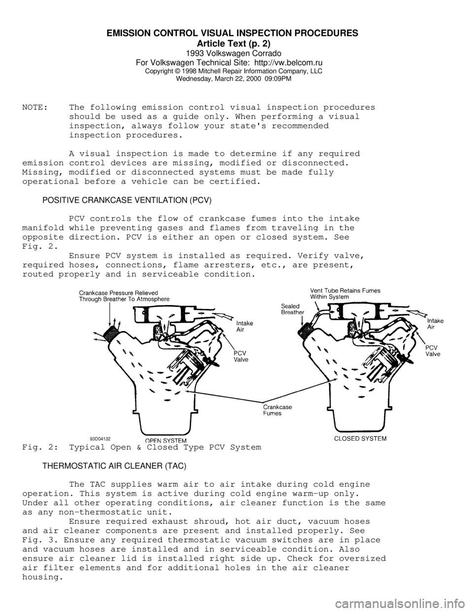
POSITIVE CRANKCASE VENTILATION (PCV)
PCV controls the flow of crankcase fumes into the intake
manifold while preventing gases and flames from traveling in the
opposite direction. PCV is either an open or closed system. See
Fig. 2.
Ensure PCV system is installed as required. Verify valve,
required hoses, connections, flame arresters, etc., are present,
routed properly and in serviceable condition.Fig. 2: Typical Open & Closed Type PCV System
THERMOSTATIC AIR CLEANER (TAC)
The TAC supplies warm air to air intake during cold engine
operation. This system is active during cold engine warm-up only.
Under all other operating conditions, air cleaner function is the same
as any non-thermostatic unit.
Ensure required exhaust shroud, hot air duct, vacuum hoses
and air cleaner components are present and installed properly. See
Fig. 3. Ensure any required thermostatic vacuum switches are in place
and vacuum hoses are installed and in serviceable condition. Also
ensure air cleaner lid is installed right side up. Check for oversized
air filter elements and for additional holes in the air cleaner
housing.
Page 519 of 920

EMISSION CONTROL VISUAL INSPECTION PROCEDURES
Article Text (p. 5)
1993 Volkswagen Corrado
For Volkswagen Technical Site: http://vw.belcom.ru
Copyright © 1998 Mitchell Repair Information Company, LLC
Wednesday, March 22, 2000 09:09PM
Visually check for presence of catalytic converter(s). Also
check for presence of any required air supply system for the oxidizing
section of the converter. Check for external damage such as severe
dents, removed or damaged heat shields, etc. Check for pellets or
pieces of converter in the tailpipe.
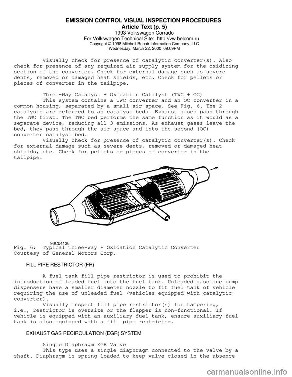
Three-Way Catalyst + Oxidation Catalyst (TWC + OC)
This system contains a TWC converter and an OC converter in a
common housing, separated by a small air space. See Fig. 6. The 2
catalysts are referred to as catalyst beds. Exhaust gases pass through
the TWC first. The TWC bed performs the same function as it would as a
separate device, reducing all 3 emissions. As exhaust gases leave the
bed, they pass through the air space and into the second (OC)
converter catalyst bed.
Visually check for presence of catalytic converter(s). Check
for external damage such as severe dents, removed or damaged heat
shields, etc. Check for pellets or pieces of converter in the
tailpipe.Fig. 6: Typical Three-Way + Oxidation Catalytic Converter
Courtesy of General Motors Corp.
FILL PIPE RESTRICTOR (FR)
A fuel tank fill pipe restrictor is used to prohibit the
introduction of leaded fuel into the fuel tank. Unleaded gasoline pump
dispensers have a smaller diameter nozzle to fit fuel tank of vehicle
requiring the use of unleaded fuel (vehicles equipped with catalytic
converter).
Visually inspect fill pipe restrictor(s) for tampering,
i.e., restrictor is oversize or the flapper is non-functional. If
vehicle is equipped with an auxiliary fuel tank, ensure auxiliary fuel
tank is also equipped with a fill pipe restrictor.
EXHAUST GAS RECIRCULATION (EGR) SYSTEM
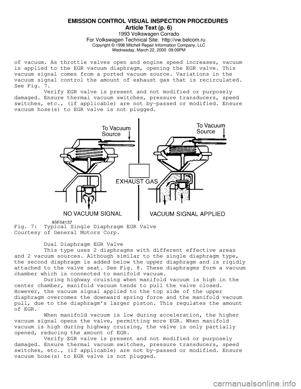
Single Diaphragm EGR Valve
This type uses a single diaphragm connected to the valve by a
shaft. Diaphragm is spring-loaded to keep valve closed in the absence
Page 520 of 920

EMISSION CONTROL VISUAL INSPECTION PROCEDURES
Article Text (p. 6)
1993 Volkswagen Corrado
For Volkswagen Technical Site: http://vw.belcom.ru
Copyright © 1998 Mitchell Repair Information Company, LLC
Wednesday, March 22, 2000 09:09PM
of vacuum. As throttle valves open and engine speed increases, vacuum
is applied to the EGR vacuum diaphragm, opening the EGR valve. This
vacuum signal comes from a ported vacuum source. Variations in the
vacuum signal control the amount of exhaust gas that is recirculated.
See Fig. 7.
Verify EGR valve is present and not modified or purposely
damaged. Ensure thermal vacuum switches, pressure transducers, speed
switches, etc., (if applicable) are not by-passed or modified. Ensure
vacuum hose(s) to EGR valve is not plugged.Fig. 7: Typical Single Diaphragm EGR Valve
Courtesy of General Motors Corp.
Dual Diaphragm EGR Valve
This type uses 2 diaphragms with different effective areas
and 2 vacuum sources. Although similar to the single diaphragm type,
the second diaphragm is added below the upper diaphragm and is rigidly
attached to the valve seat. See Fig. 8. These diaphragms form a vacuum
chamber which is connected to manifold vacuum.
During highway cruising when manifold vacuum is high in the
center chamber, manifold vacuum tends to pull the valve closed.
However, the vacuum signal applied to the top side of the upper
diaphragm overcomes the downward spring force and the manifold vacuum
pull, due to the diaphragm's larger piston. This regulates the amount
of EGR.
When manifold vacuum is low during acceleration, the higher
vacuum signal opens the valve, permitting more EGR. When manifold
vacuum is high during highway cruising, the valve is only partially
opened, reducing the amount of EGR.
Verify EGR valve is present and not modified or purposely
damaged. Ensure thermal vacuum switches, pressure transducers, speed
switches, etc., (if applicable) are not by-passed or modified. Ensure
vacuum hose(s) to EGR valve is not plugged.
Page 527 of 920

EMISSION CONTROL VISUAL INSPECTION PROCEDURES
Article Text (p. 13)
1993 Volkswagen Corrado
For Volkswagen Technical Site: http://vw.belcom.ru
Copyright © 1998 Mitchell Repair Information Company, LLC
Wednesday, March 22, 2000 09:09PM
OXYGEN SENSOR (O2)
The O2 sensor is mounted in the exhaust system where it
monitors oxygen content of exhaust gases. Some vehicles may use 2 O2
sensors. The O2 sensor produces a voltage signal which is proportional
to exhaust gas oxygen concentration (0-3%) compared to outside oxygen
(20-21%). This voltage signal is low (about .1 volt) when a lean
mixture is present and high (1.0 volt) when a rich mixture is present.
As ECM compensates for a lean or rich condition, this
voltage signal constantly fluctuates between high and low, crossing a
reference voltage supplied by the ECM on the O2 signal line. This is
referred to as cross counts. A problem in the O2 sensor circuit should
set a related trouble code.
COMPUTERIZED ENGINE CONTROLS (CEC)
The CEC system monitors and controls a variety of
engine/vehicle functions. The CEC system is primarily an emission
control system designed to maintain a 14.7:1 air/fuel ratio under most
operating conditions. When the ideal air/fuel ratio is maintained, the
catalytic converter can control oxides of nitrogen (NOx), hydrocarbon
(HC) and carbon monoxide (CO) emissions.
The CEC system consists of the following sub-systems:
Electronic Control Module (ECM), input devices (sensors and switches)
and output signals.
EARLY FUEL EVAPORATION (EFE)
The EFE valve is actuated by either a vacuum actuator or a
bimetal spring (heat-riser type). The EFE valve is closed when engine
is cold. The closed valve restricts exhaust gas flow from the exhaust
manifold. This forces part of the exhaust gas to flow up through a
passage below the carburetor. As the exhaust gas quickly warms the
intake mixture, distribution is improved. This results in better cold
engine driveability, shorter choke periods and lower emissions.
Ensure EFE valve in exhaust manifold is not frozen or rusted
in a fixed position. On vacuum-actuated EFE system, check EFE thermal
vacuum valve and check valve(s). Also check for proper vacuum hose
routing. See Fig. 15.