1993 FORD MONDEO coolant
[x] Cancel search: coolantPage 107 of 279
into the inlet ports, just above the inlet valves,
by four fuel injectors. The system also
includes features such as the flushing of fresh
(ie, cold) fuel around each injector on start-up,
thus improving hot starts.
The amount of fuel supplied by the injectors
is precisely controlled by an Electronic
Control Unit (ECU). The ECU uses the signals
derived from the engine speed/crankshaft
position sensor and the camshaft position
sensor, to trigger each injector separately in
cylinder firing order (sequential injection), with
benefits in terms of better fuel economy and
lower exhaust emissions.
Air induction system
The air system consists of an air filter
housing, an air mass meter, an intake
resonator and plenum chamber, and a throttle
housing. The air mass meter is an information-
gathering device for the ECU; it uses a “hot-
wire” system to send the ECU a constantly-
varying (analogue) voltage signal
corresponding to the volume of air passing
into the engine. Another sensor in the air mass
meter measures intake air temperature. The
ECU uses these signals to calculate the mass
of air entering the engine.
The throttle valve inside the throttle housing
is controlled by the driver, through the
accelerator pedal. As the valve opens, the
amount of air that can pass through the
system increases. The throttle potentiometer
opens further, the air mass meter’s signal
alters, and the ECU opens each injector for a
longer duration, to increase the amount of fuel
delivered to the inlet ports.
Electronic control system
The ECU controls the fuel injection system,
as well as the other sub-systems which make
up the entire engine management system. It
receives signals from a number of information
sensors, which monitor such variables as
intake air mass and temperature, coolant
temperature, engine speed and position,
acceleration/deceleration, and exhaust gas
oxygen content. These signals help the ECU
determine the injection duration necessary for
the optimum air/fuel ratio. These sensors and
associated ECU-controlled relays are located
throughout the engine compartment. For
further information regarding the ECU and its
control of the engine management system,
see Chapter 6.
Idle speed and mixture
adjustment - general
Both the idle speed and mixture are under
the control of the ECU, and cannot be
adjusted. Not only can they not be adjusted,
they cannot even be checked, except with the
use of special diagnostic equipment (see
Chapter 6) - this makes it a task for a Ford
dealer service department. Do notattempt to
“adjust” these settings in any way without
such equipment.
If the idle speed and mixture are thought tobe incorrect, take the vehicle to a Ford dealer
for the complete system to be tested.
On models equipped with a heated
windscreen, an idle-increase solenoid valve is
fitted, which raises the idle speed to
compensate for the increased load on the
engine when the heated windscreen is
switched on. When the valve is open, air from
the plenum chamber bypasses the throttle
housing and idle speed control valve, passing
directly into the inlet manifold through the
union on its left-hand end. The system is
active only for the four minutes that the
heated windscreen circuit is live, and is
supplementary to the main (ECU-controlled)
idle speed regulation.
Warning: Petrol is extremely
flammable, so extra precautions
must be taken when working on
any part of the fuel system. Do
not smoke, or allow open flames or bare
light bulbs, near the work area. Don’t work
in a garage if a natural gas-type appliance
with a pilot light is present. While
performing any work on the fuel system,
wear safety glasses, and have a dry
chemical (Class B) fire extinguisher on
hand. If you spill any fuel on your skin,
rinse it off immediately with soap and
water.
Note: This is an initial check of the fuel delivery
and air induction sub-systems of the engine
management system, to be carried out in
conjunction with the operational check of the
fuel pump (see Section 8), and as part of the
preliminary checks of the complete engine
management system (see Section 3 of
Chapter 6).
1Check the earth wire connections for
tightness. Check all wiring and electrical
connectors that are related to the system.
Loose electrical connectors and poor earths
can cause many problems that resemble
more serious malfunctions.
2Check to see that the battery is fully-
charged. The ECU and sensors depend on an
accurate supply voltage to properly meter the
fuel.
3Check the air filter element - a dirty or
partially-blocked filter will severely impede
performance and economy (see Chapter 1).
4If a blown fuse is found, renew it and see if
it blows again. If it does, search for a short-
circuited wire in the harness related to the
system (see Chapter 6).
5Check the air intake duct from the intake to
the inlet manifold for leaks, which will result in
an excessively-lean mixture. Also check the
condition of the vacuum hoses connected to
the inlet manifold.
6Remove the plenum chamber from the
throttle housing. Check the throttle valve for
dirt, carbon or other residue build-up. If it’sdirty, seek the advice of a Ford dealer - since
the electronic control system is designed to
compensate for factors such as the build-up
of dirt in the throttle housing, it may well be
best to leave it dirty, unless the deposits are
extensive. Note: A warning label on the
housing states specifically that the housing
bore and the throttle valve have a special
coating, and must not be cleaned using
carburettor cleaner, as this may damage it.
7With the engine running, place a
screwdriver or a stethoscope against each
injector, one at a time. Listen through the
screwdriver handle or stethoscope for a
clicking sound, indicating operation.
8If an injector isn’t operating (or sounds
different from the others), turn off the engine,
and unplug the electrical connector from the
injector. Check the resistance across the
terminals of the injector, and compare your
reading with the resistance value listed in this
Chapter’s Specifications. If the resistance
isn’t as specified, renew the injector.
9A rough idle, diminished performance
and/or increased fuel consumption could also
be caused by clogged or fouled fuel injectors.
Fuel additives that can sometimes clean
fouled injectors are available at car accessory
shops.
10The remainder of the system checks
should be left to a dealer service department
or other qualified repair specialist, as there is
a chance that the ECU may be damaged if
tests are not performed properly.
Warning: The fuel system
pressure must be released before
any part of the system is
disturbed - see Section 2. Petrol
is extremely flammable, so take extra
precautions when you work on any part of
the fuel system. Don’t smoke, or allow
open flames or bare light bulbs, near the
work area. Don’t work in a garage where a
natural gas-type appliance (such as a
water heater or clothes dryer) with a pilot
light is present. If you spill any fuel on your
skin, rinse it off immediately with soap and
water. When you perform any kind of work
on the fuel system, wear safety glasses,
and have a Class B type fire extinguisher
on hand.
Throttle housing
Check
1Remove the plenum chamber (see Sec-
tion 4), and verify that the throttle linkage
operates smoothly.
2If the housing bore and valve are dirty
enough for you to think that this might be the
cause of a fault, seek the advice of a Ford
dealer. Do notclean the housing (see the
notes in the checking procedure given in
Section 15).
16 Fuel system components-
check and renewal
15 Fuel injection system/engine
management system - check
Fuel and exhaust systems 4•9
4
procarmanuals.com
Page 113 of 279
5If you are renewing the battery, make sure
that you get one that’s identical, with the
same dimensions, amperage rating, cold
cranking rating, etc. Dispose of the old battery
in a responsible fashion. Most local authorities
have facilities for the collection and disposal
of such items - batteries contain sulphuric
acid and lead, and should not be simply
thrown out with the household rubbish!
6Refitting is the reverse of the removal
procedure.
Note:See also the relevant Sections of
Chapter 1.
1Periodically inspect the entire length of
each battery lead for damage, cracked or
burned insulation, and corrosion. Poor battery
lead connections can cause starting problems
and decreased engine performance.
2Check the lead-to-terminal connections at
the ends of the leads for cracks, loose wire
strands and corrosion. The presence of white,
fluffy deposits under the insulation at the lead
terminal connection is a sign that the lead is
corroded and should be renewed. Check the
terminals for distortion, missing clamp bolts,
and corrosion.
3When removing the leads, always
disconnect the negative lead first, and
reconnect it last (see Section 1). Even if only
the positive lead is being renewed, be sure to
disconnect the negative lead from the battery
first (see Chapter 1 for further information
regarding battery lead removal).
4Disconnect the old leads from the battery,
then trace each of them to their opposite
ends, and detach them from the starter
solenoid and earth terminals. Note the routing
of each lead, to ensure correct installation.
5If you are renewing either or both of the old
leads, take them with you when buying new
leads. It is vitally important that you replace
the leads with identical parts. Leads have
characteristics that make them easy to
identify: positive leads are usually red, larger
in cross-section, and have a larger-diameter
battery post clamp; earth leads are usually
black, smaller in cross-section and have a
slightly smaller-diameter clamp for the
negative post.
6Clean the threads of the solenoid or earth
connection with a wire brush to remove rust
and corrosion.
7Attach the lead to the solenoid or earth
connection, and tighten the mounting nut/bolt
securely.
8Before connecting a new lead to thebattery, make sure that it reaches the battery
post without having to be stretched.
9Connect the positive lead first, followed by
the negative lead.
General
The ignition system includes the ignition
switch, the battery, the crankshaft speed/
position sensor, the coil, the primary (low
tension/LT) and secondary (high tension/HT)
wiring circuits, and the spark plugs. On models
with automatic transmission, a separate
ignition module is also fitted, its functions
being incorporated in the ECU on models with
manual transmission. The ignition system is
controlled by the engine management
system’s Electronic Control Unit (ECU). Using
data provided by information sensors which
monitor various engine functions (such as
engine speed and piston position, intake air
mass and temperature, engine coolant
temperature, etc.), the ECU ensures a
perfectly-timed spark under all conditions (see
Chapter 6). Note:The ignition timing is under
the full control of the ECU, and cannot be
adjusted - see Section 8 for further details.
Precautions
When working on the ignition system, take
the following precautions:
(a) Do not keep the ignition switch on for more
than 10 seconds if the engine will not start.
(b) If a separate tachometer is ever required
for servicing work, consult a dealer
service department before buying a
tachometer for use with this vehicle -
some tachometers may be incompatible
with this ignition system - and always
connect it in accordance with the
equipment manufacturer’s instructions.
(c) Never connect the ignition coil terminals
to earth. This could result in damage to
the coil and/or the ECU or ignition module
(whichever is fitted).
(d) Do not disconnect the battery when the
engine is running.
(e) Make sure that the ignition module (where
fitted) is properly earthed.
(f) Refer to the warning at the beginning of
the next Section concerning HT voltage.
Warning: Because of the high
voltage generated by the ignition
system, extreme care should be
taken whenever an operation is performed
involving ignition components. This not
only includes the ignition module/ECU, coil
and spark plug (HT) leads, but related
components such as electrical connectors,
tachometer and other test equipment also.Note: This is an initial check of the “ignition
part” of the main engine management system,
to be carried out as part of the preliminary
checks of the complete engine management
system (see Chapter 6).
1If the engine turns over but won’t start,
disconnect the (HT) lead from any spark plug,
and attach it to a calibrated tester (available at
most automotive accessory shops). Connect
the clip on the tester to a good earth - a bolt
or metal bracket on the engine. If you’re
unable to obtain a calibrated ignition tester,
have the check carried out by a Ford dealer
service department or similar. Any other form
of testing (such as jumping a spark from the
end of an HT lead to earth) is not
recommended, because of the risk of
personal injury, or of damage to the
ECU/ignition module (see notes above and in
Section 4).
2Crank the engine and watch the end of the
tester to see if bright blue, well-defined sparks
occur.
3If sparks occur, sufficient voltage is
reaching the plug to fire it. Repeat the check
at the remaining plugs, to ensure that all leads
are sound and that the coil is serviceable.
However, the plugs themselves may be fouled
or faulty, so remove and check them as
described in Chapter 1.
4If no sparks or intermittent sparks occur,
the spark plug lead(s) may be defective -
check them as described in Chapter 1.
5If there’s still no spark, check the coil’s
electrical connector, to make sure it’s clean
and tight. Check for full battery voltage to the
coil at the connector’s centre terminal. The
coil is earthed through the ECU - do not
attempt to check this. Check the coil itself
(see Section 6). Make any necessary repairs,
then repeat the check again.
6The remainder of the system checks should
be left to a dealer service department or other
qualified repair facility, as there is a chance
that the ECU may be damaged if tests are not
performed properly.
Warning: Because of the high
voltage generated by the ignition
system, extreme care should be
taken whenever an operation is performed
involving ignition components. This not
only includes the ignition module/ECU, coil
and spark plug (HT) leads, but related
components such as electrical connectors,
tachometer and other test equipment also.
Check
1Having checked that full battery voltage is
available at the centre terminal of the coil’s
electrical connector (see Section 5),
disconnect the battery negative (earth) lead -
see Section 1.
2Unplug the coil’s electrical connector, if not
already disconnected.
6 Ignition coil -
removal and refitting
5 Ignition system - testing
4 Ignition system - general
information and precautions
3 Battery leads -
check and renewal
Engine electrical systems 5•3
5
Apply a light coat of battery
terminal corrosion inhibitor,
or petroleum jelly, to the
threads, to prevent future
corrosion.
procarmanuals.com
Page 136 of 279
To minimise pollution of the atmosphere
from incompletely-burned and evaporating
gases, and to maintain good driveability and
fuel economy, a number of emission control
systems are used on these vehicles. They
include the following:
(a) The engine management system
(comprising both fuel and ignition sub-
systems) itself.
(b) Positive Crankcase Ventilation (PCV)
system.
(c) Evaporative Emissions Control (EVAP)
system.
(d) Exhaust Gas Recirculation (EGR) system.
(e) Catalytic converter.
The Sections of this Chapter include
general descriptions, checking procedures
within the scope of the home mechanic, and
component renewal procedures (when
possible) for each of the systems listed above.
Before assuming an emissions control system
is malfunctioning, check the fuel and ignition
systems carefully (see Chapters 4 and 5). The
diagnosis of some emission control devices
requires specialised tools, equipment and
training. If checking and servicing become too
difficult, or if a procedure is beyond the scope ofyour skills, consult your dealer service
department or other specialist.
This doesn’t mean, however, that emission
control systems are particularly difficult to
maintain and repair. You can quickly and
easily perform many checks, and do most of
the regular maintenance, at home with
common tune-up and hand tools. Note:The
most frequent cause of emissions problems is
simply a loose or broken electrical connector
or vacuum hose, so always check the
electrical connectors and vacuum hoses first.
Pay close attention to any special
precautions outlined in this Chapter. It should
be noted that the illustrations of the various
systems may not exactly match the system
installed on your vehicle, due to changes
made by the manufacturer during production
or from year-to-year.
Vehicles sold in some areas will carry a
Vehicle Emissions Control Information (VECI)
label, and a vacuum hose diagram located in
the engine compartment. These contain
important specifications and setting
procedures for the various emissions control
systems, with the vacuum hose diagram
identifying emissions control components.
When servicing the engine or emissions
systems, the VECI label in your particular
vehicle should always be checked for up-to-
date information.Description
The EEC-IV (Ford’s fourth-generation
Electronic Engine Control system) engine
management system controls fuel injection by
means of a microcomputer known as the ECU
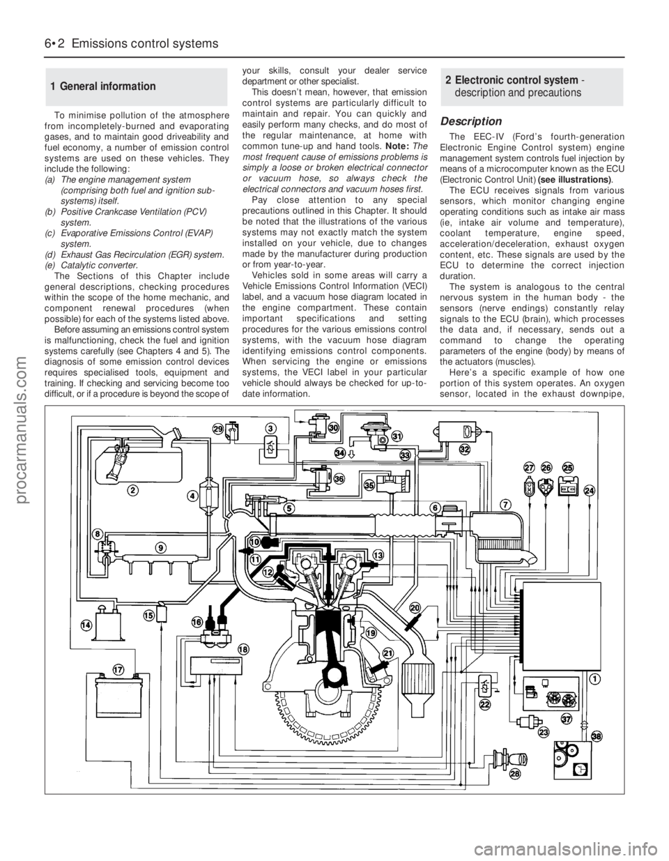
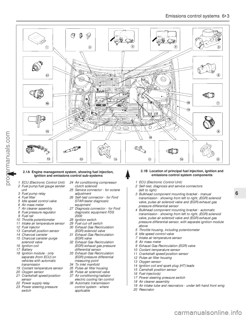
(Electronic Control Unit) (see illustrations).
The ECU receives signals from various
sensors, which monitor changing engine
operating conditions such as intake air mass
(ie, intake air volume and temperature),
coolant temperature, engine speed,
acceleration/deceleration, exhaust oxygen
content, etc. These signals are used by the
ECU to determine the correct injection
duration.
The system is analogous to the central
nervous system in the human body - the
sensors (nerve endings) constantly relay
signals to the ECU (brain), which processes
the data and, if necessary, sends out a
command to change the operating
parameters of the engine (body) by means of
the actuators (muscles).
Here’s a specific example of how one
portion of this system operates. An oxygen
sensor, located in the exhaust downpipe,
2 Electronic control system -
description and precautions1 General information
6•2 Emissions control systems
procarmanuals.com
Page 137 of 279
Emissions control systems 6•3
6
2.1B Location of principal fuel injection, ignition and
emissions control system components 2.1A Engine management system, showing fuel injection,
ignition and emissions control sub-systems
1 ECU (Electronic Control Unit)
2 Fuel pump/fuel gauge sender
unit
3 Fuel pump relay
4 Fuel filter
5 Idle speed control valve
6 Air mass meter
7 Air cleaner assembly
8 Fuel pressure regulator
9 Fuel rail
10 Throttle potentiometer
11 Intake air temperature sensor
12 Fuel injector
13 Camshaft position sensor
14 Charcoal canister
15 Charcoal canister-purge
solenoid valve
16 Ignition coil
17 Battery
18 Ignition module - only
separate (from ECU) on
vehicles with automatic
transmission
19 Coolant temperature sensor
20 Oxygen sensor
21 Crankshaft speed/position
sensor
22 Power supply relay
23 Power steering pressure
switch24 Air conditioning compressor
clutch solenoid
25 Service connector - for octane
adjustment
26 Self-test connector - for Ford
STAR tester diagnostic
equipment
27 Diagnosis connector - for Ford
diagnostic equipment FDS
2000
28 Ignition switch
29 Fuel cut-off switch
30 Exhaust Gas Recirculation
(EGR) solenoid valve
31 Exhaust Gas Recirculation
(EGR) valve
32 Exhaust Gas Recirculation
(EGR) exhaust gas pressure
differential sensor
33 Exhaust Gas Recirculation
(EGR) pressure differential
measuring point
34 To inlet manifold
35 Pulse-air filter housing
36 Pulse-air solenoid valve
37 Air conditioning/radiator
electric cooling fan control
38 Automatic transmission
control system - where
applicable1 ECU (Electronic Control Unit)
2 Self-test, diagnosis and service connectors
(left to right)
3 Bulkhead component mounting bracket - manual
transmission - showing from left to right, (EGR) solenoid
valve, pulse-air solenoid valve and (EGR) exhaust gas
pressure differential sensor
4 Bulkhead component mounting bracket - automatic
transmission - showing from left to right, (EGR) solenoid
valve, pulse-air solenoid valve and (EGR) exhaust gas
pressure differential sensor, with separate ignition module
above
5 Throttle housing, including potentiometer
6 Idle speed control valve
7 Intake air temperature sensor
8 Air mass meter
9 Exhaust Gas Recirculation (EGR) valve
10 Coolant temperature sensor
11 Crankshaft speed/position sensor
12 Pulse-air filter housing
13 Oxygen sensor
14 Ignition coil and spark plug (HT) leads
15 Camshaft position sensor
16 Fuel injector(s)
17 Power steering pressure switch
18 Air cleaner assembly
19 Air intake tube and resonators - under left-hand front wing
20 Resonator
procarmanuals.com
Page 139 of 279
coolant or EGR pipes, etc. In almost all cases,
damage of this sort is caused in the first
instance by incorrect routing on reassembly
after previous work has been carried out (see
the note at the beginning of this sub-Section).
6Obviously wires can break or short together
inside the insulation so that no visible
evidence betrays the fault, but this usually
only occurs where the wiring loom has been
incorrectly routed so that it is stretched taut or
kinked sharply; either of these conditions
should be obvious on even a casual
inspection. If this is thought to have happened
and the fault proves elusive, the suspect
section of wiring should be checked very
carefully during the more detailed checks
which follow.
7Depending on the extent of the problem,
damaged wiring may be repaired by rejoining
the break or splicing-in a new length of wire,
using solder to ensure a good connection,
and remaking the insulation with adhesive
insulating tape or heat-shrink tubing, as
desired. If the damage is extensive, given the
implications for the vehicle’s future reliability,
the best long-term answer may well be to
renew that entire section of the loom, however
expensive this may appear.
8When the actual damage has been
repaired, ensure that the wiring loom is
rerouted correctly, so that it is clear of other
components, is not stretched or kinked, and is
secured out of harm’s way using the plastic
clips, guides and ties provided.
9Check all electrical connectors, ensuring
that they are clean, securely fastened, and
that each is locked by its plastic tabs or wire
clip, as appropriate. If any connector shows
external signs of corrosion (accumulations of
white or green deposits, or streaks of “rust”),
or if any is thought to be dirty, it must be
unplugged and cleaned using electrical
contact cleaner. If the connector pins are
severely corroded, the connector must be
renewed; note that this may mean the renewalof that entire section of the loom - see your
local Ford dealer for details.
10If the cleaner completely removes the
corrosion to leave the connector in a
satisfactory condition, it would be wise to
pack the connector with a suitable material
which will exclude dirt and moisture, and
prevent the corrosion from occurring again; a
Ford dealer may be able to recommend a
suitable product. Note:The system’s
connectors use gold-plated pins, which must
notbe mixed with the older tin-plated types
(readily identifiable from the different colour) if
a component is renewed, nor must the lithium
grease previously used to protect tin-plated
pins be used on gold-plated connectors.
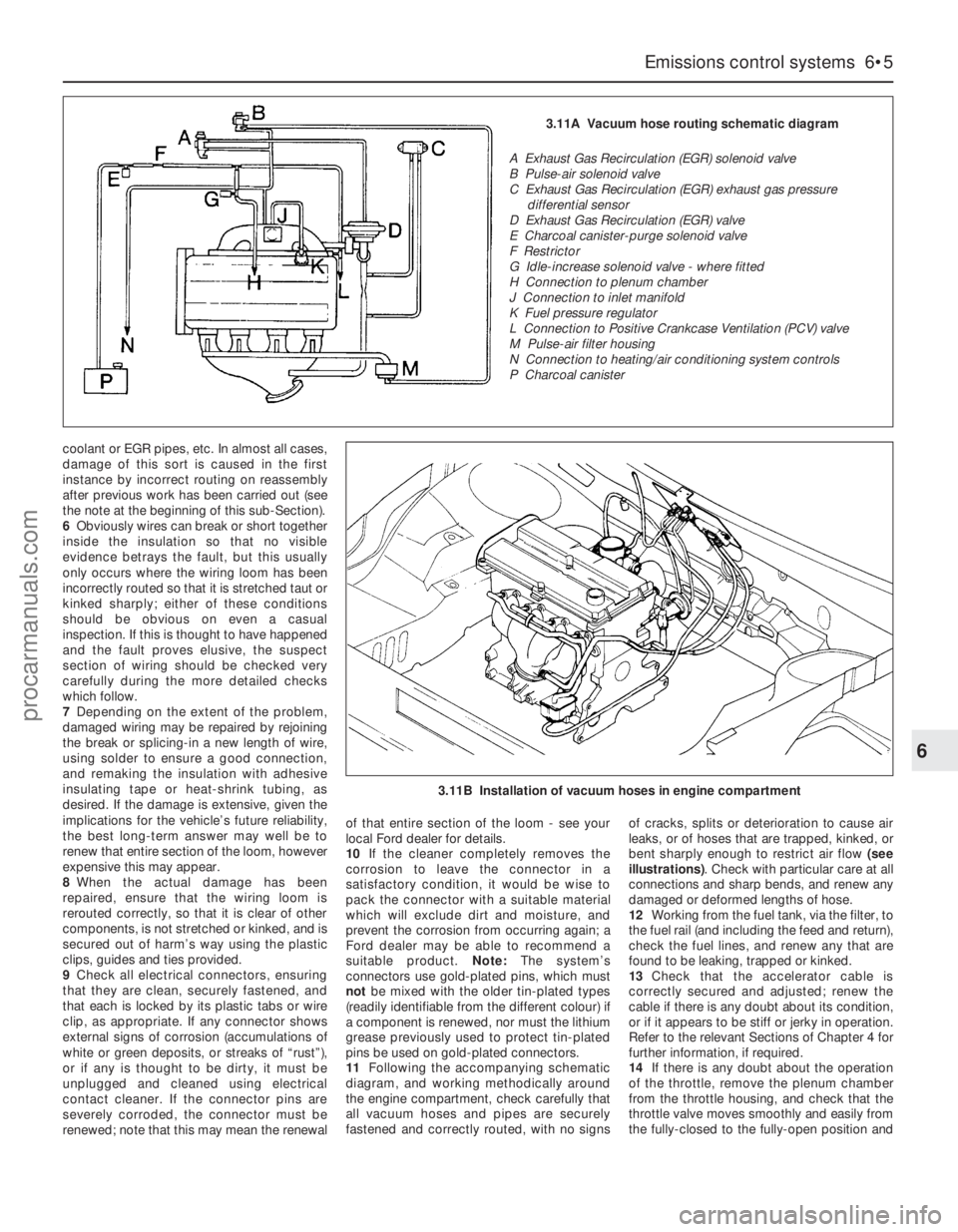
11Following the accompanying schematic
diagram, and working methodically around
the engine compartment, check carefully that
all vacuum hoses and pipes are securely
fastened and correctly routed, with no signsof cracks, splits or deterioration to cause air
leaks, or of hoses that are trapped, kinked, or
bent sharply enough to restrict air flow (see
illustrations). Check with particular care at all
connections and sharp bends, and renew any
damaged or deformed lengths of hose.
12Working from the fuel tank, via the filter, to
the fuel rail (and including the feed and return),
check the fuel lines, and renew any that are
found to be leaking, trapped or kinked.
13Check that the accelerator cable is
correctly secured and adjusted; renew the
cable if there is any doubt about its condition,
or if it appears to be stiff or jerky in operation.
Refer to the relevant Sections of Chapter 4 for
further information, if required.
14If there is any doubt about the operation
of the throttle, remove the plenum chamber
from the throttle housing, and check that the
throttle valve moves smoothly and easily from
the fully-closed to the fully-open position and
Emissions control systems 6•5
6
3.11A Vacuum hose routing schematic diagram
A Exhaust Gas Recirculation (EGR) solenoid valve
B Pulse-air solenoid valve
C Exhaust Gas Recirculation (EGR) exhaust gas pressure
differential sensor
D Exhaust Gas Recirculation (EGR) valve
E Charcoal canister-purge solenoid valve
F Restrictor
G Idle-increase solenoid valve - where fitted
H Connection to plenum chamber
J Connection to inlet manifold
K Fuel pressure regulator
L Connection to Positive Crankcase Ventilation (PCV) valve
M Pulse-air filter housing
N Connection to heating/air conditioning system controls
P Charcoal canister
3.11B Installation of vacuum hoses in engine compartment
procarmanuals.com
Page 141 of 279
24Ford specify the use of their STAR (Self-
Test Automatic Readout) tester; most Ford
dealers should have such equipment, and the
staff trained to use it effectively. The only
alternatives are as follows:
(a) To obtain one of those proprietary readers
which can interpret EEC-IV three-digit
codes - at present, such readers are too
expensive for the DIY enthusiast, but are
becoming more popular with smaller
specialist garages.
(b) To use an analogue voltmeter, whereby
the stored codes are displayed as sweeps
of the voltmeter needle. This option limits
the operator to a read-out of any codes
stored - ie, there is no control of sensors
and/or actuators - but can still be useful in
pinpointing the faulty part of the engine
management system. The display is
interpreted as follows. Each code
(whether fault code or
command/separator) is marked by a
three-to-four second pause - code “538”
would therefore be shown as long (3 to
4 seconds) pause, five fast sweeps of the
needle, slight (1 second) pause, three fast
sweeps, slight pause, eight fast sweeps,
long pause.
(c) Owners without access to such
equipment must take the vehicle to a Ford
dealer, or to an expert who has similar
equipment and the skill to use it.
25Because of the variations in the design of
fault code readers, it is not possible to give
exact details of the sequence of tests; the
manufacturer’s instructions must be followed,
in conjunction with the codes given below.
The following ten paragraphs outline the
procedure to be followed using a version of
the Ford STAR tester, to illustrate the general
principles, as well as notes to guide the owner
using only a voltmeter.
26The vehicle must be prepared by applying
the handbrake, switching off the air
conditioning (where fitted) and any other
electrical loads (lights, heated rear window,
etc), then selecting neutral (manual
transmission) or the “P” position (automatic
transmission). Where the engine is required to
be running, it must be fully warmed-up to
normal operating temperature before the test
is started. Using any adaptors required,
connect the fault code reader to the system
via the (triangular, three-pin) self-test
connector on the right-hand end of the engine
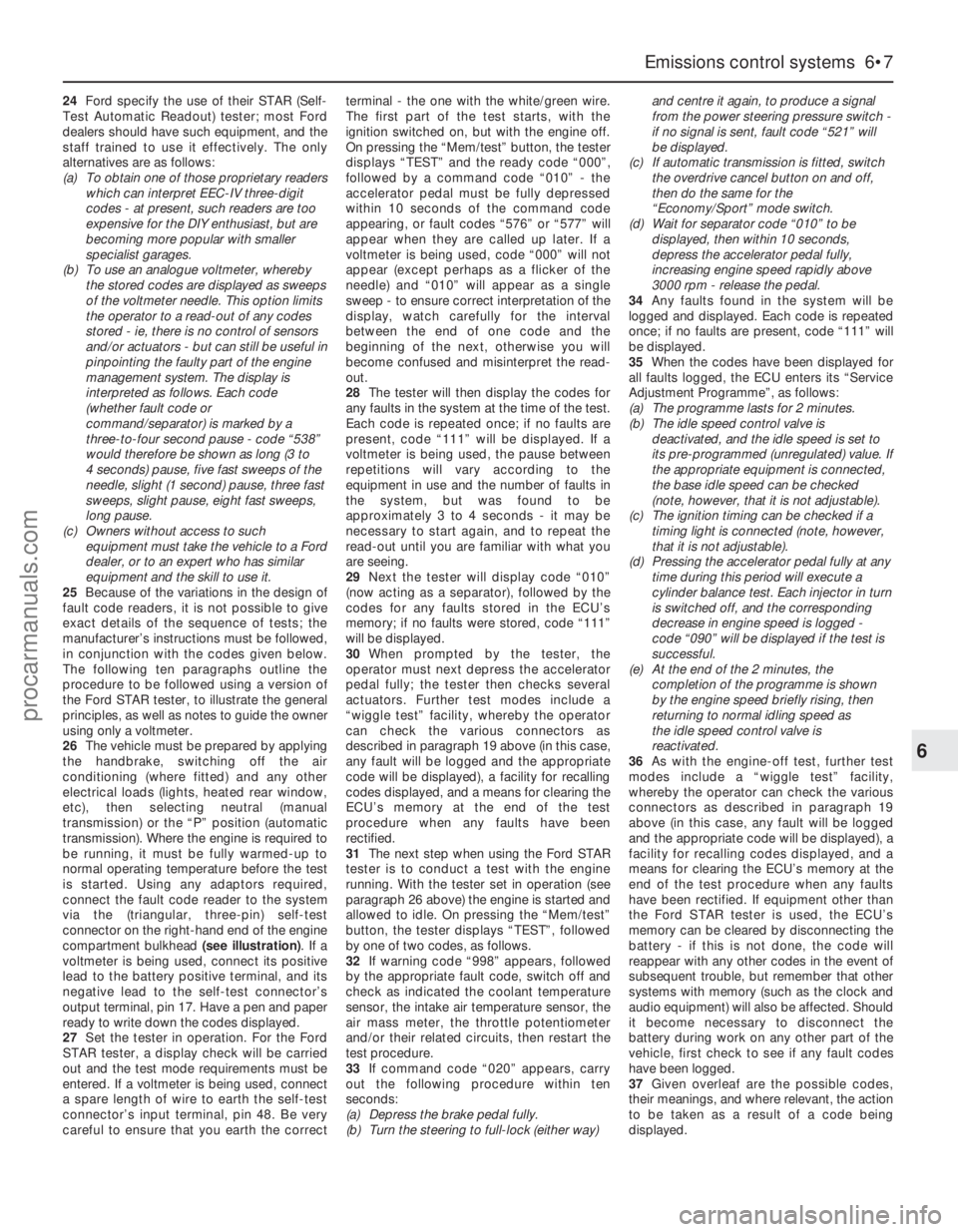
compartment bulkhead (see illustration). If a
voltmeter is being used, connect its positive
lead to the battery positive terminal, and its
negative lead to the self-test connector’s
output terminal, pin 17. Have a pen and paper
ready to write down the codes displayed.
27Set the tester in operation. For the Ford
STAR tester, a display check will be carried
out and the test mode requirements must be
entered. If a voltmeter is being used, connect
a spare length of wire to earth the self-test
connector’s input terminal, pin 48. Be very
careful to ensure that you earth the correctterminal - the one with the white/green wire.
The first part of the test starts, with the
ignition switched on, but with the engine off.
On pressing the “Mem/test” button, the tester
displays “TEST” and the ready code “000”,
followed by a command code “010” - the
accelerator pedal must be fully depressed
within 10 seconds of the command code
appearing, or fault codes “576” or “577” will
appear when they are called up later. If a
voltmeter is being used, code “000” will not
appear (except perhaps as a flicker of the
needle) and “010” will appear as a single
sweep - to ensure correct interpretation of the
display, watch carefully for the interval
between the end of one code and the
beginning of the next, otherwise you will
become confused and misinterpret the read-
out.
28The tester will then display the codes for
any faults in the system at the time of the test.
Each code is repeated once; if no faults are
present, code “111” will be displayed. If a
voltmeter is being used, the pause between
repetitions will vary according to the
equipment in use and the number of faults in
the system, but was found to be
approximately 3 to 4 seconds - it may be
necessary to start again, and to repeat the
read-out until you are familiar with what you
are seeing.
29Next the tester will display code “010”
(now acting as a separator), followed by the
codes for any faults stored in the ECU’s
memory; if no faults were stored, code “111”
will be displayed.
30When prompted by the tester, the
operator must next depress the accelerator
pedal fully; the tester then checks several
actuators. Further test modes include a
“wiggle test” facility, whereby the operator
can check the various connectors as
described in paragraph 19 above (in this case,
any fault will be logged and the appropriate
code will be displayed), a facility for recalling
codes displayed, and a means for clearing the
ECU’s memory at the end of the test
procedure when any faults have been
rectified.
31The next step when using the Ford STAR
tester is to conduct a test with the engine
running. With the tester set in operation (see
paragraph 26 above) the engine is started and
allowed to idle. On pressing the “Mem/test”
button, the tester displays “TEST”, followed
by one of two codes, as follows.
32If warning code “998” appears, followed
by the appropriate fault code, switch off and
check as indicated the coolant temperature
sensor, the intake air temperature sensor, the
air mass meter, the throttle potentiometer
and/or their related circuits, then restart the
test procedure.
33If command code “020” appears, carry
out the following procedure within ten
seconds:
(a) Depress the brake pedal fully.
(b) Turn the steering to full-lock (either way)and centre it again, to produce a signal
from the power steering pressure switch -
if no signal is sent, fault code “521” will
be displayed.
(c) If automatic transmission is fitted, switch
the overdrive cancel button on and off,
then do the same for the
“Economy/Sport” mode switch.
(d) Wait for separator code “010” to be
displayed, then within 10 seconds,
depress the accelerator pedal fully,
increasing engine speed rapidly above
3000 rpm - release the pedal.
34Any faults found in the system will be
logged and displayed. Each code is repeated
once; if no faults are present, code “111” will
be displayed.
35When the codes have been displayed for
all faults logged, the ECU enters its “Service
Adjustment Programme”, as follows:
(a) The programme lasts for 2 minutes.
(b) The idle speed control valve is
deactivated, and the idle speed is set to
its pre-programmed (unregulated) value. If
the appropriate equipment is connected,
the base idle speed can be checked
(note, however, that it is not adjustable).
(c) The ignition timing can be checked if a
timing light is connected (note, however,
that it is not adjustable).
(d) Pressing the accelerator pedal fully at any
time during this period will execute a
cylinder balance test. Each injector in turn
is switched off, and the corresponding
decrease in engine speed is logged -
code “090” will be displayed if the test is
successful.
(e) At the end of the 2 minutes, the
completion of the programme is shown
by the engine speed briefly rising, then
returning to normal idling speed as
the idle speed control valve is
reactivated.
36As with the engine-off test, further test
modes include a “wiggle test” facility,
whereby the operator can check the various
connectors as described in paragraph 19
above (in this case, any fault will be logged
and the appropriate code will be displayed), a
facility for recalling codes displayed, and a
means for clearing the ECU’s memory at the
end of the test procedure when any faults
have been rectified. If equipment other than
the Ford STAR tester is used, the ECU’s
memory can be cleared by disconnecting the
battery - if this is not done, the code will
reappear with any other codes in the event of
subsequent trouble, but remember that other
systems with memory (such as the clock and
audio equipment) will also be affected. Should
it become necessary to disconnect the
battery during work on any other part of the
vehicle, first check to see if any fault codes
have been logged.
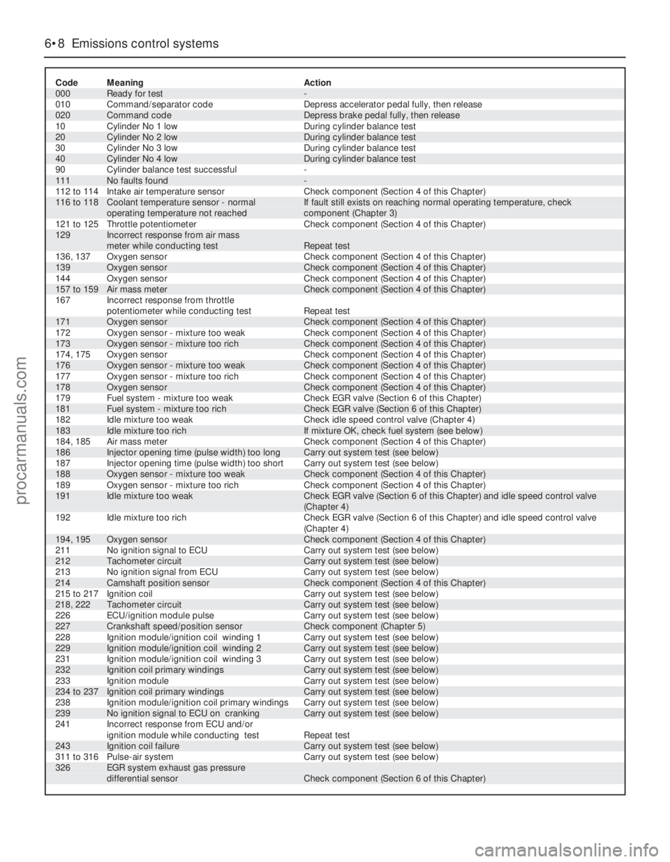
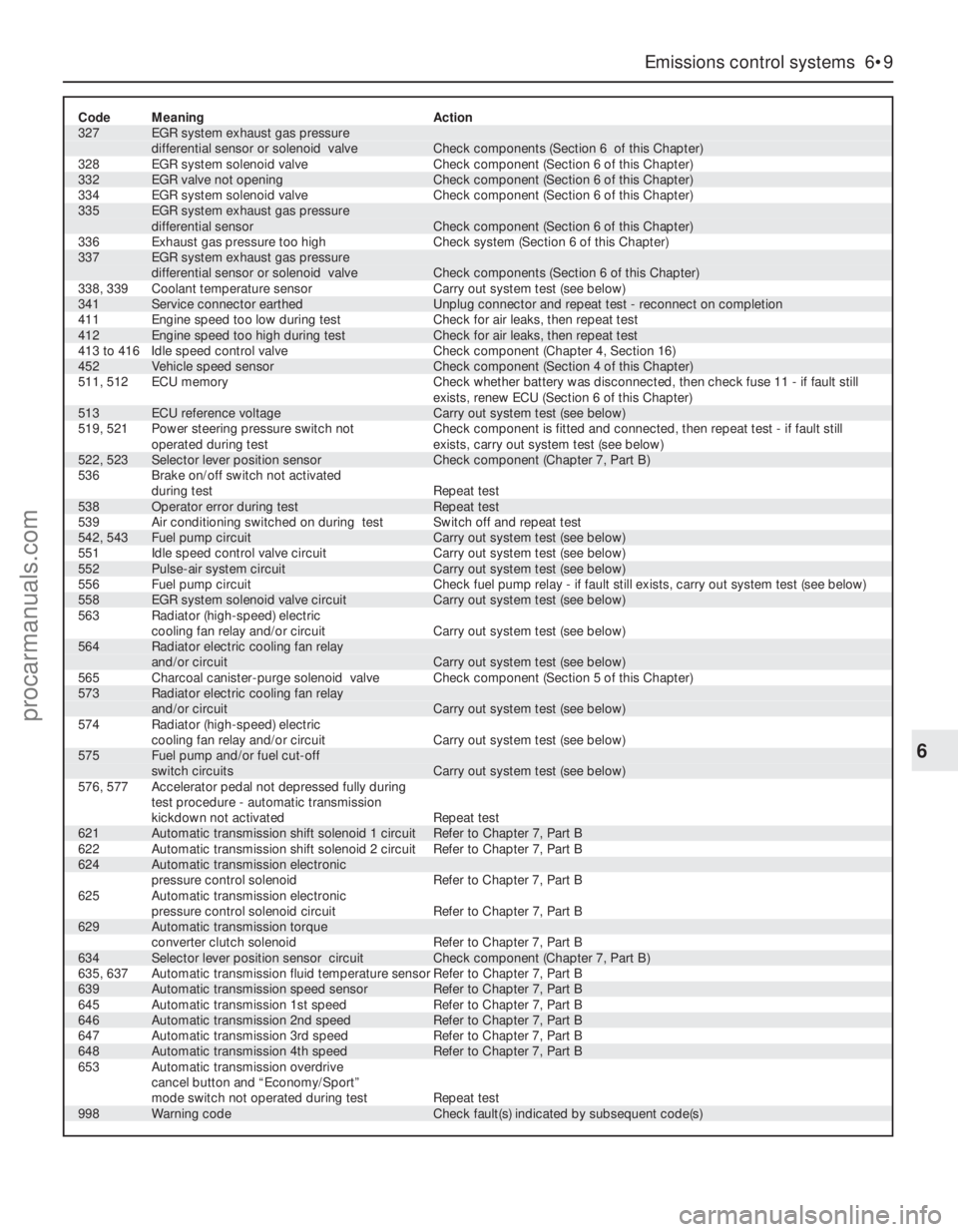
37Given overleaf are the possible codes,
their meanings, and where relevant, the action
to be taken as a result of a code being
displayed.
Emissions control systems 6•7
6
procarmanuals.com
Page 142 of 279
6•8 Emissions control systems
Code Meaning Action
000 Ready for test -
010 Command/separator code Depress accelerator pedal fully, then release
020 Command code Depress brake pedal fully, then release
10 Cylinder No 1 low During cylinder balance test
20 Cylinder No 2 low During cylinder balance test
30 Cylinder No 3 low During cylinder balance test
40 Cylinder No 4 low During cylinder balance test
90 Cylinder balance test successful -
111 No faults found -
112 to 114 Intake air temperature sensor Check component (Section 4 of this Chapter)116 to 118 Coolant temperature sensor - normal If fault still exists on reaching normal operating temperature, check
operating temperature not reached component (Chapter 3)
121 to 125 Throttle potentiometer Check component (Section 4 of this Chapter)129 Incorrect response from air mass
meter while conducting test Repeat test
136, 137 Oxygen sensor Check component (Section 4 of this Chapter)
139 Oxygen sensor Check component (Section 4 of this Chapter)
144 Oxygen sensor Check component (Section 4 of this Chapter)
157 to 159 Air mass meter Check component (Section 4 of this Chapter)
167 Incorrect response from throttle
potentiometer while conducting test Repeat test
171 Oxygen sensor Check component (Section 4 of this Chapter)
172 Oxygen sensor - mixture too weak Check component (Section 4 of this Chapter)
173 Oxygen sensor - mixture too rich Check component (Section 4 of this Chapter)
174, 175 Oxygen sensor Check component (Section 4 of this Chapter)
176 Oxygen sensor - mixture too weak Check component (Section 4 of this Chapter)
177 Oxygen sensor - mixture too rich Check component (Section 4 of this Chapter)
178 Oxygen sensor Check component (Section 4 of this Chapter)
179 Fuel system - mixture too weak Check EGR valve (Section 6 of this Chapter)
181 Fuel system - mixture too rich Check EGR valve (Section 6 of this Chapter)
182 Idle mixture too weak Check idle speed control valve (Chapter 4)
183 Idle mixture too rich If mixture OK, check fuel system (see below)
184, 185 Air mass meter Check component (Section 4 of this Chapter)
186 Injector opening time (pulse width) too long Carry out system test (see below)
187 Injector opening time (pulse width) too short Carry out system test (see below)
188 Oxygen sensor - mixture too weak Check component (Section 4 of this Chapter)
189 Oxygen sensor - mixture too rich Check component (Section 4 of this Chapter)191 Idle mixture too weak Check EGR valve (Section 6 of this Chapter) and idle speed control valve
(Chapter 4)
192 Idle mixture too rich Check EGR valve (Section 6 of this Chapter) and idle speed control valve
(Chapter 4)
194, 195 Oxygen sensor Check component (Section 4 of this Chapter)
211 No ignition signal to ECU Carry out system test (see below)
212 Tachometer circuit Carry out system test (see below)
213 No ignition signal from ECU Carry out system test (see below)
214 Camshaft position sensor Check component (Section 4 of this Chapter)
215 to 217 Ignition coil Carry out system test (see below)
218, 222 Tachometer circuit Carry out system test (see below)
226 ECU/ignition module pulse Carry out system test (see below)
227 Crankshaft speed/position sensor Check component (Chapter 5)
228 Ignition module/ignition coil winding 1 Carry out system test (see below)
229 Ignition module/ignition coil winding 2 Carry out system test (see below)
231 Ignition module/ignition coil winding 3 Carry out system test (see below)
232 Ignition coil primary windings Carry out system test (see below)
233 Ignition module Carry out system test (see below)
234 to 237 Ignition coil primary windings Carry out system test (see below)
238 Ignition module/ignition coil primary windings Carry out system test (see below)
239 No ignition signal to ECU on cranking Carry out system test (see below)
241 Incorrect response from ECU and/or
ignition module while conducting test Repeat test
243 Ignition coil failure Carry out system test (see below)
311 to 316 Pulse-air system Carry out system test (see below)326 EGR system exhaust gas pressure
differential sensor Check component (Section 6 of this Chapter)
procarmanuals.com
Page 143 of 279
Code Meaning Action327 EGR system exhaust gas pressure
differential sensor or solenoid valve Check components (Section 6 of this Chapter)
328 EGR system solenoid valve Check component (Section 6 of this Chapter)
332 EGR valve not opening Check component (Section 6 of this Chapter)
334 EGR system solenoid valve Check component (Section 6 of this Chapter)335 EGR system exhaust gas pressure
differential sensor Check component (Section 6 of this Chapter)
336 Exhaust gas pressure too high Check system (Section 6 of this Chapter)337 EGR system exhaust gas pressure
differential sensor or solenoid valve Check components (Section 6 of this Chapter)
338, 339 Coolant temperature sensor Carry out system test (see below)
341 Service connector earthed Unplug connector and repeat test - reconnect on completion
411 Engine speed too low during test Check for air leaks, then repeat test
412 Engine speed too high during test Check for air leaks, then repeat test
413 to 416 Idle speed control valve Check component (Chapter 4, Section 16)
452 Vehicle speed sensor Check component (Section 4 of this Chapter)
511, 512 ECU memory Check whether battery was disconnected, then check fuse 11 - if fault still
exists, renew ECU (Section 6 of this Chapter)
513 ECU reference voltage Carry out system test (see below)
519, 521 Power steering pressure switch not Check component is fitted and connected, then repeat test - if fault still
operated during test exists, carry out system test (see below)
522, 523 Selector lever position sensor Check component (Chapter 7, Part B)
536 Brake on/off switch not activated
during test Repeat test
538 Operator error during test Repeat test
539 Air conditioning switched on during test Switch off and repeat test
542, 543 Fuel pump circuit Carry out system test (see below)
551 Idle speed control valve circuit Carry out system test (see below)
552 Pulse-air system circuit Carry out system test (see below)
556 Fuel pump circuit Check fuel pump relay - if fault still exists, carry out system test (see below)
558 EGR system solenoid valve circuit Carry out system test (see below)
563 Radiator (high-speed) electric
cooling fan relay and/or circuit Carry out system test (see below)564 Radiator electric cooling fan relay
and/or circuit Carry out system test (see below)
565 Charcoal canister-purge solenoid valve Check component (Section 5 of this Chapter)573 Radiator electric cooling fan relay
and/or circuit Carry out system test (see below)
574 Radiator (high-speed) electric
cooling fan relay and/or circuit Carry out system test (see below)575 Fuel pump and/or fuel cut-off
switch circuits Carry out system test (see below)
576, 577 Accelerator pedal not depressed fully during
test procedure - automatic transmission
kickdown not activated Repeat test
621 Automatic transmission shift solenoid 1 circuit Refer to Chapter 7, Part B
622 Automatic transmission shift solenoid 2 circuit Refer to Chapter 7, Part B
624 Automatic transmission electronic
pressure control solenoid Refer to Chapter 7, Part B
625 Automatic transmission electronic
pressure control solenoid circuit Refer to Chapter 7, Part B
629 Automatic transmission torque
converter clutch solenoid Refer to Chapter 7, Part B
634 Selector lever position sensor circuit Check component (Chapter 7, Part B)
635, 637 Automatic transmission fluid temperature sensor Refer to Chapter 7, Part B
639 Automatic transmission speed sensor Refer to Chapter 7, Part B
645 Automatic transmission 1st speed Refer to Chapter 7, Part B
646 Automatic transmission 2nd speed Refer to Chapter 7, Part B
647 Automatic transmission 3rd speed Refer to Chapter 7, Part B
648 Automatic transmission 4th speed Refer to Chapter 7, Part B
653 Automatic transmission overdrive
cancel button and “Economy/Sport”
mode switch not operated during test Repeat test
998 Warning code Check fault(s) indicated by subsequent code(s)
Emissions control systems 6•9
6
procarmanuals.com