1993 FORD MONDEO coolant
[x] Cancel search: coolantPage 145 of 279
passes the sensor tip, a signal is generated,
which is used by the ECU to determine engine
speed.
4The ridge between the 35th and 36th holes
(corresponding to 90° BTDC) is missing - this
step in the incoming signals is used by the
ECU to determine crankshaft (ie, piston)
position.
Camshaft position sensor
5This is bolted to the rear left-hand end of
the cylinder head, to register with a lobe on
the inlet camshaft. It functions in the same
way as the crankshaft speed/position sensor,
producing a series of pulses (corresponding
to No 1 cylinder at 46° ATDC); this gives the
ECU a reference point, to enable it to
determine the firing order, and operate the
injectors in the appropriate sequence.
Coolant temperature sensor
6This component, which is screwed into the
top of the thermostat housing, is an NTC
(Negative Temperature Coefficient) thermistor
- that is, a semi-conductor whose electrical
resistance decreases as its temperature
increases. It provides the ECU with a
constantly-varying (analogue) voltage signal,
corresponding to the temperature of the
engine coolant. This is used to refine the
calculations made by the ECU, when
determining the correct amount of fuel
required to achieve the ideal air/fuel mixture
ratio.
Intake air temperature sensor
7This component, which is screwed into the
underside of the air intake resonator, is also an
NTC thermistor - see the previous paragraph -
providing the ECU with a signal corresponding
to the temperature of air passing into the
engine. This is used to refine the calculations
made by the ECU, when determining the
correct amount of fuel required to achieve the
ideal air/fuel mixture ratio.
Throttle potentiometer
8This is mounted on the end of the throttle
valve spindle, to provide the ECU with a
constantly-varying (analogue) voltage signal
corresponding to the throttle opening. This
allows the ECU to register the driver’s input
when determining the amount of fuel required
by the engine.
Vehicle speed sensor
9This component is a Hall-effect generator,
mounted on the transmission’s speedometer
drive. It supplies the ECU with a series of
pulses corresponding to the vehicle’s road
speed, enabling the ECU to control features
such as the fuel shut-off on the overrun, and
to provide information for the trip computer,
adaptive damping and cruise control systems
(where fitted).
Power steering pressure switch
10This is a pressure-operated switch,
screwed into the power steering system’shigh-pressure pipe. Its contacts are normally
closed, opening when the system reaches the
specified pressure - on receiving this signal,
the ECU increases the idle speed, to
compensate for the additional load on the
engine.
Exhaust gas pressure differential
sensor
11This component measures the difference
in pressure of the exhaust gases across a
venturi (restriction) in the Exhaust Gas
Recirculation (EGR) system’s pipe, and sends
the ECU a voltage signal corresponding to the
pressure difference.
Oxygen sensor
12The oxygen sensor in the exhaust system
provides the ECU with constant feedback -
“closed-loop” control - which enables it to
adjust the mixture to provide the best possible
conditions for the catalytic converter to
operate.
13The sensor has a built-in heating element
which is controlled by the ECU, in order to
bring the sensor’s tip to an efficient operating
temperature as rapidly as possible. The
sensor’s tip is sensitive to oxygen, and sends
the ECU a varying voltage depending on the
amount of oxygen in the exhaust gases. If the
intake air/fuel mixture is too rich, the exhaust
gases are low in oxygen, so the sensor sends
a low-voltage signal, the voltage rising as the
mixture weakens and the amount of oxygen in
the exhaust gases rises. Peak conversion
efficiency of all major pollutants occurs if the
intake air/fuel mixture is maintained at the
chemically-correct ratio for the complete
combustion of petrol, of 14.7 parts (by weight)
of air to 1 part of fuel (the “stoichiometric”
ratio). The sensor output voltage alters sharply
around this point, the ECU using the signal
change as a reference point, and correcting
the air/fuel mixture by altering the fuel injector
pulse width.
Air conditioning system
14Two pressure-operated switches and the
compressor clutch solenoid are connected to
the ECU, to enable it to determine how the
system is operating. The ECU can increase
idle speed or switch off the system, as
necessary, so that normal vehicle operation
and driveability are not impaired. See Chapter
3 for further details, but note that diagnosis
and repair should be left to a dealer service
department or air conditioning specialist.
Automatic transmission
15In addition to the driver’s controls, the
transmission has a speed sensor, a fluid
temperature sensor (built into the solenoid
valve unit), and a selector lever position
sensor. All of these are connected to the ECU,
to enable it to control the transmission
through the solenoid valve unit. See Part B of
Chapter 7 for further details.
Testing
ECU (Electronic Control Unit)
16 Do notattempt to “test” the ECU with any
kind of equipment. If it is thought to be faulty,
take the vehicle to a Ford dealer for the entire
electronic control system to be checked using
the proper diagnostic equipment. Only if all
other possibilities have been eliminated should
the ECU be considered at fault, and replaced.
Air mass meter
17Testing of this component is beyond the
scope of the DIY mechanic, and should be left
to a Ford dealer.
Crankshaft speed/position sensor
18Unplug the electrical connector from the
sensor.
19Using an ohmmeter, measure the
resistance between the sensor terminals.
Compare this reading to the one listed in the
Specifications Section at the beginning of this
Chapter. If the indicated resistance is not
within the specified range, renew the sensor.
20Plug in the sensor’s electrical connector
on completion.
Camshaft position sensor
21The procedure is as described in
paragraphs 18 to 20 above.
Coolant temperature sensor
22Refer to Chapter 3.
Intake air temperature sensor
23Unplug the electrical connector from the
sensor.
24Using an ohmmeter, measure the
resistance between the sensor terminals.
Depending on the temperature of the sensor
tip, the resistance measured will vary, but it
should be within the broad limits given in the
Specifications Section of this Chapter. If the
sensor’s temperature is varied - by placing it
in a freezer for a while, or by warming it gently
- its resistance should alter accordingly.
25If the results obtained show the sensor to
be faulty, renew it.
Throttle potentiometer
26Remove the plenum chamber (see
Chapter 4) and unplug the potentiometer’s
electrical connector.
27Using an ohmmeter, measure the
resistance between the unit’s terminals - first
between the centre terminal and one of the
outer two, then from the centre to the
remaining outer terminal. The resistance
should be within the limits given in the
Specifications Section of this Chapter, and
should alter smoothlyas the throttle valve is
moved from the fully-closed (idle speed)
position to fully open and back again.
28If the resistance measured is significantly
different from the specified value, if there are
any breaks in continuity, or if the reading
fluctuates erratically as the throttle is
operated, the potentiometer is faulty, and
must be renewed.
Emissions control systems 6•11
6
procarmanuals.com
Page 147 of 279
(a) Apply petroleum jelly or clean engine oil
to the sensor’s sealing O-ring.
(b) Locate the sensor fully in the cylinder
head, and wipe off any surplus lubricant
before securing it.
(c) Tighten the screw to the specified torque
wrench setting.
Coolant temperature sensor
48Refer to Chapter 3, Section 6.
Intake air temperature sensor
49Remove the air mass meter and resonator
(refer to Chapter 4) to gain access to the
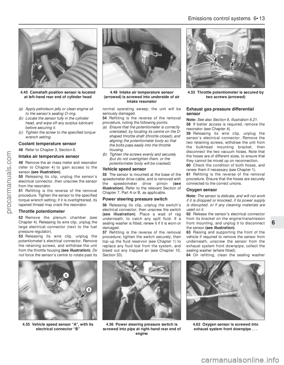
sensor (see illustration).
50Releasing its clip, unplug the sensor’s
electrical connector, then unscrew the sensor
from the resonator.
51Refitting is the reverse of the removal
procedure. Tighten the sensor to the specified
torque wrench setting; if it is overtightened, its
tapered thread may crack the resonator.
Throttle potentiometer
52Remove the plenum chamber (see
Chapter 4). Releasing its wire clip, unplug the
large electrical connector (next to the fuel
pressure regulator).
53Releasing its wire clip, unplug the
potentiometer’s electrical connector. Remove
the retaining screws, and withdraw the unit
from the throttle housing (see illustration). Do
notforce the sensor’s centre to rotate past itsnormal operating sweep; the unit will be
seriously damaged.
54Refitting is the reverse of the removal
procedure, noting the following points:
(a) Ensure that the potentiometer is correctly
orientated, by locating its centre on the D-
shaped throttle shaft (throttle closed), and
aligning the potentiometer body so that
the bolts pass easily into the throttle
housing.
(b) Tighten the screws evenly and securely
(but do not overtighten them, or the
potentiometer body will be cracked).
Vehicle speed sensor
55The sensor is mounted at the base of the
speedometer drive cable, and is removed with
the speedometer drive pinion (see
illustration). Refer to the relevant Section of
Chapter 7, Part A or B, as applicable.
Power steering pressure switch
56Releasing its clip, unplug the switch’s
electrical connector, then unscrew the switch
(see illustration). Place a wad of rag
underneath, to catch any spilt fluid. If a
sealing washer is fitted, renew it if it is worn or
damaged.
57Refitting is the reverse of the removal
procedure; tighten the switch securely, then
top-up the fluid reservoir (see Chapter 1) to
replace any fluid lost from the system, and
bleed out any trapped air (see Chapter 10,
Section 33).
Exhaust gas pressure differential
sensor
Note:See also Section 6, illustration 6.21.
58If better access is required, remove the
resonator (see Chapter 4).
59Releasing its wire clip, unplug the
sensor’s electrical connector. Remove the
two retaining screws, withdraw the unit from
the bulkhead mounting bracket, then
disconnect the two vacuum hoses. Note that
the hoses are of different sizes, to ensure that
they cannot be mixed up on reconnection.
60Check the condition of both hoses, and
renew them if necessary (see Chapter 1).
61Refitting is the reverse of the removal
procedure. Ensure that the hoses are securely
connected to the correct unions.
Oxygen sensor
Note:The sensor is delicate, and will not work
if it is dropped or knocked, if its power supply
is disrupted, or if any cleaning materials are
used on it.
62Release the sensor’s electrical connector
from its bracket on the engine/transmission
front mounting, and unplug it to disconnect
the sensor (see illustration).
63Raising and supporting the front of the
vehicle if required to remove the sensor from
underneath, unscrew the sensor from the
exhaust system front downpipe; collect the
sealing washer (where fitted).
64On refitting, clean the sealing washer
Emissions control systems 6•13
6
4.56 Power steering pressure switch is
screwed into pipe at right-hand rear end of
engine4.62 Oxygen sensor is screwed into
exhaust system front downpipe . . .
4.49 Intake air temperature sensor
(arrowed) is screwed into underside of air
intake resonator4.53 Throttle potentiometer is secured by
two screws (arrowed)
4.55 Vehicle speed sensor “A”, with its
electrical connector “B”
4.45 Camshaft position sensor is located
at left-hand rear end of cylinder head
procarmanuals.com
Page 152 of 279
components are worn or damaged, the
assembly must be renewed.
18Refitting is the reverse of the removal
procedure.
Pulse-air piping
Note:This component, and those around it,
will be very hot when the engine is running.
Always allow the engine to cool down fully
before starting work, to prevent the possibility
of burns.
19Disconnect the battery negative (earth)
lead - see Section 1 of Chapter 5.
20Remove the air mass meter and resonator
- refer to Chapter 4.
21Unbolt the exhaust manifold heat shield;
unclip the coolant hose to allow the upper
part to be withdrawn. Apply penetrating oil to
the EGR pipe sleeve nut, and to the pulse-air
system sleeve nuts.
22Remove the EGR pipe (see Section 6).
23Remove the screws securing the filter
housing to the piping - see illustration 7.16.
Unscrew the four sleeve nuts securing the
pipes into the exhaust manifold, and remove
the piping as an assembly, taking care not to
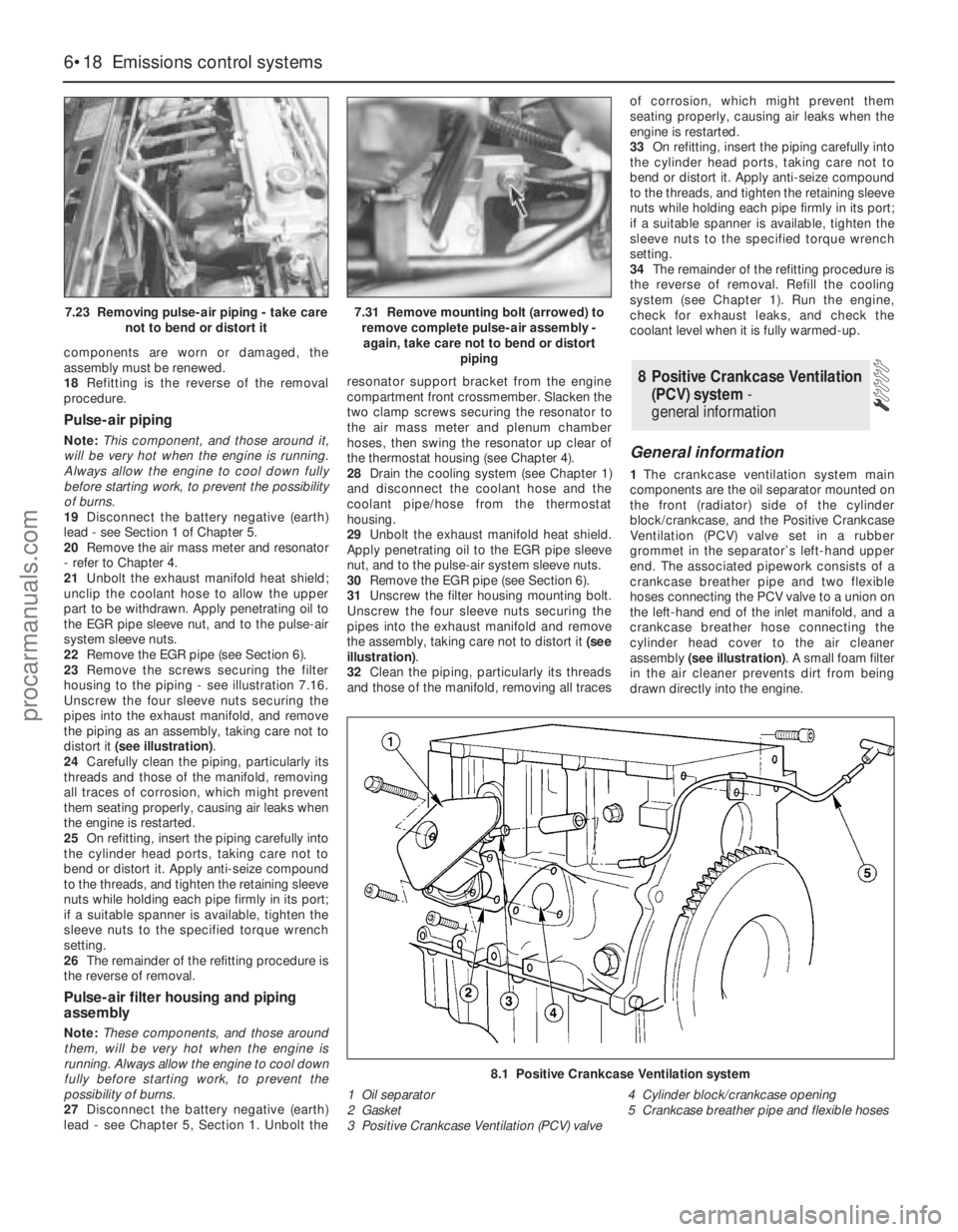
distort it (see illustration).
24Carefully clean the piping, particularly its
threads and those of the manifold, removing
all traces of corrosion, which might prevent
them seating properly, causing air leaks when
the engine is restarted.
25On refitting, insert the piping carefully into
the cylinder head ports, taking care not to
bend or distort it. Apply anti-seize compound
to the threads, and tighten the retaining sleeve
nuts while holding each pipe firmly in its port;
if a suitable spanner is available, tighten the
sleeve nuts to the specified torque wrench
setting.
26The remainder of the refitting procedure is
the reverse of removal.
Pulse-air filter housing and piping
assembly
Note:These components, and those around
them, will be very hot when the engine is
running. Always allow the engine to cool down
fully before starting work, to prevent the
possibility of burns.
27Disconnect the battery negative (earth)
lead - see Chapter 5, Section 1. Unbolt theresonator support bracket from the engine
compartment front crossmember. Slacken the
two clamp screws securing the resonator to
the air mass meter and plenum chamber
hoses, then swing the resonator up clear of
the thermostat housing (see Chapter 4).
28Drain the cooling system (see Chapter 1)
and disconnect the coolant hose and the
coolant pipe/hose from the thermostat
housing.
29Unbolt the exhaust manifold heat shield.
Apply penetrating oil to the EGR pipe sleeve
nut, and to the pulse-air system sleeve nuts.
30Remove the EGR pipe (see Section 6).
31Unscrew the filter housing mounting bolt.
Unscrew the four sleeve nuts securing the
pipes into the exhaust manifold and remove
the assembly, taking care not to distort it (see
illustration).
32Clean the piping, particularly its threads
and those of the manifold, removing all tracesof corrosion, which might prevent them
seating properly, causing air leaks when the
engine is restarted.
33On refitting, insert the piping carefully into
the cylinder head ports, taking care not to
bend or distort it. Apply anti-seize compound
to the threads, and tighten the retaining sleeve
nuts while holding each pipe firmly in its port;
if a suitable spanner is available, tighten the
sleeve nuts to the specified torque wrench
setting.
34The remainder of the refitting procedure is
the reverse of removal. Refill the cooling
system (see Chapter 1). Run the engine,
check for exhaust leaks, and check the
coolant level when it is fully warmed-up.
General information
1The crankcase ventilation system main
components are the oil separator mounted on
the front (radiator) side of the cylinder
block/crankcase, and the Positive Crankcase
Ventilation (PCV) valve set in a rubber
grommet in the separator’s left-hand upper
end. The associated pipework consists of a
crankcase breather pipe and two flexible
hoses connecting the PCV valve to a union on
the left-hand end of the inlet manifold, and a
crankcase breather hose connecting the
cylinder head cover to the air cleaner
assembly (see illustration). A small foam filter
in the air cleaner prevents dirt from being
drawn directly into the engine.
8 Positive Crankcase Ventilation
(PCV) system -
general information
6•18 Emissions control systems
7.23 Removing pulse-air piping - take care
not to bend or distort it7.31 Remove mounting bolt (arrowed) to
remove complete pulse-air assembly -
again, take care not to bend or distort
piping
8.1 Positive Crankcase Ventilation system
1 Oil separator
2 Gasket
3 Positive Crankcase Ventilation (PCV) valve4 Cylinder block/crankcase opening
5 Crankcase breather pipe and flexible hoses
procarmanuals.com
Page 153 of 279
2The function of these components is to
reduce the emission of unburned
hydrocarbons from the crankcase, and to
minimise the formation of oil sludge. By
ensuring that a depression is created in the
crankcase under most operating conditions,
particularly at idle, and by positively inducing
fresh air into the system, the oil vapours and
“blow-by” gases collected in the crankcase
are drawn from the crankcase, through the oil
separator, into the inlet tract, to be burned by
the engine during normal combustion.
Checking
3Checking procedures for the system
components are included in Chapter 1.
Component renewal
Cylinder head-to-air cleaner hose
4See Chapter 1.
Positive Crankcase Ventilation (PCV)
valve
5The valve is plugged into the oil separator.
Depending on the tools available, access to
the valve may be possible once the pulse-air
assembly has been removed (see Section 7).
If this is not feasible, proceed as outlined in
paragraph 6 below.
Oil separator
6Remove the exhaust manifold (see Chap-
ter 2, Part A). The Positive Crankcase
Ventilation (PCV) valve can now be unplugged
and flushed, or renewed, as required, as
described in Chapter 1.
7Unbolt the oil separator from the cylinder
block/crankcase, and withdraw it; remove and
discard the gasket.
8Flush out or renew the oil separator, as
required (see Chapter 1).
9On reassembly, fit a new gasket, and
tighten the fasteners to the torque wrench
settings given in the Specifications Section of
Chapter 2, Part B.
10The remainder of the refitting procedure is
the reverse of removal. Refill the cooling
system (see Chapter 1). Run the engine,
check for exhaust leaks, and check the
coolant level when it is fully warmed-up.
General information
1The exhaust gases of any petrol engine
(however efficient or well-tuned) consist
largely (approximately 99 %) of nitrogen (N
2),
carbon dioxide (CO
2), oxygen (O2), other inert
gases and water vapour (H
2O). The remaining
1 % is made up of the noxious materials
which are currently seen (CO
2apart) as the
major polluters of the environment: carbon
monoxide (CO), unburned hydrocarbons (HC),oxides of nitrogen (NO
x) and some solid
matter, including a small lead content.
2Left to themselves, most of these pollutants
are thought eventually to break down naturally
(CO and NO
x, for example, break down in the
upper atmosphere to release CO
2) having first
caused ground-level environmental problems.
The massive increase world-wide in the use of
motor vehicles, and the current popular
concern for the environment has caused the
introduction in most countries of legislation, in
varying degrees of severity, to combat the
problem.
3The device most commonly used to clean
up vehicle exhausts is the catalytic converter.
It is fitted into the vehicle’s exhaust system,
and uses precious metals (platinum and
palladium or rhodium) as catalysts to speed
up the reaction between the pollutants and
the oxygen in the vehicle’s exhaust gases, CO
and HC being oxidised to form H
2O and CO2and (in the three-way type of catalytic
converter) NO
xbeing reduced to N2. Note:
The catalytic converter is not a filter in the
physical sense; its function is to promote a
chemical reaction, but it is not itself affected
by that reaction.
4The converter consists of an element (or
“substrate”) of ceramic honeycomb, coated
with a combination of precious metals in such
a way as to produce a vast surface area over
which the exhaust gases must flow; the whole
being mounted in a stainless-steel box. A
simple “oxidation” (or “two-way”) catalytic
converter can deal with CO and HC only,
while a “reduction” (or “three-way”) catalytic
converter can deal with CO, HC and NO
x.
Three-way catalytic converters are further
sub-divided into “open-loop” (or
“uncontrolled”) converters which can remove
50 to 70 % of pollutants and “closed-loop”
(also known as “controlled” or “regulated”)
converters which can remove over 90 % of
pollutants.
5The catalytic converter fitted to the Mondeo
models covered in this manual is of the three-
way closed-loop type.
6The catalytic converter is a reliable and
simple device, which needs no maintenance
in itself, but there are some facts of which an
owner should be aware if the converter is to
function properly for its full service life.
(a) DO NOT use leaded petrol in a vehicle
equipped with a catalytic converter - the
lead will coat the precious metals,
reducing their converting efficiency, and
will eventually destroy the converter; it will
also affect the operation of the oxygen
sensor, requiring its renewal if lead-
fouled. Opinions vary as to how much
leaded fuel is necessary to affect the
converter’s performance, and whether it
can recover even if only unleaded petrol is
used afterwards; the best course of action
is, therefore, to assume the worst, and to
ensure that NO leaded petrol is used at
any time.
(b) Always keep the ignition and fuel systemswell-maintained in accordance with the
manufacturer’s schedule (Chapter 1) -
particularly, ensure that the air filter
element, the fuel filter and the spark plugs
are renewed at the correct intervals. If the
intake air/fuel mixture is allowed to
become too rich due to neglect, the
unburned surplus will enter and burn in
the catalytic converter, overheating the
element and eventually destroying the
converter.
(c) If the engine develops a misfire, do not
drive the vehicle at all (or at least as little
as possible) until the fault is cured - the
misfire will allow unburned fuel to enter
the converter, which will result in its
overheating, as noted above. For the
same reason, do not persist if the engine
refuses to start - either trace the problem
and cure it yourself, or have the vehicle
checked immediately by a qualified
mechanic.
(d) Avoid allowing the vehicle to run out of
petrol.
(e) DO NOT push- or tow-start the vehicle
unless no other alternative exists,
especially if the engine and exhaust are at
normal operating temperature. Starting
the engine in this way may soak the
catalytic converter in unburned fuel,
causing it to overheat when the engine
does start - see (b) above.
(f) DO NOT switch off the ignition at high
engine speeds, in particular, do not “blip”
the throttle immediately before switching
off. If the ignition is switched off at
anything above idle speed, unburned fuel
will enter the (very hot) catalytic converter,
with the possible risk of its igniting on the
element and damaging the converter.
(g) Avoid repeated successive cold starts
followed by short journeys. If the
converter is never allowed to reach its
proper working temperature, it will gather
unburned fuel, allowing some to pass into
the atmosphere and the rest to soak in
the element, causing it to overheat when
a long journey is made - see (b) above.
(h) DO NOT use fuel or engine oil additives -
these may contain substances harmful to
the catalytic converter. Similarly, DO NOT
use silicone-based sealants on any part of
the engine or fuel system, and do not use
exhaust sealants on any part of the
exhaust system upstream of the catalytic
converter. Even if the sealant itself does
not contain additives harmful to the
converter, pieces of it may break off and
foul the element, causing local
overheating.
(i) DO NOT continue to use the vehicle if the
engine burns oil to the extent of leaving a
visible trail of blue smoke. Unburned
carbon deposits will clog the converter
passages and reduce its efficiency; in
severe cases, the element will overheat.
(j) Remember that the catalytic converter
operates at very high temperatures -
9 Catalytic converter -
general information, checking
and component renewal
Emissions control systems 6•19
6
procarmanuals.com
Page 219 of 279
the specified mileage (or time) since the last
service has been reached.
4To reset the service interval system and
turn off the light, a switch inside the glovebox
must be depressed for a minimum of 4
seconds with the ignition switched on. This
should be carried out by a Ford dealer if the
vehicle is still in the warranty period.
Component renewal
5The following paragraphs describe brief
removal procedures for the auxiliary warning
system components. Disconnect the battery
negative (earth) lead before commencing
work (refer to Chapter 5, Section 1). Refitting
procedures are a reversal of removal.
Display warning bulb
6Remove the control assembly.
7Prise off the cover, and pull out the relevant
bulb and bulbholder.
Low air temperature warning sender
unit
8Remove the front bumper.
9Unclip the sender unit and disconnect the
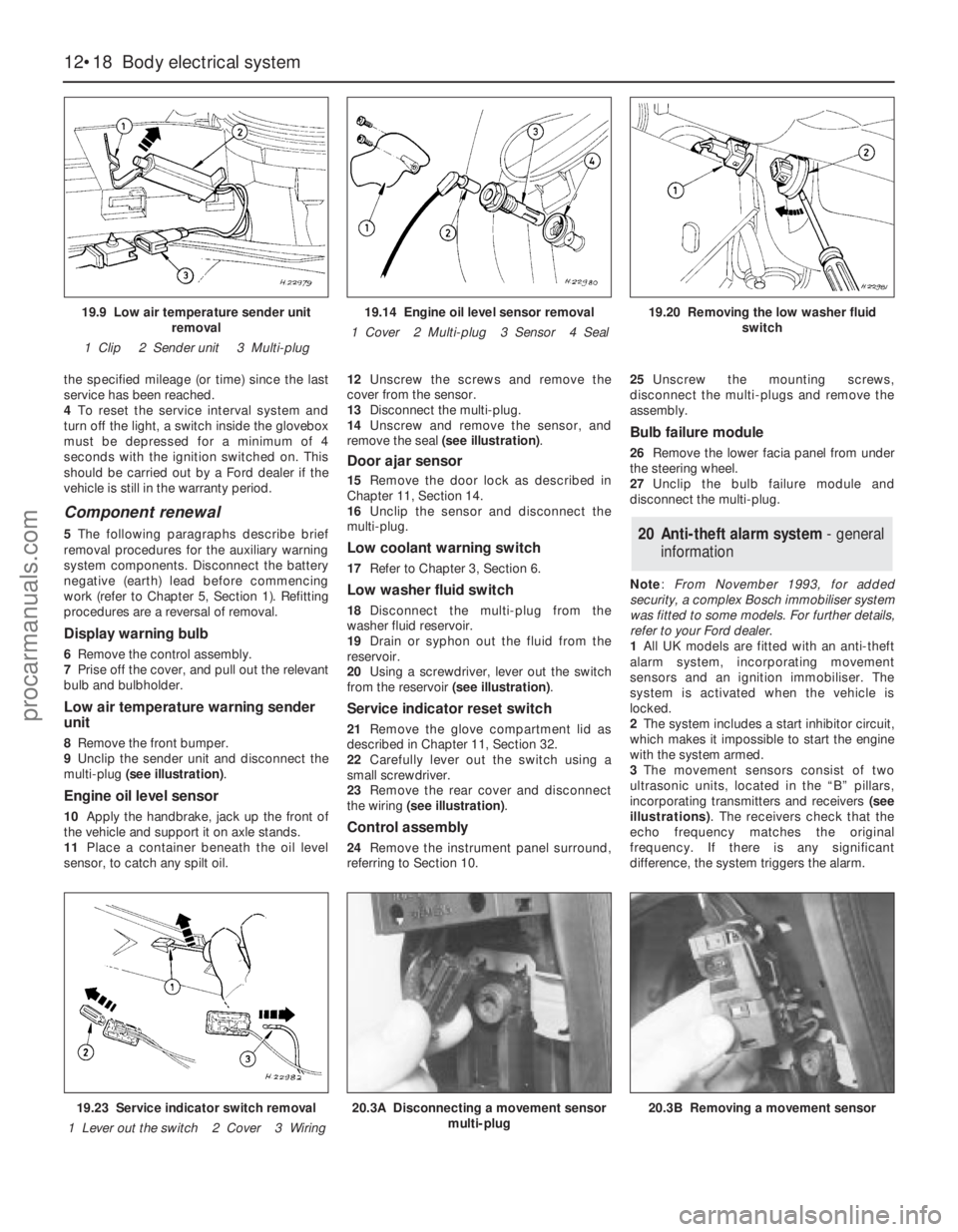
multi-plug (see illustration).
Engine oil level sensor
10Apply the handbrake, jack up the front of
the vehicle and support it on axle stands.
11Place a container beneath the oil level
sensor, to catch any spilt oil.12Unscrew the screws and remove the
cover from the sensor.
13Disconnect the multi-plug.
14Unscrew and remove the sensor, and
remove the seal (see illustration).
Door ajar sensor
15Remove the door lock as described in
Chapter 11, Section 14.
16Unclip the sensor and disconnect the
multi-plug.
Low coolant warning switch
17Refer to Chapter 3, Section 6.
Low washer fluid switch
18Disconnect the multi-plug from the
washer fluid reservoir.
19Drain or syphon out the fluid from the
reservoir.
20Using a screwdriver, lever out the switch
from the reservoir (see illustration).
Service indicator reset switch
21Remove the glove compartment lid as
described in Chapter 11, Section 32.
22Carefully lever out the switch using a
small screwdriver.
23Remove the rear cover and disconnect
the wiring (see illustration).
Control assembly
24Remove the instrument panel surround,
referring to Section 10.25Unscrew the mounting screws,
disconnect the multi-plugs and remove the
assembly.
Bulb failure module
26Remove the lower facia panel from under
the steering wheel.
27Unclip the bulb failure module and
disconnect the multi-plug.
Note: From November 1993, for added
security, a complex Bosch immobiliser system
was fitted to some models. For further details,
refer to your Ford dealer.
1All UK models are fitted with an anti-theft
alarm system, incorporating movement
sensors and an ignition immobiliser. The
system is activated when the vehicle is
locked.
2The system includes a start inhibitor circuit,
which makes it impossible to start the engine
with the system armed.
3The movement sensors consist of two
ultrasonic units, located in the “B” pillars,
incorporating transmitters and receivers (see
illustrations). The receivers check that the
echo frequency matches the original
frequency. If there is any significant
difference, the system triggers the alarm.
20 Anti-theft alarm system- general
information
12•18 Body electrical system
19.9 Low air temperature sender unit
removal
1 Clip 2 Sender unit 3 Multi-plug19.14 Engine oil level sensor removal
1 Cover 2 Multi-plug 3 Sensor 4 Seal19.20 Removing the low washer fluid
switch
19.23 Service indicator switch removal
1 Lever out the switch 2 Cover 3 Wiring20.3A Disconnecting a movement sensor
multi-plug20.3B Removing a movement sensor
procarmanuals.com
Page 263 of 279
REF•4
Whenever servicing, repair or overhaul work
is carried out on the car or its components, it
is necessary to observe the following
procedures and instructions. This will assist in
carrying out the operation efficiently and to a
professional standard of workmanship.
Joint mating faces and gaskets
When separating components at their
mating faces, never insert screwdrivers or
similar implements into the joint between the
faces in order to prise them apart. This can
cause severe damage which results in oil
leaks, coolant leaks, etc upon reassembly.
Separation is usually achieved by tapping
along the joint with a soft-faced hammer in
order to break the seal. However, note that
this method may not be suitable where
dowels are used for component location.
Where a gasket is used between the mating
faces of two components, ensure that it is
renewed on reassembly, and fit it dry unless
otherwise stated in the repair procedure.
Make sure that the mating faces are clean and
dry, with all traces of old gasket removed.
When cleaning a joint face, use a tool which is
not likely to score or damage the face, and
remove any burrs or nicks with an oilstone or
fine file.
Make sure that tapped holes are cleaned
with a pipe cleaner, and keep them free of
jointing compound, if this is being used,
unless specifically instructed otherwise.
Ensure that all orifices, channels or pipes
are clear, and blow through them, preferably
using compressed air.
Oil seals
Oil seals can be removed by levering them
out with a wide flat-bladed screwdriver or
similar implement. Alternatively, a number of
self-tapping screws may be screwed into the
seal, and these used as a purchase for pliers
or some similar device in order to pull the seal
free.
Whenever an oil seal is removed from its
working location, either individually or as part
of an assembly, it should be renewed.
The very fine sealing lip of the seal is easily
damaged, and will not seal if the surface it
contacts is not completely clean and free from
scratches, nicks or grooves.
Protect the lips of the seal from any surface
which may damage them in the course of
fitting. Use tape or a conical sleeve where
possible. Lubricate the seal lips with oil before
fitting and, on dual-lipped seals, fill the space
between the lips with grease.
Unless otherwise stated, oil seals must be
fitted with their sealing lips toward the
lubricant to be sealed.
Use a tubular drift or block of wood of the
appropriate size to install the seal and, if the
seal housing is shouldered, drive the seal
down to the shoulder. If the seal housing is
unshouldered, the seal should be fitted with
its face flush with the housing top face (unless
otherwise instructed).
Screw threads and fastenings
Seized nuts, bolts and screws are quite a
common occurrence where corrosion has set
in, and the use of penetrating oil or releasing
fluid will often overcome this problem if the
offending item is soaked for a while before
attempting to release it. The use of an impact
driver may also provide a means of releasing
such stubborn fastening devices, when used
in conjunction with the appropriate
screwdriver bit or socket. If none of these
methods works, it may be necessary to resort
to the careful application of heat, or the use of
a hacksaw or nut splitter device.
Studs are usually removed by locking two
nuts together on the threaded part, and then
using a spanner on the lower nut to unscrew
the stud. Studs or bolts which have broken off
below the surface of the component in which
they are mounted can sometimes be removed
using a proprietary stud extractor. Always
ensure that a blind tapped hole is completely
free from oil, grease, water or other fluid
before installing the bolt or stud. Failure to do
this could cause the housing to crack due to
the hydraulic action of the bolt or stud as it is
screwed in.
When tightening a castellated nut to accept
a split pin, tighten the nut to the specified
torque, where applicable, and then tighten
further to the next split pin hole. Never slacken
the nut to align the split pin hole, unless stated
in the repair procedure.
When checking or retightening a nut or bolt
to a specified torque setting, slacken the nut
or bolt by a quarter of a turn, and then
retighten to the specified setting. However,
this should not be attempted where angular
tightening has been used.
For some screw fastenings, notably cylinder
head bolts or nuts, torque wrench settings are
no longer specified for the latter stages of
tightening, “angle-tightening” being called up
instead. Typically, a fairly low torque wrench
setting will be applied to the bolts/nuts in
the correct sequence, followed by one or
more stages of tightening through specified
angles.
Locknuts, locktabs and washers
Any fastening which will rotate against a
component or housing in the course of
tightening should always have a washer
between it and the relevant component or
housing.
Spring or split washers should always be
renewed when they are used to lock a critical
component such as a big-end bearing
retaining bolt or nut. Locktabs which are
folded over to retain a nut or bolt should
always be renewed.
Self-locking nuts can be re-used in non-
critical areas, providing resistance can be felt
when the locking portion passes over the bolt
or stud thread. However, it should be noted
that self-locking stiffnuts tend to lose theireffectiveness after long periods of use, and in
such cases should be renewed as a matter of
course.
Split pins must always be replaced with
new ones of the correct size for the hole.
When thread-locking compound is found
on the threads of a fastener which is to be re-
used, it should be cleaned off with a wire
brush and solvent, and fresh compound
applied on reassembly.
Special tools
Some repair procedures in this manual
entail the use of special tools such as a press,
two or three-legged pullers, spring
compressors, etc. Wherever possible, suitable
readily-available alternatives to the
manufacturer’s special tools are described,
and are shown in use. Unless you are highly-
skilled and have a thorough understanding of
the procedures described, never attempt to
bypass the use of any special tool when the
procedure described specifies its use. Not
only is there a very great risk of personal
injury, but expensive damage could be
caused to the components involved.
Environmental considerations
When disposing of used engine oil, brake
fluid, antifreeze, etc, give due consideration to
any detrimental environmental effects. Do not,
for instance, pour any of the above liquids
down drains into the general sewage system,
or onto the ground to soak away. Many local
council refuse tips provide a facility for waste
oil disposal, as do some garages. If none of
these facilities are available, consult your local
Environmental Health Department for further
advice.
With the universal tightening-up of
legislation regarding the emission of
environmentally-harmful substances from
motor vehicles, most current vehicles have
tamperproof devices fitted to the main
adjustment points of the fuel system. These
devices are primarily designed to prevent
unqualified persons from adjusting the fuel/air
mixture, with the chance of a consequent
increase in toxic emissions. If such devices
are encountered during servicing or overhaul,
they should, wherever possible, be renewed
or refitted in accordance with the vehicle
manufacturer’s requirements or current
legislation.
Note: It is
antisocial and
illegal to dump
oil down the
drain. To find
the location of
your local oil
recycling
bank, call this
number free.
General Repair Procedures
procarmanuals.com
Page 265 of 279
REF•6Fault Finding
Engine 1
m mEngine backfires
m mEngine difficult to start when cold
m mEngine difficult to start when hot
m mEngine fails to rotate when attempting to start
m mEngine hesitates on acceleration
m mEngine idles erratically
m mEngine lacks power
m mEngine misfires at idle speed
m mEngine misfires throughout the driving speed range
m mEngine noises
m mEngine rotates but will not start
m mEngine runs-on after switching off
m mEngine stalls
m mEngine starts but stops immediately
m mOil pressure warning light illuminated with engine running
m mStarter motor noisy or excessively-rough in engagement
Cooling system 2
m
mCorrosion
m mExternal coolant leakage
m mInternal coolant leakage
m mOvercooling
m mOverheating
Fuel and exhaust systems 3
m
mExcessive fuel consumption
m mExcessive noise or fumes from exhaust system
m mFuel leakage and/or fuel odour
Clutch 4
m
mClutch fails to disengage (unable to select gears)
m mClutch slips (engine speed increases with no increase
in vehicle speed)
m mJudder as clutch is engaged
m mNoise when depressing or releasing clutch pedal
m mPedal travels to floor - no pressure or very little resistance
Manual transmission 5
m
mJumps out of gear
m mLubricant leaks
m mNoisy in neutral with engine running
m mNoisy in one particular gear
m mVibration
Automatic transmission 6
m
mEngine will not start in any gear, or starts in gears
other than Park or Neutral
m mFluid leakage
m mGeneral gear selection problems
m mTransmission fluid brown, or has burned smell
m mTransmission slips, shifts roughly, is noisy, or
has no drive in forward or reverse gears
m mTransmission will not downshift (kickdown) with
accelerator fully depressed
Driveshafts 7
m mClicking or knocking noise on turns (at slow speed on full-lock)
m mVibration when accelerating or decelerating
Braking system 8
m
mBrake pedal feels spongy when depressed
m mBrakes binding
m mExcessive brake pedal effort required to stop vehicle
m mExcessive brake pedal travel
m mJudder felt through brake pedal or steering wheel when braking
m mNoise (grinding or high-pitched squeal) when brakes applied
m mRear wheels locking under normal braking
m mVehicle pulls to one side under braking
Suspension and steering systems 9
m
mExcessive pitching and/or rolling around corners, or during
braking
m mExcessive play in steering
m mExcessively-stiff steering
m mLack of power assistance
m mTyre wear excessive
m mVehicle pulls to one side
m mWandering or general instability
m mWheel wobble and vibration
Electrical system 10
m
mBattery will not hold a charge for more than a few days
m mCentral locking system inoperative, or unsatisfactory in operation
m mElectric windows inoperative, or unsatisfactory in operation
m mHorn inoperative, or unsatisfactory in operation
m mIgnition warning light fails to come on
m mIgnition warning light remains illuminated with engine running
m mInstrument readings inaccurate or erratic
m mLights inoperative
m mWindscreen/tailgate washers inoperative, or unsatisfactory in
operation
m mWindscreen/tailgate wipers inoperative, or unsatisfactory in
operation
procarmanuals.com
Page 267 of 279
Engine misfires throughout the driving speed range
m mFuel filter choked (Chapter 1).
m mFuel pump faulty or delivery pressure low (Chapter 4).
m mFuel tank vent blocked or fuel pipes restricted (Chapter 4).
m mVacuum leak at the inlet manifold or associated hoses (Chap-
ters 1, 4 and 6).
m mWorn, faulty or incorrectly-gapped spark plugs (Chapter 1).
m mFaulty spark plug HT leads (Chapter 1).
m mFaulty ignition coil (Chapter 5).
m mEngine management system fault (Chapters 1, 4, 5 and 6)
m mUneven or low cylinder compressions (Chapter 2, Part A).
Engine hesitates on acceleration
m
mWorn, faulty or incorrectly-gapped spark plugs (Chapter 1).
m mEngine management system fault (Chapters 1, 4, 5 and 6).
m mVacuum leak at the inlet manifold or associated hoses (Chap-
ters 1, 4 and 6).
Engine stalls
m mIdle speed control valve faulty (Chapter 4).
m mEngine management system fault (Chapters 1, 4, 5 and 6).
m mVacuum leak at the inlet manifold or associated hoses (Chap-
ters 1, 4 and 6).
m mFuel filter choked (Chapter 1).
m mFuel pump faulty or delivery pressure low (Chapter 4).
m mFuel tank vent blocked or fuel pipes restricted (Chapter 4).
Engine lacks power
m
mIncorrect ignition timing (Chapters 5 and 6).
m mEngine management system fault (Chapters 1, 4, 5 and 6).
m mTiming belt incorrectly fitted or incorrectly tensioned (Chapter 2,
Part A).
m mFuel filter choked (Chapter 1).
m mFuel pump faulty or delivery pressure low (Chapter 4).
m mUneven or low cylinder compressions (Chapter 2, Part A).
m mWorn, faulty or incorrectly-gapped spark plugs (Chapter 1).
m mVacuum leak at the inlet manifold or associated hoses (Chap-
ters 1, 4 and 6).
m mBrakes binding (Chapters 1 and 9).
m mClutch slipping (Chapter 8).
m mAutomatic transmission fluid level incorrect (Chapter 1).
Engine runs-on after switching off
m
mIdle speed excessively high (Chapters 4 and 6).
m mEngine management system fault (Chapters 1, 4, 5 and 6).
m mExcessive carbon build-up in engine (Chapter 2, Part A).
m mHigh engine operating temperature (Chapter 3).
Engine backfires
m
mIgnition timing incorrect (Chapters 5 and 6).
m mEngine management system fault (Chapters 1, 4, 5 and 6).
m mTiming belt incorrectly fitted or incorrectly tensioned (Chapter 2,
Part A).
m mVacuum leak at the inlet manifold or associated hoses (Chap-
ters 1, 4 and 6).
Oil pressure warning light illuminated with engine
running
m mLow oil level or incorrect oil grade (Chapter 1).
m mFaulty oil pressure warning light switch (Chapter 2, Part A).
m mWorn engine bearings and/or oil pump (Chapter 2).
m mHigh engine operating temperature (Chapter 3).
m mOil pressure relief valve defective (Chapter 2, Part A).
m mOil pick-up strainer clogged (Chapter 2, Part A).
Engine noises
Pre-ignition (pinking) or knocking during acceleration or under
load
m mIgnition timing incorrect (Chapters 5 and 6).
m mIncorrect grade of fuel (Chapter 4).
m mVacuum leak at the inlet manifold or associated hoses (Chap-
ters 1, 4 and 6).
m mExcessive carbon build-up in engine (Chapter 2, Part A).
Whistling or wheezing noises
m mLeaking inlet manifold gasket (Chapter 2, Part A).
m mLeaking exhaust manifold gasket or downpipe-to-manifold joint
(Chapters 1, 2 Part A, and 4).
m mLeaking vacuum hose (Chapters 1, 4, 6 and 9).
m mBlowing cylinder head gasket (Chapter 2, Part A).
Tapping or rattling noises
m mFaulty hydraulic tappet(s) (Chapter 2, Part A).
m mWorn valve gear or camshaft (Chapter 2, Part A).
m mWorn timing belt or tensioner (Chapter 2, Part A).
m mAncillary component fault (water pump, alternator, etc) (Chap-
ters 3 and 5).
Knocking or thumping noises
m mWorn big-end bearings (regular heavy knocking, perhaps less
under load) (Chapter 2, Part B).
m mWorn main bearings (rumbling and knocking, perhaps worsening
under load) (Chapter 2, Part B).
m mPiston slap (most noticeable when cold) (Chapter 2, Part B).
m mAncillary component fault (water pump, alternator, etc) (Chap-
ters 3 and 5).
REF•8Fault Finding
2 Cooling system
Overheating
m mInsufficient coolant in system (Chapter 1).
m mThermostat faulty (Chapter 3).
m mRadiator core blocked or grille restricted (Chapter 3).
m mRadiator electric cooling fan(s) or coolant temperature sensor faulty
(Chapter 3).
m mEngine management system fault (Chapters 1, 4, 5 and 6).
m mPressure cap faulty (Chapter 3).
m mAuxiliary drivebelt worn or slipping (Chapter 1).
m mIgnition timing incorrect (Chapters 5 and 6).
m mInaccurate coolant temperature gauge sender (Chapter 3).
m mAir-lock in cooling system (Chapter 1).
Overcooling
m
mThermostat faulty (Chapter 3).
m mInaccurate coolant temperature gauge sender (Chapter 3).
External coolant leakage
m
mDeteriorated or damaged hoses or hose clips (Chapter 1).
m mRadiator core or heater matrix leaking (Chapter 3).
m mPressure cap faulty (Chapter 3).
m mWater pump seal leaking (Chapter 3).
m mBoiling due to overheating (Chapter 3).
m mCore plug leaking (Chapter 2, Part B).
procarmanuals.com