1993 FORD MONDEO low oil pressure
[x] Cancel search: low oil pressurePage 56 of 279
away from the gauge, and note the gauge
reading. If the endfloat measured is found to
be at or beyond the specified service limit, fit
a new camshaft and repeat the check; if the
clearance is still excessive, the cylinder head
must be renewed.
Refitting
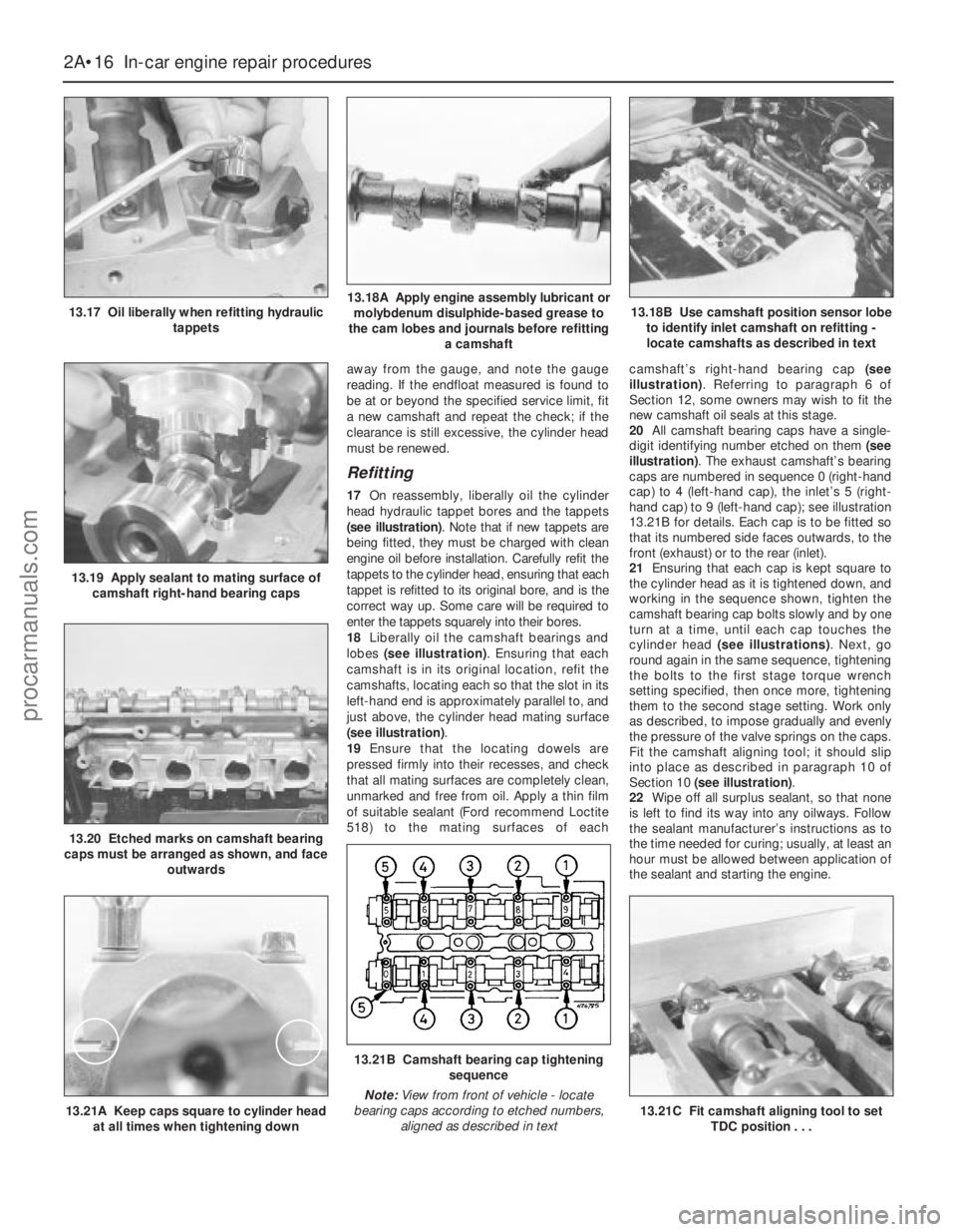
17On reassembly, liberally oil the cylinder
head hydraulic tappet bores and the tappets
(see illustration). Note that if new tappets are
being fitted, they must be charged with clean
engine oil before installation. Carefully refit the
tappets to the cylinder head, ensuring that each
tappet is refitted to its original bore, and is the
correct way up. Some care will be required to
enter the tappets squarely into their bores.
18Liberally oil the camshaft bearings and
lobes (see illustration). Ensuring that each
camshaft is in its original location, refit the
camshafts, locating each so that the slot in its
left-hand end is approximately parallel to, and
just above, the cylinder head mating surface
(see illustration).
19Ensure that the locating dowels are
pressed firmly into their recesses, and check
that all mating surfaces are completely clean,
unmarked and free from oil. Apply a thin film
of suitable sealant (Ford recommend Loctite
518) to the mating surfaces of eachcamshaft’s right-hand bearing cap (see
illustration). Referring to paragraph 6 of
Section 12, some owners may wish to fit the
new camshaft oil seals at this stage.
20All camshaft bearing caps have a single-
digit identifying number etched on them (see
illustration). The exhaust camshaft’s bearing
caps are numbered in sequence 0 (right-hand
cap) to 4 (left-hand cap), the inlet’s 5 (right-
hand cap) to 9 (left-hand cap); see illustration
13.21B for details. Each cap is to be fitted so
that its numbered side faces outwards, to the
front (exhaust) or to the rear (inlet).
21Ensuring that each cap is kept square to
the cylinder head as it is tightened down, and
working in the sequence shown, tighten the
camshaft bearing cap bolts slowly and by one
turn at a time, until each cap touches the
cylinder head (see illustrations). Next, go
round again in the same sequence, tightening
the bolts to the first stage torque wrench
setting specified, then once more, tightening
them to the second stage setting. Work only
as described, to impose gradually and evenly
the pressure of the valve springs on the caps.
Fit the camshaft aligning tool; it should slip
into place as described in paragraph 10 of
Section 10 (see illustration).
22Wipe off all surplus sealant, so that none
is left to find its way into any oilways. Follow
the sealant manufacturer’s instructions as to
the time needed for curing; usually, at least an
hour must be allowed between application of
the sealant and starting the engine.
2A•16 In-car engine repair procedures
13.17 Oil liberally when refitting hydraulic
tappets13.18A Apply engine assembly lubricant or
molybdenum disulphide-based grease to
the cam lobes and journals before refitting
a camshaft
13.19 Apply sealant to mating surface of
camshaft right-hand bearing caps
13.20 Etched marks on camshaft bearing
caps must be arranged as shown, and face
outwards
13.18B Use camshaft position sensor lobe
to identify inlet camshaft on refitting -
locate camshafts as described in text
13.21A Keep caps square to cylinder head
at all times when tightening down
13.21B Camshaft bearing cap tightening
sequence
Note:View from front of vehicle - locate
bearing caps according to etched numbers,
aligned as described in text
13.21C Fit camshaft aligning tool to set
TDC position . . .
procarmanuals.com
Page 57 of 279
23If using Ford’s recommended procedure,
fit new oil seals to the camshafts as
described in paragraph 5 of Section 12.
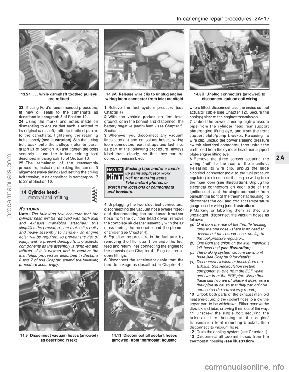
24Using the marks and notes made on
dismantling to ensure that each is refitted to
its original camshaft, refit the toothed pulleys
to the camshafts, tightening the retaining
bolts loosely (see illustration). Slip the timing
belt back onto the pulleys (refer to para-
graph 21 of Section 10) and tighten the bolts
securely - use the forked holding tool
described in paragraph 18 of Section 10.
25The remainder of the reassembly
procedure, including checking the camshaft
alignment (valve timing) and setting the timing
belt tension, is as described in paragraphs 17
to 27 of Section 10.
Removal
Note:The following text assumes that the
cylinder head will be removed with both inlet
and exhaust manifolds attached; this
simplifies the procedure, but makes it a bulky
and heavy assembly to handle - an engine
hoist will be required, to prevent the risk of
injury, and to prevent damage to any delicate
components as the assembly is removed and
refitted. If it is wished first to remove the
manifolds, proceed as described in Sections
6 and 7 of this Chapter; amend the following
procedure accordingly.1Relieve the fuel system pressure (see
Chapter 4).
2With the vehicle parked on firm level
ground, open the bonnet and disconnect the
battery negative (earth) lead - see Chapter 5,
Section 1.
3Whenever you disconnect any vacuum
lines, coolant and emissions hoses, wiring
loom connectors, earth straps and fuel lines
as part of the following procedure, always
label them clearly, so that they can be
correctly reassembled.
4Unplugging the two electrical connectors,
disconnecting the vacuum hose (where fitted)
and disconnecting the crankcase breather
hose from the cylinder head cover, remove
the complete air cleaner assembly with the air
mass meter, the resonator and the plenum
chamber (see Chapter 4).
5Equalise the pressure in the fuel tank by
removing the filler cap, then undo the fuel
feed and return lines connecting the engine to
the chassis (see Chapter 4). Plug or cap all
open fittings.
6Disconnect the accelerator cable from the
throttle linkage as described in Chapter 4 -where fitted, disconnect also the cruise control
actuator cable (see Chapter 12). Secure the
cable(s) clear of the engine/transmission.
7Unbolt the power steering high-pressure
pipe from the cylinder head rear support
plate/engine lifting eye, and from the front
support plate/pump bracket. Releasing its
wire clip, unplug the power steering pressure
switch electrical connector, then unbolt the
earth lead from the cylinder head rear support
plate/engine lifting eye.
8Remove the three screws securing the
wiring “rail” to the rear of the manifold.
Releasing its wire clip, unplug the large
electrical connector (next to the fuel pressure
regulator) to disconnect the engine wiring from
the main loom (see illustration). Unplug the
electrical connectors on each side of the
ignition coil, and the single connector from
beneath the front of the thermostat housing, to
disconnect the coil and coolant temperature
gauge sender wiring (see illustration).
9Marking or labelling them as they are
unplugged, disconnect the vacuum hoses as
follows:
(a) One from the rear of the throttle housing
(only the one hose - there is no need to
disconnect the second hose running to
the fuel pressure regulator).
(b) One from the union on the inlet manifold’s
left-hand end (see illustration).
(c) The braking system vacuum servo unit
hose (see Chapter 9 for details).
(d) Disconnect all vacuum hoses from the
Exhaust Gas Recirculation system
components - one from the EGR valve
and two from the EGR pipe. (Note that
these last two are of different sizes, as are
their pipe stubs, so that they can only be
connected the correct way round.)
10Unbolt both parts of the exhaust manifold
heat shield; unclip the coolant hose to allow the
upper part to be withdrawn. Either remove the
dipstick and tube, or swing them out of the way.
11Unscrew the single bolt securing the
pulse-air filter housing to the engine/
transmission front mounting bracket, then
disconnect its vacuum hose.
12Drain the cooling system (see Chapter 1).
13Disconnect all coolant hoses from the
thermostat housing (see illustration).
14 Cylinder head -
removal and refitting
In-car engine repair procedures 2A•17
2A
14.9 Disconnect vacuum hoses (arrowed)
as described in text14.13 Disconnect all coolant hoses
(arrowed) from thermostat housing
13.24 . . . while camshaft toothed pulleys
are refitted14.8A Release wire clip to unplug engine
wiring loom connector from inlet manifold14.8B Unplug connectors (arrowed) to
disconnect ignition coil wiring
Masking tape and/or a touch-
up paint applicator work
well for marking items.
Take instant photos, or
sketch the locations of components
and brackets.
procarmanuals.com
Page 61 of 279
and right-hand mountings. Do not yet
release the hoist; the weight of the
engine/transmission unit must not be
taken by the mountings until all are
correctly aligned.
(d) Fitting the Ford service tool in place of the
front mounting, tighten the
engine/transmission mounting fasteners
to their specified torque wrench settings,
and in the sequence described in Part B
of this Chapter, Section 4, paragraphs 49
and 50.
(e) Refill the cooling system (see Chapter 1).
(f) Refill the engine with oil, remembering
that you are advised to fit a new filter (see
Chapter 1).
(g) Check for signs of oil or coolant leaks
once the engine has been restarted and
warmed-up to normal operating
temperature.
Removal
Note:While this task is theoretically possible
when the engine is in place in the vehicle, in
practice, it requires so much preliminary
dismantling, and is so difficult to carry out due
to the restricted access, that owners are
advised to remove the engine from the vehicle
first. Note, however, that the oil pumppressure relief valve can be removed with the
engine in situ - see paragraph 8.
In addition to the new pump gasket and
other replacement parts required, read
through Section 15, and ensure that the
necessary tools and facilities are available.
1Remove the timing belt (see Section 10).
2Withdraw the crankshaft toothed pulley
and the thrustwasher behind it, noting which
way round the thrustwasher is fitted (see
Section 11).
3Remove the sump (see Section 15).
4Undo the screws securing the oil pump
pick-up/strainer pipe to the pump, then
unscrew the nut and withdraw the oil pump
pick-up/strainer pipe. Discard the gasket.
5Unbolt the pump from the cylinder
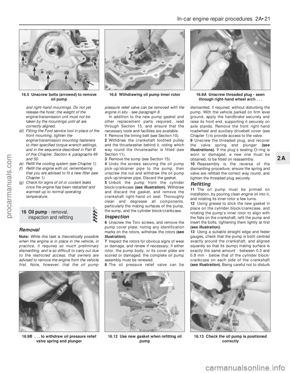
block/crankcase (see illustration). Withdraw
and discard the gasket, and remove the
crankshaft right-hand oil seal. Thoroughly
clean and degrease all components,
particularly the mating surfaces of the pump,
the sump, and the cylinder block/crankcase.
Inspection
6Unscrew the Torx screws, and remove the
pump cover plate; noting any identification
marks on the rotors, withdraw the rotors (see
illustration).
7Inspect the rotors for obvious signs of wear
or damage, and renew if necessary; if either
rotor, the pump body, or its cover plate are
scored or damaged, the complete oil pump
assembly must be renewed.
8The oil pressure relief valve can bedismantled, if required, without disturbing the
pump. With the vehicle parked on firm level
ground, apply the handbrake securely and
raise its front end, supporting it securely on
axle stands. Remove the front right-hand
roadwheel and auxiliary drivebelt cover (see
Chapter 1) to provide access to the valve.
9Unscrew the threaded plug, and recover
the valve spring and plunger (see
illustrations). If the plug’s sealing O-ring is
worn or damaged, a new one must be
obtained, to be fitted on reassembly.
10Reassembly is the reverse of the
dismantling procedure; ensure the spring and
valve are refitted the correct way round, and
tighten the threaded plug securely.
Refitting
11The oil pump must be primed on
installation, by pouring clean engine oil into it,
and rotating its inner rotor a few turns.
12Using grease to stick the new gasket in
place on the cylinder block/crankcase, and
rotating the pump’s inner rotor to align with
the flats on the crankshaft, refit the pump and
insert the bolts, tightening them lightly at first
(see illustration).
13Using a suitable straight edge and feeler
gauges, check that the pump is both centred
exactlyaround the crankshaft, and aligned
squarely so that its (sump) mating surface is
exactly the same amount - between 0.3 and
0.8 mm - below that of the cylinder block/
crankcase on each side of the crankshaft
(see illustration). Being careful not to disturb
16 Oil pump - removal,
inspection and refitting
In-car engine repair procedures 2A•21
2A
16.9B . . . to withdraw oil pressure relief
valve spring and plunger16.12 Use new gasket when refitting oil
pump16.13 Check the oil pump is positioned
correctly
16.5 Unscrew bolts (arrowed) to remove
oil pump16.6 Withdrawing oil pump inner rotor16.9A Unscrew threaded plug - seen
through right-hand wheel arch . . .
procarmanuals.com
Page 62 of 279
the gasket, move the pump into the correct
position, and tighten its bolts to the specified
torque wrench setting.
14Check that the pump is correctly located;
if necessary, unbolt it again, and repeat the
full procedure to ensure that the pump is
correctly aligned.
15Fit a new crankshaft right-hand oil seal
(see Section 20).
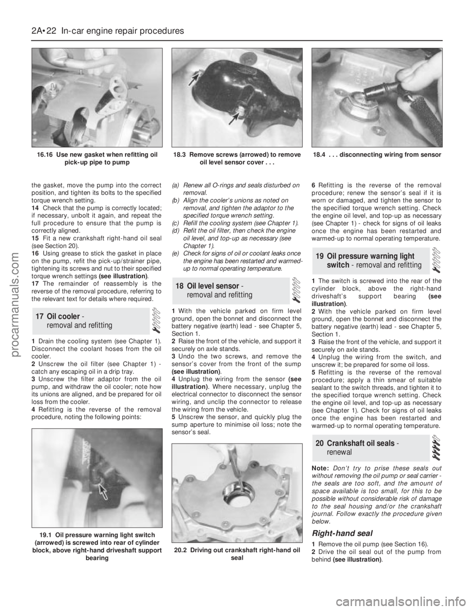
16Using grease to stick the gasket in place
on the pump, refit the pick-up/strainer pipe,
tightening its screws and nut to their specified
torque wrench settings (see illustration).
17The remainder of reassembly is the
reverse of the removal procedure, referring to
the relevant text for details where required.
1Drain the cooling system (see Chapter 1).
Disconnect the coolant hoses from the oil
cooler.
2Unscrew the oil filter (see Chapter 1) -
catch any escaping oil in a drip tray.
3Unscrew the filter adaptor from the oil
pump, and withdraw the oil cooler; note how
its unions are aligned, and be prepared for oil
loss from the cooler.
4Refitting is the reverse of the removal
procedure, noting the following points:(a) Renew all O-rings and seals disturbed on
removal.
(b) Align the cooler’s unions as noted on
removal, and tighten the adaptor to the
specified torque wrench setting.
(c) Refill the cooling system (see Chapter 1).
(d) Refit the oil filter, then check the engine
oil level, and top-up as necessary (see
Chapter 1).
(e) Check for signs of oil or coolant leaks once
the engine has been restarted and warmed-
up to normal operating temperature.
1With the vehicle parked on firm level
ground, open the bonnet and disconnect the
battery negative (earth) lead - see Chapter 5,
Section 1.
2Raise the front of the vehicle, and support it
securely on axle stands.
3Undo the two screws, and remove the
sensor’s cover from the front of the sump
(see illustration).
4Unplug the wiring from the sensor (see
illustration). Where necessary, unplug the
electrical connector to disconnect the sensor
wiring, and unclip the connector to release
the wiring from the vehicle.
5Unscrew the sensor, and quickly plug the
sump aperture to minimise oil loss; note the
sensor’s seal.6Refitting is the reverse of the removal
procedure; renew the sensor’s seal if it is
worn or damaged, and tighten the sensor to
the specified torque wrench setting. Check
the engine oil level, and top-up as necessary
(see Chapter 1) - check for signs of oil leaks
once the engine has been restarted and
warmed-up to normal operating temperature.
1The switch is screwed into the rear of the
cylinder block, above the right-hand
driveshaft’s support bearing (see
illustration).
2With the vehicle parked on firm level
ground, open the bonnet and disconnect the
battery negative (earth) lead - see Chapter 5,
Section 1.
3Raise the front of the vehicle, and support it
securely on axle stands.
4Unplug the wiring from the switch, and
unscrew it; be prepared for some oil loss.
5Refitting is the reverse of the removal
procedure; apply a thin smear of suitable
sealant to the switch threads, and tighten it to
the specified torque wrench setting. Check
the engine oil level, and top-up as necessary
(see Chapter 1). Check for signs of oil leaks
once the engine has been restarted and
warmed-up to normal operating temperature.
Note:Don’t try to prise these seals out
without removing the oil pump or seal carrier -
the seals are too soft, and the amount of
space available is too small, for this to be
possible without considerable risk of damage
to the seal housing and/or the crankshaft
journal. Follow exactly the procedure given
below.
Right-hand seal
1Remove the oil pump (see Section 16).
2Drive the oil seal out of the pump from
behind (see illustration).
20 Crankshaft oil seals -
renewal
19 Oil pressure warning light
switch - removal and refitting
18 Oil level sensor-
removal and refitting
17 Oil cooler -
removal and refitting
2A•22 In-car engine repair procedures
16.16 Use new gasket when refitting oil
pick-up pipe to pump18.3 Remove screws (arrowed) to remove
oil level sensor cover . . .18.4 . . . disconnecting wiring from sensor
19.1 Oil pressure warning light switch
(arrowed) is screwed into rear of cylinder
block, above right-hand driveshaft support
bearing
20.2 Driving out crankshaft right-hand oil
seal
procarmanuals.com
Page 70 of 279
safely and with relative ease, and which may
have to be hired or borrowed, includes (in
addition to the engine hoist) a heavy-duty trolley
jack, a strong pair of axle stands, some wooden
blocks, and an engine dolly (a low, wheeled
platform capable of taking the weight of the
engine/transmission, so that it can be moved
easily when on the ground). A complete set of
spanners and sockets (as described in the front
of this manual) will obviously be needed,
together with plenty of rags and cleaning
solvent for mopping-up spilled oil, coolant and
fuel. If the hoist is to be hired, make sure that
you arrange for it in advance, and perform all of
the operations possible without it beforehand.
This will save you money and time.
Plan for the vehicle to be out of use for
quite a while. A machine shop will be required
to perform some of the work which the do-it-
yourselfer can’t accomplish without special
equipment. These establishments often have
a busy schedule, so it would be a good idea
to consult them before removing the engine,
to accurately estimate the amount of time
required to rebuild or repair components that
may need work.
Always be extremely careful when removing
and installing the engine/transmission.
Serious injury can result from careless
actions. By planning ahead and taking your
time, the job (although a major task) can be
accomplished successfully.
Warning: Petrol is extremely
flammable, so take extra
precautions when disconnecting
any part of the fuel system. Don’t
smoke, or allow naked flames or bare light
bulbs in or near the work area, and don’t
work in a garage where a natural gas
appliance (such as a clothes dryer or water
heater) is installed. If you spill petrol on
your skin, rinse it off immediately. Have a
fire extinguisher rated for petrol fires
handy, and know how to use it.Note: Read through the entire Section, as well
as reading the advice in the preceding Section,
before beginning this procedure. The engine
and transmission are removed as a unit,
lowered to the ground and removed from
underneath, then separated outside the vehicle.
Removal
1Park the vehicle on firm, level ground, apply
the handbrake firmly, and slacken the nuts
securing both front roadwheels.
2Relieve the fuel system pressure (see
Chapter 4).
3Disconnect the battery negative (earth) lead
- see Chapter 5, Section 1. For better access
the battery may be removed completely (see
Chapter 5).
4Place protective covers on the wings and
engine compartment front crossmember, then
remove the bonnet (see Chapter 11).
5Whenever you disconnect any vacuum
lines, coolant and emissions hoses, wiring
loom connectors, earth straps and fuel lines
as part of the following procedure, always
label them clearly, so that they can be
correctly reassembled.
6Unplug the two electrical connectors,disconnect the vacuum hose (where fitted)
and disconnect the crankcase breather hose
from the cylinder head cover, then remove the
complete air cleaner assembly, with the air
mass meter, the resonator and the plenum
chamber (see Chapter 4).
7Equalise the pressure in the fuel tank by
removing the filler cap, then undo the fuel
feed and return lines connecting the engine to
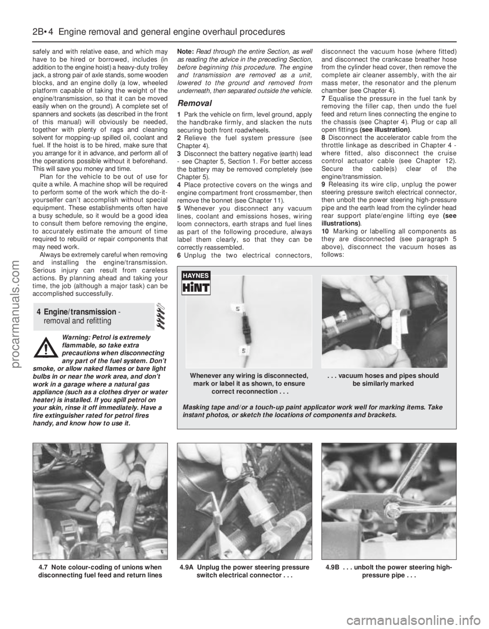
the chassis (see Chapter 4). Plug or cap all
open fittings (see illustration).
8Disconnect the accelerator cable from the
throttle linkage as described in Chapter 4 -
where fitted, also disconnect the cruise
control actuator cable (see Chapter 12).
Secure the cable(s) clear of the
engine/transmission.
9Releasing its wire clip, unplug the power
steering pressure switch electrical connector,
then unbolt the power steering high-pressure
pipe and the earth lead from the cylinder head
rear support plate/engine lifting eye (see
illustrations).
10Marking or labelling all components as
they are disconnected (see paragraph 5
above), disconnect the vacuum hoses as
follows:
4 Engine/transmission -
removal and refitting
2B•4 Engine removal and general engine overhaul procedures
4.7 Note colour-coding of unions when
disconnecting fuel feed and return lines4.9A Unplug the power steering pressure
switch electrical connector . . .4.9B . . . unbolt the power steering high-
pressure pipe . . .
Whenever any wiring is disconnected, . . . vacuum hoses and pipes should
mark or label it as shown, to ensure be similarly marked
correct reconnection . . .
Masking tape and/or a touch-up paint applicator work well for marking items. Take
instant photos, or sketch the locations of components and brackets.
procarmanuals.com
Page 71 of 279
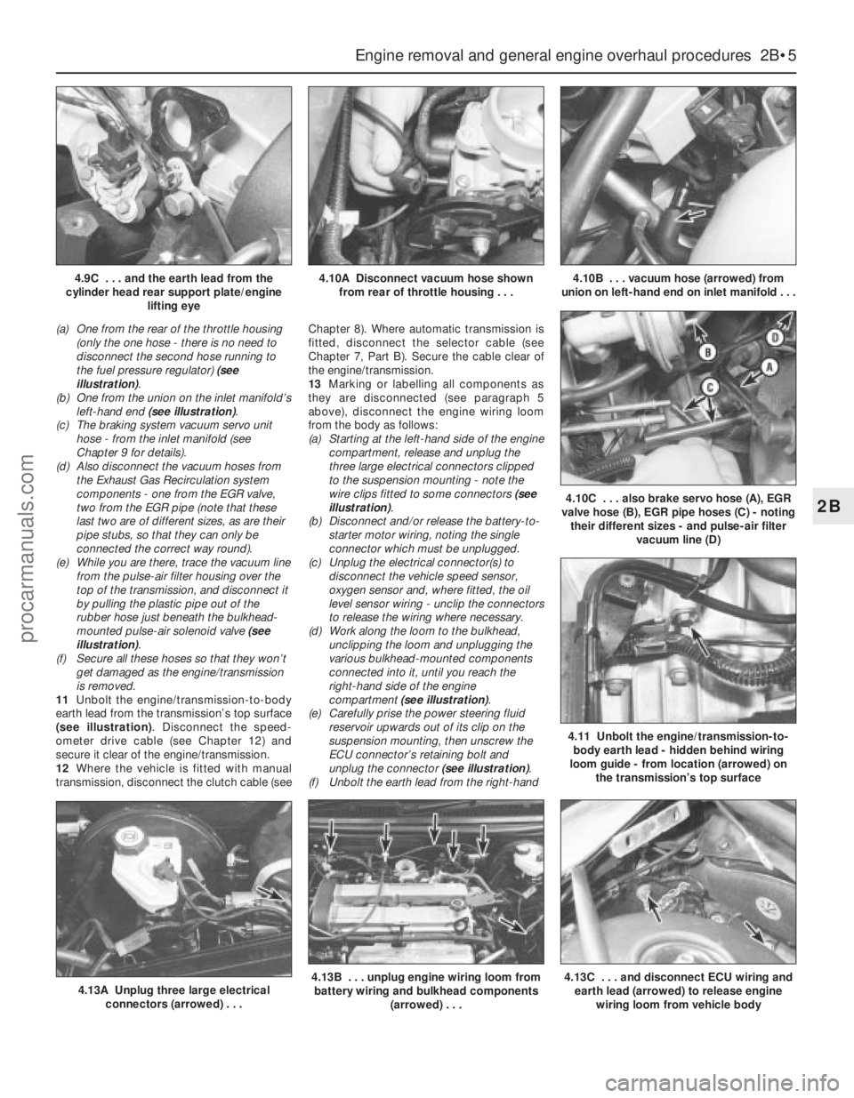
(a) One from the rear of the throttle housing
(only the one hose - there is no need to
disconnect the second hose running to
the fuel pressure regulator) (see
illustration).
(b) One from the union on the inlet manifold’s
left-hand end (see illustration).
(c) The braking system vacuum servo unit
hose - from the inlet manifold (see
Chapter 9 for details).
(d) Also disconnect the vacuum hoses from
the Exhaust Gas Recirculation system
components - one from the EGR valve,
two from the EGR pipe (note that these
last two are of different sizes, as are their
pipe stubs, so that they can only be
connected the correct way round).
(e) While you are there, trace the vacuum line
from the pulse-air filter housing over the
top of the transmission, and disconnect it
by pulling the plastic pipe out of the
rubber hose just beneath the bulkhead-
mounted pulse-air solenoid valve (see
illustration).
(f) Secure all these hoses so that they won’t
get damaged as the engine/transmission
is removed.
11Unbolt the engine/transmission-to-body
earth lead from the transmission’s top surface
(see illustration). Disconnect the speed-
ometer drive cable (see Chapter 12) and
secure it clear of the engine/transmission.
12Where the vehicle is fitted with manual
transmission, disconnect the clutch cable (seeChapter 8). Where automatic transmission is
fitted, disconnect the selector cable (see
Chapter 7, Part B). Secure the cable clear of
the engine/transmission.
13Marking or labelling all components as
they are disconnected (see paragraph 5
above), disconnect the engine wiring loom
from the body as follows:
(a) Starting at the left-hand side of the engine
compartment, release and unplug the
three large electrical connectors clipped
to the suspension mounting - note the
wire clips fitted to some connectors (see
illustration).
(b) Disconnect and/or release the battery-to-
starter motor wiring, noting the single
connector which must be unplugged.
(c) Unplug the electrical connector(s) to
disconnect the vehicle speed sensor,
oxygen sensor and, where fitted, the oil
level sensor wiring - unclip the connectors
to release the wiring where necessary.
(d) Work along the loom to the bulkhead,
unclipping the loom and unplugging the
various bulkhead-mounted components
connected into it, until you reach the
right-hand side of the engine
compartment (see illustration).
(e) Carefully prise the power steering fluid
reservoir upwards out of its clip on the
suspension mounting, then unscrew the
ECU connector’s retaining bolt and
unplug the connector (see illustration).
(f) Unbolt the earth lead from the right-hand
Engine removal and general engine overhaul procedures 2B•5
2B
4.13A Unplug three large electrical
connectors (arrowed) . . .4.13B . . . unplug engine wiring loom from
battery wiring and bulkhead components
(arrowed) . . .4.13C . . . and disconnect ECU wiring and
earth lead (arrowed) to release engine
wiring loom from vehicle body
4.9C . . . and the earth lead from the
cylinder head rear support plate/engine
lifting eye4.10A Disconnect vacuum hose shown
from rear of throttle housing . . .4.10B . . . vacuum hose (arrowed) from
union on left-hand end on inlet manifold . . .
4.10C . . . also brake servo hose (A), EGR
valve hose (B), EGR pipe hoses (C) - noting
their different sizes - and pulse-air filter
vacuum line (D)
4.11 Unbolt the engine/transmission-to-
body earth lead - hidden behind wiring
loom guide - from location (arrowed) on
the transmission’s top surface
procarmanuals.com
Page 78 of 279
grinding or head resurfacing. Use
compressed air, if available, to blow out all the
oil holes and passages.
2Beginning at one end of the head, lubricate
and install the first valve. Apply molybdenum
disulphide-based grease or clean engine oil to
the valve stem, and refit the valve. Where the
original valves are being re-used, ensure that
each is refitted in its original guide. If new
valves are being fitted, insert them into the
locations to which they have been ground.
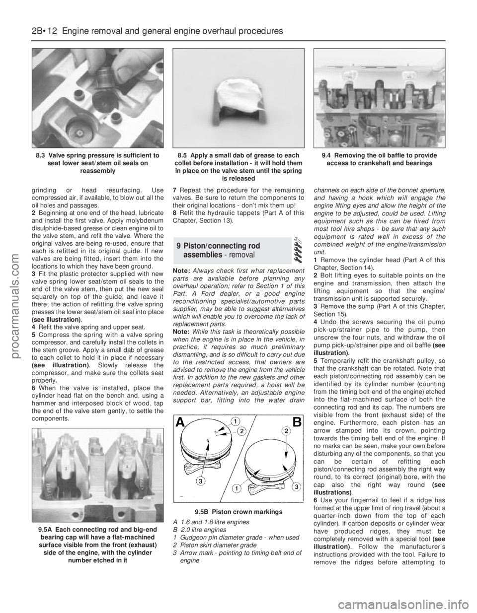
3Fit the plastic protector supplied with new
valve spring lower seat/stem oil seals to the
end of the valve stem, then put the new seal
squarely on top of the guide, and leave it
there; the action of refitting the valve spring
presses the lower seat/stem oil seal into place
(see illustration).
4Refit the valve spring and upper seat.
5Compress the spring with a valve spring
compressor, and carefully install the collets in
the stem groove. Apply a small dab of grease
to each collet to hold it in place if necessary
(see illustration). Slowly release the
compressor, and make sure the collets seat
properly.
6When the valve is installed, place the
cylinder head flat on the bench and, using a
hammer and interposed block of wood, tap
the end of the valve stem gently, to settle the
components.7Repeat the procedure for the remaining
valves. Be sure to return the components to
their original locations - don’t mix them up!
8Refit the hydraulic tappets (Part A of this
Chapter, Section 13).
Note:Always check first what replacement
parts are available before planning any
overhaul operation; refer to Section 1 of this
Part. A Ford dealer, or a good engine
reconditioning specialist/automotive parts
supplier, may be able to suggest alternatives
which will enable you to overcome the lack of
replacement parts.
Note:While this task is theoretically possible
when the engine is in place in the vehicle, in
practice, it requires so much preliminary
dismantling, and is so difficult to carry out due
to the restricted access, that owners are
advised to remove the engine from the vehicle
first. In addition to the new gaskets and other
replacement parts required, a hoist will be
needed. Alternatively, an adjustable engine
support bar, fitting into the water drainchannels on each side of the bonnet aperture,
and having a hook which will engage the
engine lifting eyes and allow the height of the
engine to be adjusted, could be used. Lifting
equipment such as this can be hired from
most tool hire shops - be sure that any such
equipment is rated well in excess of the
combined weight of the engine/transmission
unit.
1Remove the cylinder head (Part A of this
Chapter, Section 14).
2Bolt lifting eyes to suitable points on the
engine and transmission, then attach the
lifting equipment so that the engine/
transmission unit is supported securely.
3Remove the sump (Part A of this Chapter,
Section 15).
4Undo the screws securing the oil pump
pick-up/strainer pipe to the pump, then
unscrew the four nuts, and withdraw the oil
pump pick-up/strainer pipe and oil baffle (see
illustration).
5Temporarily refit the crankshaft pulley, so
that the crankshaft can be rotated. Note that
each piston/connecting rod assembly can be
identified by its cylinder number (counting
from the timing belt end of the engine) etched
into the flat-machined surface of both the
connecting rod and its cap. The numbers are
visible from the front (exhaust side) of the
engine. Furthermore, each piston has an
arrow stamped into its crown, pointing
towards the timing belt end of the engine. If
no marks can be seen, make your own before
disturbing any of the components, so that you
can be certain of refitting each
piston/connecting rod assembly the right way
round, to its correct (original) bore, with the
cap also the right way round (see
illustrations).
6Use your fingernail to feel if a ridge has
formed at the upper limit of ring travel (about a
quarter-inch down from the top of each
cylinder). If carbon deposits or cylinder wear
have produced ridges, they must be
completely removed with a special tool (see
illustration). Follow the manufacturer’s
instructions provided with the tool. Failure to
remove the ridges before attempting to
9 Piston/connecting rod
assemblies- removal
2B•12 Engine removal and general engine overhaul procedures
8.3 Valve spring pressure is sufficient to
seat lower seat/stem oil seals on
reassembly8.5 Apply a small dab of grease to each
collet before installation - it will hold them
in place on the valve stem until the spring
is released9.4 Removing the oil baffle to provide
access to crankshaft and bearings
9.5A Each connecting rod and big-end
bearing cap will have a flat-machined
surface visible from the front (exhaust)
side of the engine, with the cylinder
number etched in it
9.5B Piston crown markings
A 1.6 and 1.8 litre engines
B 2.0 litre engines
1 Gudgeon pin diameter grade - when used
2 Piston skirt diameter grade
3 Arrow mark - pointing to timing belt end of
engine
procarmanuals.com
Page 82 of 279
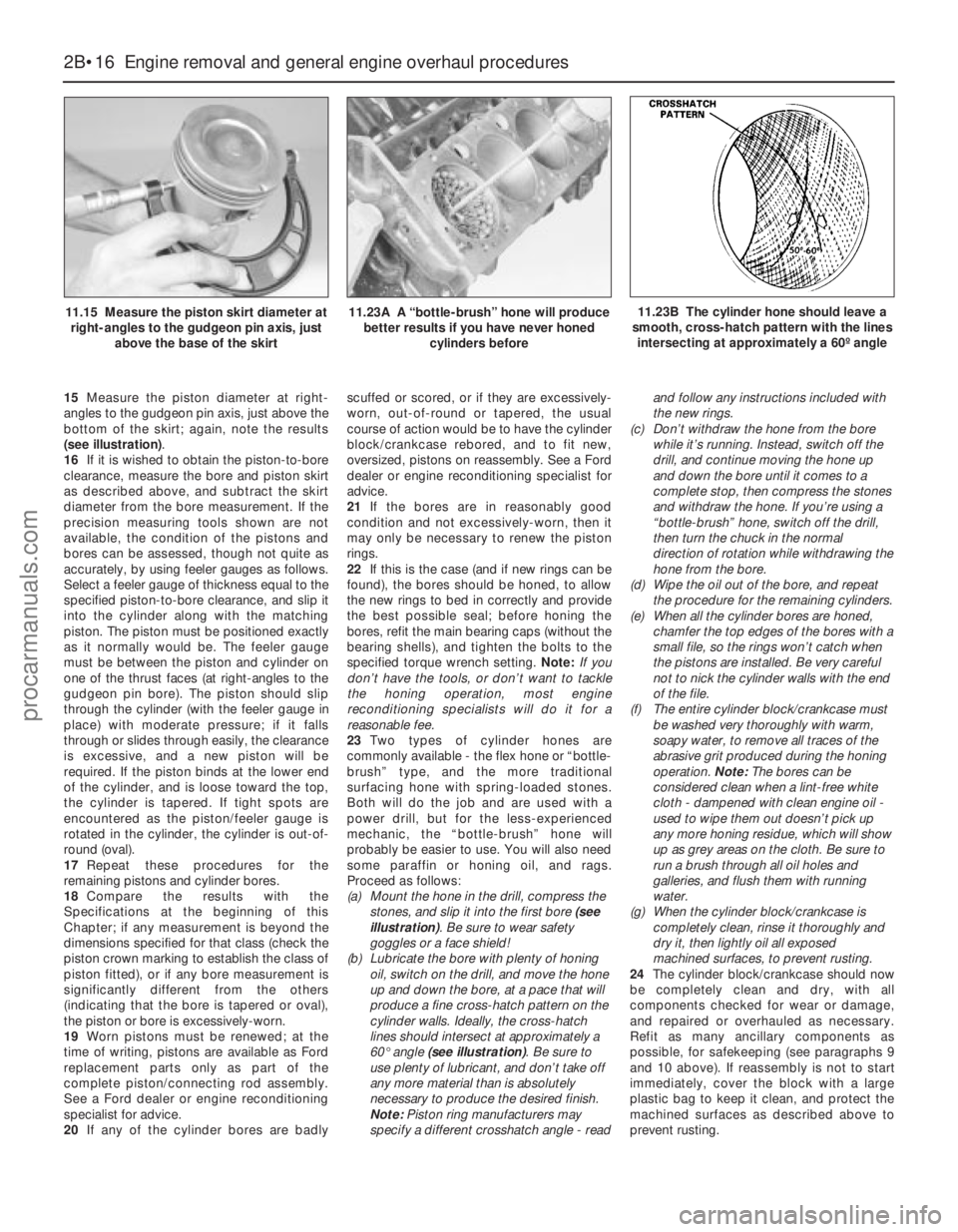
15Measure the piston diameter at right-
angles to the gudgeon pin axis, just above the
bottom of the skirt; again, note the results
(see illustration).
16If it is wished to obtain the piston-to-bore
clearance, measure the bore and piston skirt
as described above, and subtract the skirt
diameter from the bore measurement. If the
precision measuring tools shown are not
available, the condition of the pistons and
bores can be assessed, though not quite as
accurately, by using feeler gauges as follows.
Select a feeler gauge of thickness equal to the
specified piston-to-bore clearance, and slip it
into the cylinder along with the matching
piston. The piston must be positioned exactly
as it normally would be. The feeler gauge
must be between the piston and cylinder on
one of the thrust faces (at right-angles to the
gudgeon pin bore). The piston should slip
through the cylinder (with the feeler gauge in
place) with moderate pressure; if it falls
through or slides through easily, the clearance
is excessive, and a new piston will be
required. If the piston binds at the lower end
of the cylinder, and is loose toward the top,
the cylinder is tapered. If tight spots are
encountered as the piston/feeler gauge is
rotated in the cylinder, the cylinder is out-of-
round (oval).
17Repeat these procedures for the
remaining pistons and cylinder bores.
18Compare the results with the
Specifications at the beginning of this
Chapter; if any measurement is beyond the
dimensions specified for that class (check the
piston crown marking to establish the class of
piston fitted), or if any bore measurement is
significantly different from the others
(indicating that the bore is tapered or oval),
the piston or bore is excessively-worn.
19Worn pistons must be renewed; at the
time of writing, pistons are available as Ford
replacement parts only as part of the
complete piston/connecting rod assembly.
See a Ford dealer or engine reconditioning
specialist for advice.
20If any of the cylinder bores are badlyscuffed or scored, or if they are excessively-
worn, out-of-round or tapered, the usual
course of action would be to have the cylinder
block/crankcase rebored, and to fit new,
oversized, pistons on reassembly. See a Ford
dealer or engine reconditioning specialist for
advice.
21If the bores are in reasonably good
condition and not excessively-worn, then it
may only be necessary to renew the piston
rings.
22If this is the case (and if new rings can be
found), the bores should be honed, to allow
the new rings to bed in correctly and provide
the best possible seal; before honing the
bores, refit the main bearing caps (without the
bearing shells), and tighten the bolts to the
specified torque wrench setting. Note:If you
don’t have the tools, or don’t want to tackle
the honing operation, most engine
reconditioning specialists will do it for a
reasonable fee.
23Two types of cylinder hones are
commonly available - the flex hone or “bottle-
brush” type, and the more traditional
surfacing hone with spring-loaded stones.
Both will do the job and are used with a
power drill, but for the less-experienced
mechanic, the “bottle-brush” hone will
probably be easier to use. You will also need
some paraffin or honing oil, and rags.
Proceed as follows:
(a) Mount the hone in the drill, compress the
stones, and slip it into the first bore (see
illustration). Be sure to wear safety
goggles or a face shield!
(b) Lubricate the bore with plenty of honing
oil, switch on the drill, and move the hone
up and down the bore, at a pace that will
produce a fine cross-hatch pattern on the
cylinder walls. Ideally, the cross-hatch
lines should intersect at approximately a
60° angle (see illustration). Be sure to
use plenty of lubricant, and don’t take off
any more material than is absolutely
necessary to produce the desired finish.
Note:Piston ring manufacturers may
specify a different crosshatch angle - readand follow any instructions included with
the new rings.
(c) Don’t withdraw the hone from the bore
while it’s running. Instead, switch off the
drill, and continue moving the hone up
and down the bore until it comes to a
complete stop, then compress the stones
and withdraw the hone. If you’re using a
“bottle-brush” hone, switch off the drill,
then turn the chuck in the normal
direction of rotation while withdrawing the
hone from the bore.
(d) Wipe the oil out of the bore, and repeat
the procedure for the remaining cylinders.
(e) When all the cylinder bores are honed,
chamfer the top edges of the bores with a
small file, so the rings won’t catch when
the pistons are installed. Be very careful
not to nick the cylinder walls with the end
of the file.
(f) The entire cylinder block/crankcase must
be washed very thoroughly with warm,
soapy water, to remove all traces of the
abrasive grit produced during the honing
operation. Note:The bores can be
considered clean when a lint-free white
cloth - dampened with clean engine oil -
used to wipe them out doesn’t pick up
any more honing residue, which will show
up as grey areas on the cloth. Be sure to
run a brush through all oil holes and
galleries, and flush them with running
water.
(g) When the cylinder block/crankcase is
completely clean, rinse it thoroughly and
dry it, then lightly oil all exposed
machined surfaces, to prevent rusting.
24The cylinder block/crankcase should now
be completely clean and dry, with all
components checked for wear or damage,
and repaired or overhauled as necessary.
Refit as many ancillary components as
possible, for safekeeping (see paragraphs 9
and 10 above). If reassembly is not to start
immediately, cover the block with a large
plastic bag to keep it clean, and protect the
machined surfaces as described above to
prevent rusting.
2B•16 Engine removal and general engine overhaul procedures
11.15 Measure the piston skirt diameter at
right-angles to the gudgeon pin axis, just
above the base of the skirt11.23A A “bottle-brush” hone will produce
better results if you have never honed
cylinders before11.23B The cylinder hone should leave a
smooth, cross-hatch pattern with the lines
intersecting at approximately a 60º angle
procarmanuals.com