1993 FORD MONDEO low oil pressure
[x] Cancel search: low oil pressurePage 140 of 279
back again, as an assistant depresses the
accelerator pedal. If the valve shows any sign
of stiffness, sticking or otherwise-inhibited
movement (and the accelerator cable is
known from the previous check to be in good
condition), spray the throttle linkage with
penetrating lubricant, allow time for it to work,
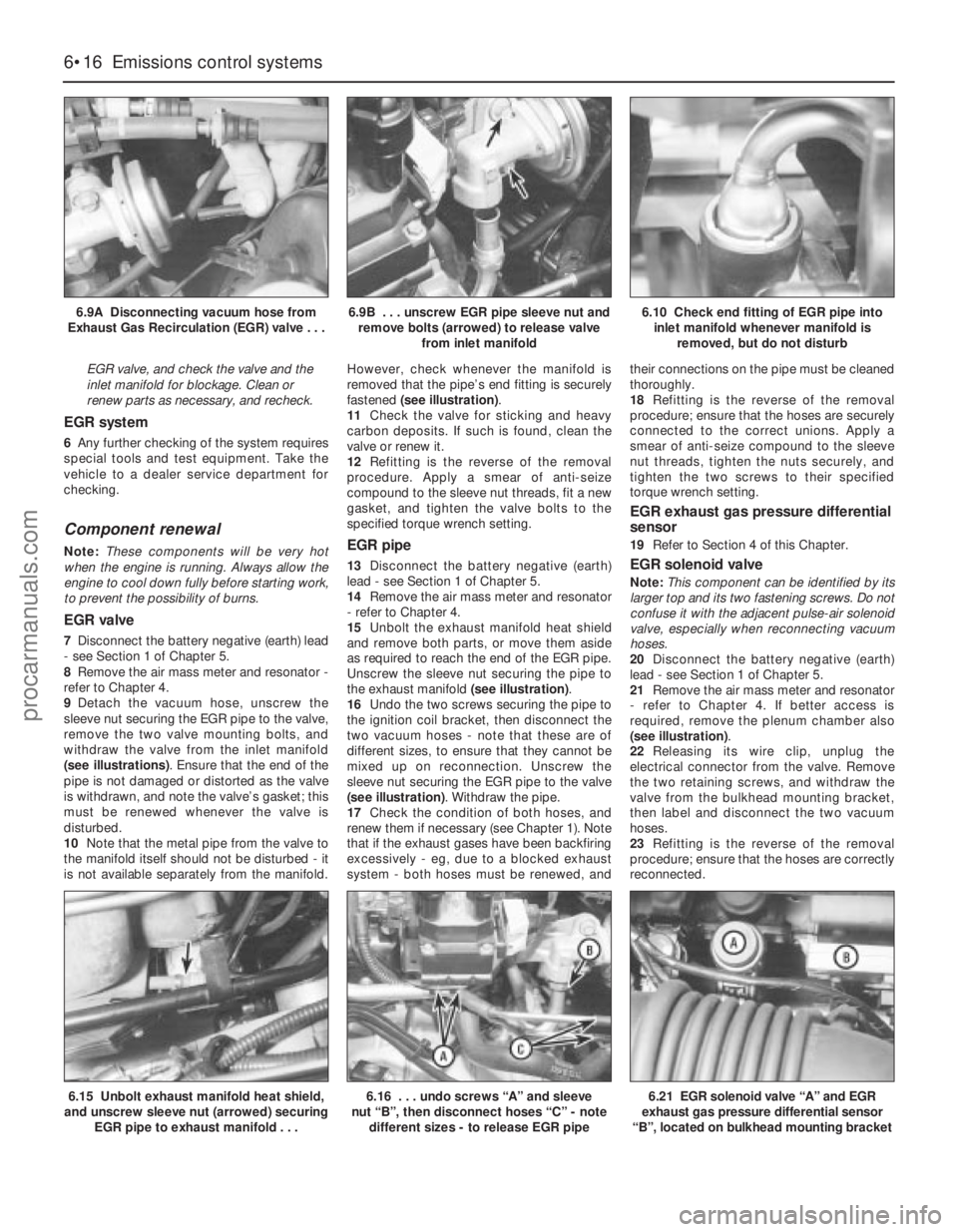
and repeat the check; if no improvement is
obtained, the complete throttle housing must
be renewed (Chapter 4).
15Unclip the air cleaner cover, and check
that the air filter element and the crankcase
ventilation system filter are not clogged or
soaked. (A clogged air filter will obstruct the
intake air flow, causing a noticeable effect on
engine performance; a clogged crankcase
ventilation system filter will inhibit crankcase
“breathing”). Renew or clean the filter(s) as
appropriate; refer to the relevant Sections of
Chapter 1 for further information, if required.
Before refitting the air cleaner cover, check
that the air intake (located under the front left-
hand wing, opening behind the direction
indicator/headlight assembly) is clear. It
should be possible to blow through the intake,
or to probe it (carefully) as far as the rear of
the direction indicator light.
16Start the engine and allow it to idle.
Note:Working in the engine compartment
while the engine is running requires great care
if the risk of personal injury is to be avoided;
among the dangers are burns from contact
with hot components, or contact with moving
components such as the radiator cooling fan
or the auxiliary drivebelt. Refer to “Safety
first!” at the front of this manual before
starting, and ensure that your hands, and long
hair or loose clothing, are kept well clear of hot
or moving components at all times.
17Working from the air intake junction at the
inner wing panel, via the air cleaner assembly
and air mass meter, to the resonator, plenum
chamber, throttle housing and inlet manifold
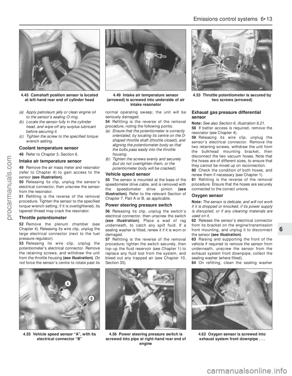
(and including the various vacuum hoses and
pipes connected to these), check for air leaks.
Usually, these will be revealed by sucking or
hissing noises, but minor leaks may be traced
by spraying a solution of soapy water on to
the suspect joint; if a leak exists, it will be
shown by the change in engine note and the
accompanying air bubbles (or sucking-in of
the liquid, depending on the pressure
difference at that point). If a leak is found at
any point, tighten the fastening clamp and/or
renew the faulty components, as applicable.
18Similarly, work from the cylinder head, via
the manifold (and not forgetting the related
EGR and pulse-air system components) to the
tailpipe, to check that the exhaust system is
free from leaks. The simplest way of doing
this, if the vehicle can be raised and
supported safely and with complete security
while the check is made, is to temporarily
block the tailpipe while listening for the sound
of escaping exhaust gases; any leak should
be evident. If a leak is found at any point,
tighten the fastening clamp bolts and/or nuts,
renew the gasket, and/or renew the faultysection of the system, as necessary, to seal
the leak.
19It is possible to make a further check of
the electrical connections by wiggling each
electrical connector of the system in turn as
the engine is idling; a faulty connector will be
immediately evident from the engine’s
response as contact is broken and remade. A
faulty connector should be renewed to ensure
the future reliability of the system; note that
this may mean the renewal of that entire
section of the loom - see your local Ford
dealer for details.
20Switch off the engine. If the fault is not yet
identified, the next step is to check the
ignition voltages, using an engine analyser
with an oscilloscope - without such
equipment, the only tests possible are to
remove and check each spark plug in turn, to
check the spark plug (HT) lead connections
and resistances, and to check the
connections and resistances of the ignition
coil. Refer to the relevant Sections of
Chapters 1 and 5.
21The final step in these preliminary checks
would be to use an exhaust gas analyser to
measure the CO level at the exhaust tailpipe.This check cannot be made without special
test equipment - see your local Ford dealer for
details.
Fault code read-out
22As noted in the general comments at the
beginning of this Section, the preliminary
checks outlined above should eliminate the
majority of faults from the engine
management system. If the fault is not yet
identified, the next step is to connect a fault
code reader to the ECU, so that its self-
diagnosis facility can be used to identify the
faulty part of the system; further tests can
then be made to identify the exact cause of
the fault.
23In their basic form, fault code readers are
simply hand-held electronic devices, which
take data stored within an ECU’s memory and
display it when required as two- or three-digit
fault codes. The more sophisticated versions
now available can also control sensors and
actuators, to provide more effective testing;
some can store information, so that a road
test can be carried out, and any faults
encountered during the test can be displayed
afterwards.
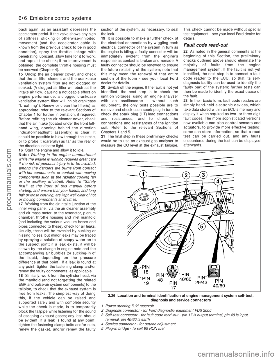
6•6 Emissions control systems
3.26 Location and terminal identification of engine management system self-test,
diagnosis and service connectors
1 Power steering fluid reservoir
2 Diagnosis connector - for Ford diagnostic equipment FDS 2000
3 Self-test connector - for fault code read-out - pin 17 is output terminal, pin 48 is input
terminal, pin 40/60 is earth
4 Service connector - for octane adjustment
5 Plug-in bridge - to suit 95 RON fuel
procarmanuals.com
Page 142 of 279
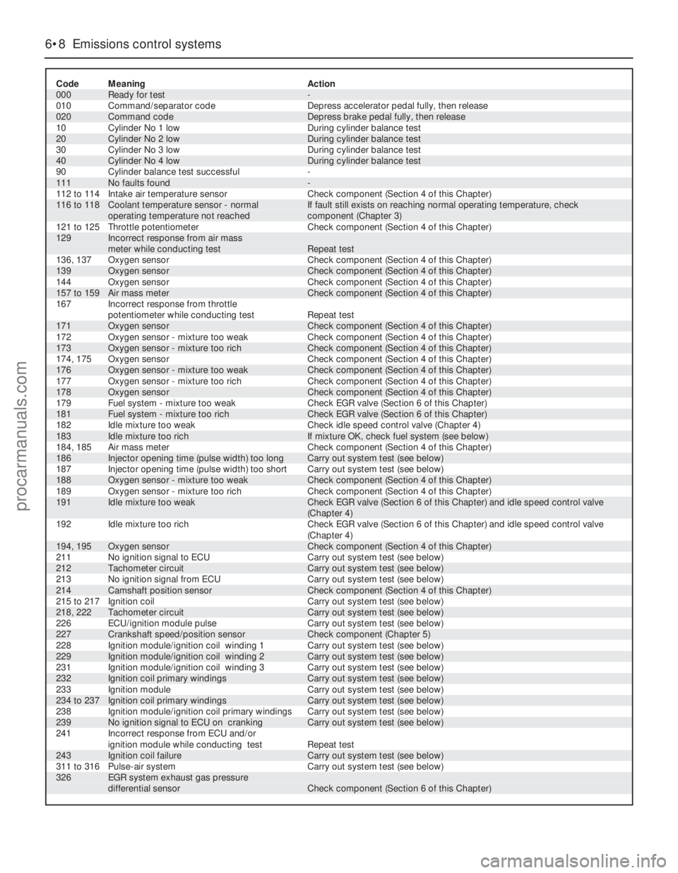
6•8 Emissions control systems
Code Meaning Action
000 Ready for test -
010 Command/separator code Depress accelerator pedal fully, then release
020 Command code Depress brake pedal fully, then release
10 Cylinder No 1 low During cylinder balance test
20 Cylinder No 2 low During cylinder balance test
30 Cylinder No 3 low During cylinder balance test
40 Cylinder No 4 low During cylinder balance test
90 Cylinder balance test successful -
111 No faults found -
112 to 114 Intake air temperature sensor Check component (Section 4 of this Chapter)116 to 118 Coolant temperature sensor - normal If fault still exists on reaching normal operating temperature, check
operating temperature not reached component (Chapter 3)
121 to 125 Throttle potentiometer Check component (Section 4 of this Chapter)129 Incorrect response from air mass
meter while conducting test Repeat test
136, 137 Oxygen sensor Check component (Section 4 of this Chapter)
139 Oxygen sensor Check component (Section 4 of this Chapter)
144 Oxygen sensor Check component (Section 4 of this Chapter)
157 to 159 Air mass meter Check component (Section 4 of this Chapter)
167 Incorrect response from throttle
potentiometer while conducting test Repeat test
171 Oxygen sensor Check component (Section 4 of this Chapter)
172 Oxygen sensor - mixture too weak Check component (Section 4 of this Chapter)
173 Oxygen sensor - mixture too rich Check component (Section 4 of this Chapter)
174, 175 Oxygen sensor Check component (Section 4 of this Chapter)
176 Oxygen sensor - mixture too weak Check component (Section 4 of this Chapter)
177 Oxygen sensor - mixture too rich Check component (Section 4 of this Chapter)
178 Oxygen sensor Check component (Section 4 of this Chapter)
179 Fuel system - mixture too weak Check EGR valve (Section 6 of this Chapter)
181 Fuel system - mixture too rich Check EGR valve (Section 6 of this Chapter)
182 Idle mixture too weak Check idle speed control valve (Chapter 4)
183 Idle mixture too rich If mixture OK, check fuel system (see below)
184, 185 Air mass meter Check component (Section 4 of this Chapter)
186 Injector opening time (pulse width) too long Carry out system test (see below)
187 Injector opening time (pulse width) too short Carry out system test (see below)
188 Oxygen sensor - mixture too weak Check component (Section 4 of this Chapter)
189 Oxygen sensor - mixture too rich Check component (Section 4 of this Chapter)191 Idle mixture too weak Check EGR valve (Section 6 of this Chapter) and idle speed control valve
(Chapter 4)
192 Idle mixture too rich Check EGR valve (Section 6 of this Chapter) and idle speed control valve
(Chapter 4)
194, 195 Oxygen sensor Check component (Section 4 of this Chapter)
211 No ignition signal to ECU Carry out system test (see below)
212 Tachometer circuit Carry out system test (see below)
213 No ignition signal from ECU Carry out system test (see below)
214 Camshaft position sensor Check component (Section 4 of this Chapter)
215 to 217 Ignition coil Carry out system test (see below)
218, 222 Tachometer circuit Carry out system test (see below)
226 ECU/ignition module pulse Carry out system test (see below)
227 Crankshaft speed/position sensor Check component (Chapter 5)
228 Ignition module/ignition coil winding 1 Carry out system test (see below)
229 Ignition module/ignition coil winding 2 Carry out system test (see below)
231 Ignition module/ignition coil winding 3 Carry out system test (see below)
232 Ignition coil primary windings Carry out system test (see below)
233 Ignition module Carry out system test (see below)
234 to 237 Ignition coil primary windings Carry out system test (see below)
238 Ignition module/ignition coil primary windings Carry out system test (see below)
239 No ignition signal to ECU on cranking Carry out system test (see below)
241 Incorrect response from ECU and/or
ignition module while conducting test Repeat test
243 Ignition coil failure Carry out system test (see below)
311 to 316 Pulse-air system Carry out system test (see below)326 EGR system exhaust gas pressure
differential sensor Check component (Section 6 of this Chapter)
procarmanuals.com
Page 144 of 279
Ignition timing and base idle
speed check
Note:The following procedure is a check only,
essentially of the ECU. Both the ignition timing
and the base idle speed are controlled by the
ECU. The ignition timing is not adjustable at
all; the base idle speed is set in production,
and should not be altered.
38If the fault code read-out (with any checks
resulting from it) has not eliminated the fault,
the next step is to check the ECU’s control of
the ignition timing and the base idle speed.
This task requires the use of a Ford STAR
tester (a proprietary fault code reader can be
used only if it is capable of inducing the ECU
to enter its “Service Adjustment Programme”),
coupled with an accurate tachometer and a
good-quality timing light. Without this
equipment, the task is not possible; the
vehicle must be taken to a Ford dealer for
attention.
39To make the check, apply the handbrake,
switch off the air conditioning (where fitted)
and any other electrical loads (lights, heated
rear window, etc), then select neutral (manual
transmission) or the “P” position (automatic
transmission). Start the engine, and warm it
up to normal operating temperature. The
radiator electric cooling fan must be running
continuously while the check is made; this
should be activated by the ECU, when
prompted by the tester. Switch off the engine,
and connect the test equipment as directed
by the manufacturer - refer to paragraph 26
above for details of STAR tester connection.
40Raise and support the front of the vehicle
securely, and remove the auxiliary drivebelt
cover (see Chapter 1). Emphasise the two
pairs of notches in the inner and outer rims of
the crankshaft pulley, using white paint. Note
that an ignition timing reference mark is not
provided on the pulley - in the normal
direction of crankshaft rotation (clockwise,
seen from the right-hand side of the vehicle)
the first pair of notches are irrelevant to the
vehicles covered in this manual, while the
second pair indicate Top Dead Centre (TDC)
when aligned with the rear edge of the raised
mark on the sump; when checking the ignition
timing, therefore, the (rear edge of the) sumpmark should appear just before the TDC
notches (see Part A of Chapter 2, Section 4,
for further information if required).
41Start the engine and allow it to idle. Work
through the engine-running test procedure
until the ECU enters its “Service Adjustment
Programme” - see paragraph 35 above.
42Use the timing light to check that the
timing marks appear approximately as
outlined above at idle speed. Do not spend
too much time on this check; if the timing
appears to be incorrect, the system may have
a fault, and a full system test must be carried
out (see below) to establish its cause.
43Using the tachometer, check that the
base idle speed is as given in the
Specifications Section of Chapter 4.
44If the recorded speed differs significantly
from the specified value, check for air leaks,
as described in the preliminary checks
(paragraphs 15 to 18 above), or any other
faults which might cause the discrepancy.
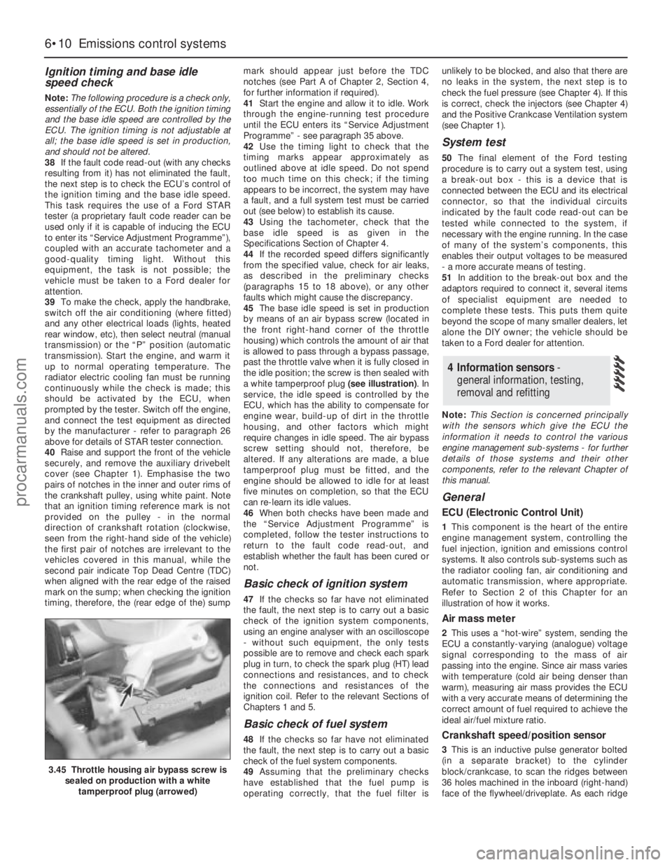
45The base idle speed is set in production
by means of an air bypass screw (located in
the front right-hand corner of the throttle
housing) which controls the amount of air that
is allowed to pass through a bypass passage,
past the throttle valve when it is fully closed in
the idle position; the screw is then sealed with
a white tamperproof plug (see illustration). In
service, the idle speed is controlled by the
ECU, which has the ability to compensate for
engine wear, build-up of dirt in the throttle
housing, and other factors which might
require changes in idle speed. The air bypass
screw setting should not, therefore, be
altered. If any alterations are made, a blue
tamperproof plug must be fitted, and the
engine should be allowed to idle for at least
five minutes on completion, so that the ECU
can re-learn its idle values.
46When both checks have been made and
the “Service Adjustment Programme” is
completed, follow the tester instructions to
return to the fault code read-out, and
establish whether the fault has been cured or
not.
Basic check of ignition system
47If the checks so far have not eliminated
the fault, the next step is to carry out a basic
check of the ignition system components,
using an engine analyser with an oscilloscope
- without such equipment, the only tests
possible are to remove and check each spark
plug in turn, to check the spark plug (HT) lead
connections and resistances, and to check
the connections and resistances of the
ignition coil. Refer to the relevant Sections of
Chapters 1 and 5.
Basic check of fuel system
48If the checks so far have not eliminated
the fault, the next step is to carry out a basic
check of the fuel system components.
49Assuming that the preliminary checks
have established that the fuel pump is
operating correctly, that the fuel filter isunlikely to be blocked, and also that there are
no leaks in the system, the next step is to
check the fuel pressure (see Chapter 4). If this
is correct, check the injectors (see Chapter 4)
and the Positive Crankcase Ventilation system
(see Chapter 1).
System test
50The final element of the Ford testing
procedure is to carry out a system test, using
a break-out box - this is a device that is
connected between the ECU and its electrical
connector, so that the individual circuits
indicated by the fault code read-out can be
tested while connected to the system, if
necessary with the engine running. In the case
of many of the system’s components, this
enables their output voltages to be measured
- a more accurate means of testing.
51In addition to the break-out box and the
adaptors required to connect it, several items
of specialist equipment are needed to
complete these tests. This puts them quite
beyond the scope of many smaller dealers, let
alone the DIY owner; the vehicle should be
taken to a Ford dealer for attention.
Note:This Section is concerned principally
with the sensors which give the ECU the
information it needs to control the various
engine management sub-systems - for further
details of those systems and their other
components, refer to the relevant Chapter of
this manual.
General
ECU (Electronic Control Unit)
1This component is the heart of the entire
engine management system, controlling the
fuel injection, ignition and emissions control
systems. It also controls sub-systems such as
the radiator cooling fan, air conditioning and
automatic transmission, where appropriate.
Refer to Section 2 of this Chapter for an
illustration of how it works.
Air mass meter
2This uses a “hot-wire” system, sending the
ECU a constantly-varying (analogue) voltage
signal corresponding to the mass of air
passing into the engine. Since air mass varies
with temperature (cold air being denser than
warm), measuring air mass provides the ECU
with a very accurate means of determining the
correct amount of fuel required to achieve the
ideal air/fuel mixture ratio.
Crankshaft speed/position sensor
3This is an inductive pulse generator bolted
(in a separate bracket) to the cylinder
block/crankcase, to scan the ridges between
36 holes machined in the inboard (right-hand)
face of the flywheel/driveplate. As each ridge
4 Information sensors -
general information, testing,
removal and refitting
6•10 Emissions control systems
3.45 Throttle housing air bypass screw is
sealed on production with a white
tamperproof plug (arrowed)
procarmanuals.com
Page 146 of 279
Vehicle speed sensor
29Testing of this component is beyond the
scope of the DIY mechanic, and should be left
to a Ford dealer.
Power steering pressure switch
30Unplug the electrical connector from the
sensor.
31Using an ohmmeter, measure the
resistance between the switch terminals. With
the engine switched off, or idling with the
roadwheels in the straight-ahead position,
little or no resistance should be measured.
With the engine running and the steering on
full-lock, the pressure increase in the system
should open the switch contacts, so that
infinite resistance is now measured.
32If the results obtained show the switch to
be faulty, renew it.
Exhaust gas pressure differential
sensor
33Testing of this component is beyond the
scope of the DIY mechanic, and should be left
to a Ford dealer.
Oxygen sensor
34Testing of this component can be done
only by attaching special diagnostic
equipment to the sensor wiring, and checking
that the voltage varies from low to high values
when the engine is running; do notattempt to
“test” any part of the system with anything
other than the correct test equipment. This is
beyond the scope of the DIY mechanic, and
should be left to a Ford dealer.
Removal and refitting
General
35Before disconnecting any of these
components, always disconnect the power by
uncoupling the battery terminals, negative
(earth) lead first - see Section 1 of Chapter 5.
ECU (Electronic Control Unit)
Note:The ECU is fragile. Take care not to
drop it or subject it to any other kind of
impact, and do not subject it to extremes of
temperature, or allow it to get wet.
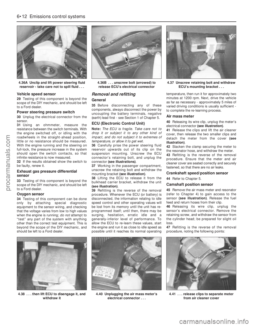
36Carefully prise the power steering fluid
reservoir upwards out of its clip on the
suspension mounting. Unscrew the ECU
connector’s retaining bolt, and unplug the
connector (see illustrations).
37Working in the passenger compartment,
unscrew the retaining bolt and withdraw the
mounting bracket (see illustration).
38Lifting the ECU to release it from the
bulkhead carrier bracket, withdraw the unit
(see illustration).
39Refitting is the reverse of the removal
procedure. Whenever the ECU (or battery) is
disconnected, the information relating to idle
speed control and other operating values will
be lost from its memory until the unit has re-
programmed itself; until then, there may be
surging, hesitation, erratic idle and a
generally-inferior level of performance. To
allow the ECU to re-learn these values, start
the engine and run it as close to idle speed as
possible until it reaches its normal operatingtemperature, then run it for approximately two
minutes at 1200 rpm. Next, drive the vehicle
as far as necessary - approximately 5 miles of
varied driving conditions is usually sufficient -
to complete the re-learning process.
Air mass meter
40Releasing its wire clip, unplug the meter’s
electrical connector (see illustration).
41Release the clips and lift the air cleaner
cover, then release the two smaller clips and
detach the meter from the cover (see
illustration).
42Slacken the clamp securing the meter to
the resonator hose, and withdraw the meter.
43Refitting is the reverse of the removal
procedure. Ensure that the meter and air
cleaner cover are seated correctly and securely
fastened, so that there are no air leaks.
Crankshaft speed/position sensor
44Refer to Chapter 5.
Camshaft position sensor
45Remove the air mass meter and resonator
(refer to Chapter 4) to gain access to the
sensor (see illustration). Release the fuel
feed and return hoses from their clip.
46Releasing its wire clip, unplug the
sensor’s electrical connector. Remove the
retaining screw, and withdraw the sensor from
the cylinder head; be prepared for slight oil
loss.
47Refitting is the reverse of the removal
procedure, noting the following points:
6•12 Emissions control systems
4.36A Unclip and lift power steering fluid
reservoir - take care not to spill fluid . . .4.36B . . . unscrew bolt (arrowed) to
release ECU’s electrical connector4.37 Unscrew retaining bolt and withdraw
ECU’s mounting bracket . . .
4.40 Unplugging the air mass meter’s
electrical connector . . .4.38 . . . then lift ECU to disengage it, and
withdraw it4.41 . . . release clips to separate meter
from air cleaner cover
procarmanuals.com
Page 147 of 279
(a) Apply petroleum jelly or clean engine oil
to the sensor’s sealing O-ring.
(b) Locate the sensor fully in the cylinder
head, and wipe off any surplus lubricant
before securing it.
(c) Tighten the screw to the specified torque
wrench setting.
Coolant temperature sensor
48Refer to Chapter 3, Section 6.
Intake air temperature sensor
49Remove the air mass meter and resonator
(refer to Chapter 4) to gain access to the
sensor (see illustration).
50Releasing its clip, unplug the sensor’s
electrical connector, then unscrew the sensor
from the resonator.
51Refitting is the reverse of the removal
procedure. Tighten the sensor to the specified
torque wrench setting; if it is overtightened, its
tapered thread may crack the resonator.
Throttle potentiometer
52Remove the plenum chamber (see
Chapter 4). Releasing its wire clip, unplug the
large electrical connector (next to the fuel
pressure regulator).
53Releasing its wire clip, unplug the
potentiometer’s electrical connector. Remove
the retaining screws, and withdraw the unit
from the throttle housing (see illustration). Do
notforce the sensor’s centre to rotate past itsnormal operating sweep; the unit will be
seriously damaged.
54Refitting is the reverse of the removal
procedure, noting the following points:
(a) Ensure that the potentiometer is correctly
orientated, by locating its centre on the D-
shaped throttle shaft (throttle closed), and
aligning the potentiometer body so that
the bolts pass easily into the throttle
housing.
(b) Tighten the screws evenly and securely
(but do not overtighten them, or the
potentiometer body will be cracked).
Vehicle speed sensor
55The sensor is mounted at the base of the
speedometer drive cable, and is removed with
the speedometer drive pinion (see
illustration). Refer to the relevant Section of
Chapter 7, Part A or B, as applicable.
Power steering pressure switch
56Releasing its clip, unplug the switch’s
electrical connector, then unscrew the switch
(see illustration). Place a wad of rag
underneath, to catch any spilt fluid. If a
sealing washer is fitted, renew it if it is worn or
damaged.
57Refitting is the reverse of the removal
procedure; tighten the switch securely, then
top-up the fluid reservoir (see Chapter 1) to
replace any fluid lost from the system, and
bleed out any trapped air (see Chapter 10,
Section 33).
Exhaust gas pressure differential
sensor
Note:See also Section 6, illustration 6.21.
58If better access is required, remove the
resonator (see Chapter 4).
59Releasing its wire clip, unplug the
sensor’s electrical connector. Remove the
two retaining screws, withdraw the unit from
the bulkhead mounting bracket, then
disconnect the two vacuum hoses. Note that
the hoses are of different sizes, to ensure that
they cannot be mixed up on reconnection.
60Check the condition of both hoses, and
renew them if necessary (see Chapter 1).
61Refitting is the reverse of the removal
procedure. Ensure that the hoses are securely
connected to the correct unions.
Oxygen sensor
Note:The sensor is delicate, and will not work
if it is dropped or knocked, if its power supply
is disrupted, or if any cleaning materials are
used on it.
62Release the sensor’s electrical connector
from its bracket on the engine/transmission
front mounting, and unplug it to disconnect
the sensor (see illustration).
63Raising and supporting the front of the
vehicle if required to remove the sensor from
underneath, unscrew the sensor from the
exhaust system front downpipe; collect the
sealing washer (where fitted).
64On refitting, clean the sealing washer
Emissions control systems 6•13
6
4.56 Power steering pressure switch is
screwed into pipe at right-hand rear end of
engine4.62 Oxygen sensor is screwed into
exhaust system front downpipe . . .
4.49 Intake air temperature sensor
(arrowed) is screwed into underside of air
intake resonator4.53 Throttle potentiometer is secured by
two screws (arrowed)
4.55 Vehicle speed sensor “A”, with its
electrical connector “B”
4.45 Camshaft position sensor is located
at left-hand rear end of cylinder head
procarmanuals.com
Page 150 of 279
EGR valve, and check the valve and the
inlet manifold for blockage. Clean or
renew parts as necessary, and recheck.
EGR system
6Any further checking of the system requires
special tools and test equipment. Take the
vehicle to a dealer service department for
checking.
Component renewal
Note:These components will be very hot
when the engine is running. Always allow the
engine to cool down fully before starting work,
to prevent the possibility of burns.
EGR valve
7Disconnect the battery negative (earth) lead
- see Section 1 of Chapter 5.
8Remove the air mass meter and resonator -
refer to Chapter 4.
9Detach the vacuum hose, unscrew the
sleeve nut securing the EGR pipe to the valve,
remove the two valve mounting bolts, and
withdraw the valve from the inlet manifold
(see illustrations). Ensure that the end of the
pipe is not damaged or distorted as the valve
is withdrawn, and note the valve’s gasket; this
must be renewed whenever the valve is
disturbed.
10Note that the metal pipe from the valve to
the manifold itself should not be disturbed - it
is not available separately from the manifold.However, check whenever the manifold is
removed that the pipe’s end fitting is securely
fastened (see illustration).
11Check the valve for sticking and heavy
carbon deposits. If such is found, clean the
valve or renew it.
12Refitting is the reverse of the removal
procedure. Apply a smear of anti-seize
compound to the sleeve nut threads, fit a new
gasket, and tighten the valve bolts to the
specified torque wrench setting.
EGR pipe
13Disconnect the battery negative (earth)
lead - see Section 1 of Chapter 5.
14Remove the air mass meter and resonator
- refer to Chapter 4.
15Unbolt the exhaust manifold heat shield
and remove both parts, or move them aside
as required to reach the end of the EGR pipe.
Unscrew the sleeve nut securing the pipe to
the exhaust manifold (see illustration).
16Undo the two screws securing the pipe to
the ignition coil bracket, then disconnect the
two vacuum hoses - note that these are of
different sizes, to ensure that they cannot be
mixed up on reconnection. Unscrew the
sleeve nut securing the EGR pipe to the valve
(see illustration). Withdraw the pipe.
17Check the condition of both hoses, and
renew them if necessary (see Chapter 1). Note
that if the exhaust gases have been backfiring
excessively - eg, due to a blocked exhaust
system - both hoses must be renewed, andtheir connections on the pipe must be cleaned
thoroughly.
18Refitting is the reverse of the removal
procedure; ensure that the hoses are securely
connected to the correct unions. Apply a
smear of anti-seize compound to the sleeve
nut threads, tighten the nuts securely, and
tighten the two screws to their specified
torque wrench setting.
EGR exhaust gas pressure differential
sensor
19Refer to Section 4 of this Chapter.
EGR solenoid valve
Note:This component can be identified by its
larger top and its two fastening screws. Do not
confuse it with the adjacent pulse-air solenoid
valve, especially when reconnecting vacuum
hoses.
20Disconnect the battery negative (earth)
lead - see Section 1 of Chapter 5.
21Remove the air mass meter and resonator
- refer to Chapter 4. If better access is
required, remove the plenum chamber also
(see illustration).
22Releasing its wire clip, unplug the
electrical connector from the valve. Remove
the two retaining screws, and withdraw the
valve from the bulkhead mounting bracket,
then label and disconnect the two vacuum
hoses.
23Refitting is the reverse of the removal
procedure; ensure that the hoses are correctly
reconnected.
6•16 Emissions control systems
6.9A Disconnecting vacuum hose from
Exhaust Gas Recirculation (EGR) valve . . .6.9B . . . unscrew EGR pipe sleeve nut and
remove bolts (arrowed) to release valve
from inlet manifold6.10 Check end fitting of EGR pipe into
inlet manifold whenever manifold is
removed, but do not disturb
6.15 Unbolt exhaust manifold heat shield,
and unscrew sleeve nut (arrowed) securing
EGR pipe to exhaust manifold . . .6.16 . . . undo screws “A” and sleeve
nut “B”, then disconnect hoses “C” - note
different sizes - to release EGR pipe6.21 EGR solenoid valve “A” and EGR
exhaust gas pressure differential sensor
“B”, located on bulkhead mounting bracket
procarmanuals.com
Page 155 of 279
Chapter 10 Suspension and steering systems
Front anti-roll bar and links - removal and refitting . . . . . . . . . . . . . . 6
Front hub and bearings - inspection and renewal . . . . . . . . . . . . . . 3
Front suspension lower arm - removal, overhaul and refitting . . . . . 7
Front suspension lower arm balljoint - renewal . . . . . . . . . . . . . . . . 8
Front suspension strut - overhaul . . . . . . . . . . . . . . . . . . . . . . . . . . . 5
Front suspension strut - removal and refitting . . . . . . . . . . . . . . . . . 4
General information . . . . . . . . . . . . . . . . . . . . . . . . . . . . . . . . . . . . . . 1
Power steering fluid level check . . . . . . . . . . . . . . . . . See Chapter 1
Power steering gear (all except left-hand-drive models
with ABS) - removal and refitting . . . . . . . . . . . . . . . . . . . . . . . . . . 30
Power steering gear (left-hand-drive models with ABS) -
removal and refitting . . . . . . . . . . . . . . . . . . . . . . . . . . . . . . . . . . . 31
Power steering gear rubber gaiters - renewal . . . . . . . . . . . . . . . . . . 32
Power steering hydraulic system - bleeding . . . . . . . . . . . . . . . . . . . 33
Power steering pump - removal and refitting . . . . . . . . . . . . . . . . . . 34
Rear anti-roll bar and links (Estate models) - removal and refitting . 20
Rear anti-roll bar and links (Saloon/Hatchback models) -
removal and refitting . . . . . . . . . . . . . . . . . . . . . . . . . . . . . . . . . . . 13
Rear coil spring (Estate models) - removal and refitting . . . . . . . . . . 21
Rear hub and bearings (Estate models) - inspection and renewal . . 17
Rear hub and bearings (Saloon/Hatchback models) -
inspection and renewal . . . . . . . . . . . . . . . . . . . . . . . . . . . . . . . . . 9
Rear shock absorber (Estate models) - removal, testing and refitting . 19
Rear suspension crossmember (Estate models) - removal
and refitting . . . . . . . . . . . . . . . . . . . . . . . . . . . . . . . . . . . . . . . . . . 26
Rear suspension crossmember (Saloon/Hatchback models) -
removal and refitting . . . . . . . . . . . . . . . . . . . . . . . . . . . . . . . . . . . 16Rear suspension front lower arm (Estate models) - removal
and refitting . . . . . . . . . . . . . . . . . . . . . . . . . . . . . . . . . . . . . . . . . . 23
Rear suspension knuckle (Estate models) - removal and refitting . . 18
Rear suspension knuckle (Saloon/Hatchback models) - removal
and refitting . . . . . . . . . . . . . . . . . . . . . . . . . . . . . . . . . . . . . . . . . . 10
Rear suspension lower arms (Saloon/Hatchback models) -
removal and refitting . . . . . . . . . . . . . . . . . . . . . . . . . . . . . . . . . . . 14
Rear suspension rear lower arm (Estate models) - removal
and refitting . . . . . . . . . . . . . . . . . . . . . . . . . . . . . . . . . . . . . . . . . . 22
Rear suspension strut (Saloon/Hatchback models) - overhaul . . . . . 12
Rear suspension strut (Saloon/Hatchback models) -
removal and refitting . . . . . . . . . . . . . . . . . . . . . . . . . . . . . . . . . . . 11
Rear suspension tie-bar (Estate models) - removal and refitting . . . 25
Rear suspension tie-bar (Saloon/Hatchback models) -
removal and refitting . . . . . . . . . . . . . . . . . . . . . . . . . . . . . . . . . . . 15
Rear suspension upper arm (Estate models) - removal
and refitting . . . . . . . . . . . . . . . . . . . . . . . . . . . . . . . . . . . . . . . . . . 24
Steering column - removal, inspection and refitting . . . . . . . . . . . . . 28
Steering column flexible coupling - removal and refitting . . . . . . . . . 29
Steering knuckle and hub assembly - removal and refitting . . . . . . . 2
Steering, suspension and wheel check . . . . . . . . . . . . See Chapter 1
Steering wheel - removal and refitting . . . . . . . . . . . . . . . . . . . . . . . 27
Track rod end - renewal . . . . . . . . . . . . . . . . . . . . . . . . . . . . . . . . . . 35
Tyre condition and tyre pressure checks . . . . . . . . . . . See Chapter 1
Wheel alignment and steering angles - general information . . . . . . . 36
Front wheel alignment
Toe setting:
Tolerance allowed before resetting required . . . . . . . . . . . . . . . . . . . . 0.5 mm to 3.5 mm toe-out (0°05’ to 0°35’ toe-out)
Adjustment setting (if required) . . . . . . . . . . . . . . . . . . . . . . . . . . . . . . 2.0 mm ± 1.0 mm toe-out (0°20’ ± 0°10’ toe-out)
Rear wheel alignment
Toe setting:
Tolerance allowed before resetting required:
Saloon/Hatchback . . . . . . . . . . . . . . . . . . . . . . . . . . . . . . . . . . . . . . 3.9 mm toe-in to 0.1 mm toe-out (0°38’ toe-in to 0°02’ toe-out)
Estate . . . . . . . . . . . . . . . . . . . . . . . . . . . . . . . . . . . . . . . . . . . . . . . . 2.7 mm toe-in to 1.3 mm toe-out (0°27’ toe-in to 0°13’ toe-out)
Adjustment setting (if required):
Saloon/Hatchback . . . . . . . . . . . . . . . . . . . . . . . . . . . . . . . . . . . . . . 1.9 mm ± 1.2 mm toe-in (0°18’ ± 0°12’ toe-in)
Estate . . . . . . . . . . . . . . . . . . . . . . . . . . . . . . . . . . . . . . . . . . . . . . . . 0.7 mm ± 1.2 mm toe-in (0°07’ ± 0°12’ toe-in)
Roadwheels and tyres
Wheel sizes:
Steel . . . . . . . . . . . . . . . . . . . . . . . . . . . . . . . . . . . . . . . . . . . . . . . . . . 14 x 5 1/2
Alloy . . . . . . . . . . . . . . . . . . . . . . . . . . . . . . . . . . . . . . . . . . . . . . . . . . . 14 x 5 1/2 or 15 x 6
Tyre sizes:
Wheel size 14 x 5 1/2 . . . . . . . . . . . . . . . . . . . . . . . . . . . . . . . . . . . . . 185/65/14 or 195/60VR/14
Wheel size 15 x 6 . . . . . . . . . . . . . . . . . . . . . . . . . . . . . . . . . . . . . . . . 205/55VR/15
Tyre pressures . . . . . . . . . . . . . . . . . . . . . . . . . . . . . . . . . . . . . . . . . . . . . See Chapter 1 Specifications
10•1
Easy,suitable for
novice with little
experienceFairly easy,suitable
for beginner with
some experienceFairly difficult,suitable
for competent DIY
mechanicDifficult,suitable for
experienced DIY
mechanicVery difficult,
suitable for expert DIY
or professional
Degrees of difficulty
Specifications Contents
10
procarmanuals.com
Page 260 of 279
Introduction
A selection of good tools is a fundamental
requirement for anyone contemplating the
maintenance and repair of a motor vehicle.
For the owner who does not possess any,
their purchase will prove a considerable
expense, offsetting some of the savings made
by doing-it-yourself. However, provided that
the tools purchased meet the relevant national
safety standards and are of good quality, they
will last for many years and prove an
extremely worthwhile investment.
To help the average owner to decide which
tools are needed to carry out the various tasks
detailed in this manual, we have compiled
three lists of tools under the following
headings: Maintenance and minor repair,
Repair and overhaul, and Special. Newcomers
to practical mechanics should start off with
the Maintenance and minor repairtool kit, and
confine themselves to the simpler jobs around
the vehicle. Then, as confidence and
experience grow, more difficult tasks can be
undertaken, with extra tools being purchased
as, and when, they are needed. In this way, a
Maintenance and minor repairtool kit can be
built up into a Repair and overhaultool kit over
a considerable period of time, without any
major cash outlays. The experienced do-it-
yourselfer will have a tool kit good enough for
most repair and overhaul procedures, and will
add tools from the Specialcategory when it is
felt that the expense is justified by the amount
of use to which these tools will be put.
Maintenance and minor repair
tool kit
The tools given in this list should be
considered as a minimum requirement if
routine maintenance, servicing and minor
repair operations are to be undertaken. We
recommend the purchase of combination
spanners (ring one end, open-ended the
other); although more expensive than open-
ended ones, they do give the advantages of
both types of spanner.
MCombination spanners:
Metric - 8, 9, 10, 11, 12, 13, 14, 15, 16, 17,
19, 21, 22, 24 & 26 mm
MAdjustable spanner - 35 mm jaw (approx)
MTransmission drain plug key (Allen type)
MSet of feeler gauges
MSpark plug spanner (with rubber insert)
MSpark plug gap adjustment tool
MBrake adjuster spanner (where applicable)
MBrake bleed nipple spanner
MScrewdrivers:
Flat blade - approx 100 mm long x 6 mm dia
Cross blade - approx 100 mm long x
6 mm dia
MCombination pliers
MHacksaw (junior)
MTyre pump
MTyre pressure gauge
MOil can
MOil filter removal tool
MFine emery cloth
MWire brush (small)
MFunnel (medium size)
Repair and overhaul tool kit
These tools are virtually essential for
anyone undertaking any major repairs to a
motor vehicle, and are additional to those
given in the Maintenance and minor repairlist.
Included in this list is a comprehensive set of
sockets. Although these are expensive, they
will be found invaluable as they are so
versatile - particularly if various drives are
included in the set. We recommend the half-
inch square-drive type, as this can be used
with most proprietary torque wrenches. If you
cannot afford a socket set, even bought
piecemeal, then inexpensive tubular box
spanners are a useful alternative.
The tools in this list will occasionally need to
be supplemented by tools from the Special
list:
MSockets (or box spanners) to cover range in
previous list
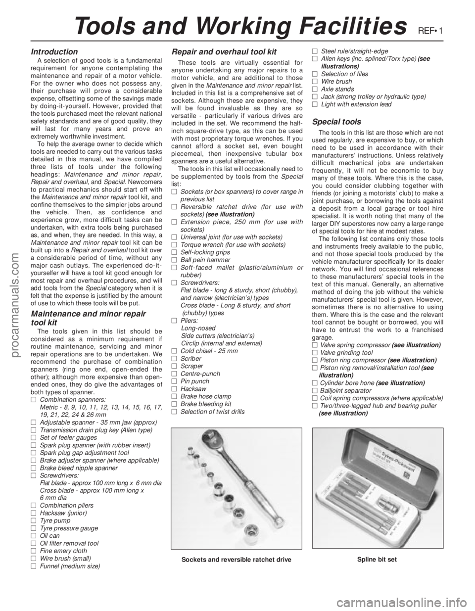
MReversible ratchet drive (for use with
sockets) (see illustration)
MExtension piece, 250 mm (for use with
sockets)
MUniversal joint (for use with sockets)
MTorque wrench (for use with sockets)
MSelf-locking grips
MBall pein hammer
MSoft-faced mallet (plastic/aluminium or
rubber)
MScrewdrivers:
Flat blade - long & sturdy, short (chubby),
and narrow (electrician’s) types
Cross blade - Long & sturdy, and short
(chubby) types
MPliers:
Long-nosed
Side cutters (electrician’s)
Circlip (internal and external)
MCold chisel - 25 mm
MScriber
MScraper
MCentre-punch
MPin punch
MHacksaw
MBrake hose clamp
MBrake bleeding kit
MSelection of twist drillsMSteel rule/straight-edge
MAllen keys (inc. splined/Torx type) (see
illustrations)
MSelection of files
MWire brush
MAxle stands
MJack (strong trolley or hydraulic type)
MLight with extension lead
Special tools
The tools in this list are those which are not
used regularly, are expensive to buy, or which
need to be used in accordance with their
manufacturers’ instructions. Unless relatively
difficult mechanical jobs are undertaken
frequently, it will not be economic to buy
many of these tools. Where this is the case,
you could consider clubbing together with
friends (or joining a motorists’ club) to make a
joint purchase, or borrowing the tools against
a deposit from a local garage or tool hire
specialist. It is worth noting that many of the
larger DIY superstores now carry a large range
of special tools for hire at modest rates.
The following list contains only those tools
and instruments freely available to the public,
and not those special tools produced by the
vehicle manufacturer specifically for its dealer
network. You will find occasional references
to these manufacturers’ special tools in the
text of this manual. Generally, an alternative
method of doing the job without the vehicle
manufacturers’ special tool is given. However,
sometimes there is no alternative to using
them. Where this is the case and the relevant
tool cannot be bought or borrowed, you will
have to entrust the work to a franchised
garage.
MValve spring compressor (see illustration)
MValve grinding tool
MPiston ring compressor (see illustration)
MPiston ring removal/installation tool (see
illustration)
MCylinder bore hone (see illustration)
MBalljoint separator
MCoil spring compressors (where applicable)
MTwo/three-legged hub and bearing puller
(see illustration)
REF•1
Sockets and reversible ratchet driveSpline bit set
Tools and Working Facilities
procarmanuals.com