1993 DODGE TRUCK distance sensor
[x] Cancel search: distance sensorPage 25 of 1502

0 - 6
LUBRICATION
AND
MAINTENANCE
GASOLINE ENGINE MAINTENANCE SCHEDULE
HEAVY
DUTY
CYCLE
Inspection and service is also necessary anytime
a
malfunction is observed or suspected.
When both
time
and mileage
are
Miles (Thousand)
shewn,
follow
the
interval
which occurs first. Kilometers (Thousand) 6
12 18 24
30 36 42 48 54
60 66 72
78
82V2
84 90
96
102 108
When both
time
and mileage
are
Miles (Thousand)
shewn,
follow
the
interval
which occurs first. Kilometers (Thousand) 9.6 19 29
38 48 58 67 77
85 96 106 116
125 132
135
145
154 164
174
Coolant
Condition, Coolant
Hoses/Clamps
X
X X X
X X X X
X X X X
X X X
X X X
Exhaust
System
—
Check
X X X X X X X X X X X
X X X X X
X X
Oil
—
Change
(6
Months)
X X X X X X X
X X
X
X
X
X X X
X X
X
Oil
Filter
—
Change (2nd
Oil
Change)
X X X X
X X
X X
X
Drive Belt Tension
—
Inspect
&
Adjust
X' X
X1
X X' X
Drive Belts (V-Type)
—
Replace
X
Air
Filter/Air
Pump
Air
Filter
—
Replace
X X X
X
Crankcase
Inlet
Air
Filter
(6 &
8
Cyl.
Eng.
Only)
—
Clean
X X
X X
Spark
Plug
—
Replace
X X X
Fuel
Filter
—
Replace as necessary
Coolant
—
Flush/Replace
(36
months)
& 24
months/48
000 km
(30,000
miles)
thereafter
X
EGR
Valve
&
Tube
—
Replace X2
EGR
Tube
—
Clean Passengers
X2
PCV
Valve
—
Replace X2
Vacuum
Emission
Components
—
Replace
X
Ignition Timing
—
Adjust
to
Specs,
as necessary X
Ignition Cables, Distributor Cap
&
Rotor
—
Replace
X
Manifold Heat Control Valve
—
Lubricate
X
Battery
—
Replace X
Oxygen
Sensor
—
Replace
X2
1 For California vehicles, this maintenance is recommended
by
Chrysler Motors
to the
owner but, is not
required
to
maintain the
warranty
on the
air
pump drive
belt.
2 Requires
Emission
Maintenance Reminder Light.
If
so equipped, these parts
are to be
replaced
at the
indicated mileage,
or
when the
emissions
maintenance reminded light remains on continuously
with
the key in the
"on" position, whichever occurs first.
J9100-20
DIESEL
ENGINE
MAINTENANCE
SCHEDULE
HEAVY
DUTY
CYCLE
Inspection
and
service
is
also
necessary
any
time
a
malfunction
is
observed
or
suspected.
Iff both
time
and distance Miles (Thousand)
are listed, use the
interval
that
ends
first. Kilometers (Thousand) 6
12
18 24
30 36 42
4S
54
60 66
72 78
84 90 96
102 108
Iff both
time
and distance Miles (Thousand)
are listed, use the
interval
that
ends
first. Kilometers (Thousand) 9,6 19
29
38 48 58 67
77
85 96 106
116 125 135 145 154
164 174
Coolant
Condition, Coolant
Hoses/Clamps
(12 months)
Coolant
Flush/Replace (36 months) & 24 months/
48 000 km
(30,000
miles)
thereafter
O
Oil—Change
(6 months)
X X X
X X X
X X X X X
X X X X X X
X
Oil Filter—Replace (Every Oil Change)
X X X
X X X
X X
X X X
X
X X X X
X X
Drive Belts—Replace
As
Necessary
X X
X X X X
Air Filter—Replace
X X
X X
Air Filter—Clean (California Only) e
®
• •
Air
Filter
Canister—Clean
o o o
o
Fuel Filter—Service When Necessary
Injection
Pump
Timing & Engine Idle Speed—
Check
& Adjust
©
• 9 • • •
Underhood Rubber/Plastic Components—Inspect/Replace • • • • •
X
— All vehicles
O
— All
vehicles
except
California.
Recommended
for
California.
•
— California only.
Recommended
for all vehicles.
Page 161 of 1502
3
- 34
REAR SUSPENSION
AND
AXLE
• (4) Install the spring U-bolts and tighten the nuts
with the specified torque.
(5) Install the shock absorbers.
(6) Connect the parking brake cables.
(7) Connect the brake lines. Install the hubs and
brake drums. Adjust the wheel bearings (refer to Wheel Bearing Adjustment).
(8) Remove the block from the brake pedal. Bleed
and adjust the brakes.
(9) Connect the drive shaft to the pinion yoke with
the reference marks aligned. Tighten the U-joint clamp bolts to 21 N-m (16 ft. lbs./186 in. lbs.) torque.
(10) Install the rear wheels and tighten the lug
nuts with the specified torque (refer to Group 22,
Wheels And Tires). (11) Raise the rear of the vehicle, remove the sup
ports,
level the vehicle and position the supports. (12) Remove the fill hole plug from the differential
housing cover. Fill the differential housing to the correct level with MOPAR Hypoid Gear Lubricant, or
an equivalent product. Add 4 ounces of MOPAR Hypoid Gear Lubri
cant Additive for Trac-Lok equipped axles. (13) Install the fill hole plug. Remove the supports
and lower the vehicle. (14) Road test the vehicle to evaluate the results of
the repair.
DIFFERENTIAL
DISASSEMBLY
RE MO VA
L/DISA
SSEMBL Y
Remove the RWAL brake sensor
hold-down
bolt and pull the sensor from the differential
housing. The sensor must be removed to prevent damage when disassembling or assembling the differential components.
(1) Note the installation reference letters
stamped on the bearing caps and housing ma
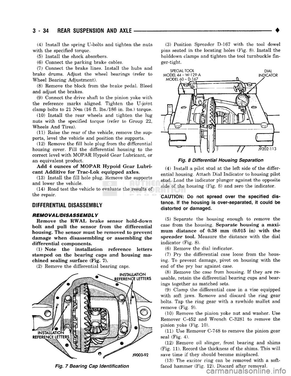
chined sealing surface (Fig. 7). (2) Remove the differential bearing caps.
Fig.
7 Bearing Cap
identification
(3) Position Spreader D-167 with the tool dowel
pins seated in the locating holes (Fig. 8). Install the holddown clamps and tighten the tool turnbuckle fin
ger-tight.
SPECIAL TOOL DIAL
MODEL
44-W-129-A
INDICATOR
Fig.
8
Differential
Housing
Separation
(4) Install a pilot stud at the left side of the differ
ential housing. Attach Dial Indicator to housing pilot
stud. Load the indicator plunger against the opposite
side of the housing (Fig. 8) and zero the indicator.
CAUTION:
Do not
spread
over the specified
dis
tance. If the
housing
is over-separated, it
could
be distorted or
damaged.
(5) Separate the housing enough to remove the
case from the housing. Separate housing a maxi
mum distance of 0.38 mm (0.015 in) with the spreader tool. Measure the distance with the dial
indicator (Fig. 8).
(6) Remove the dial indicator. (7) Pry the differential case loose from the hous
ing. To prevent damage, pivot on housing with the
end of the pry bar against case.
(8) Remove the case from housing. If they are re
usable, retain the differential bearing cups and bear ings together as matched sets.
(9) Clamp the differential case in a vise equipped
with soft jaws. Remove and discard the ring gear
bolts.
Tap the ring gear with a rawhide mallet and
remove (Fig. 9).
(10) Remove the pinion yoke nut and washer. Use
Remover C-452 and Wrench C-3281 to remove the
pinion yoke (Fig. 10).
(11) Use Remover C-748 to remove the pinion gear
seal (Fig. 4).
(12) Remove oil slinger, front bearing and shims
(Fig. 11). Record the thickness of the shims. This will
save time if they should become misplaced.
(13) The excitor ring can be removed with a soft-
faced hammer (Fig. 12). Discard after removal.
Page 251 of 1502
5
- 64
BRAKES
•
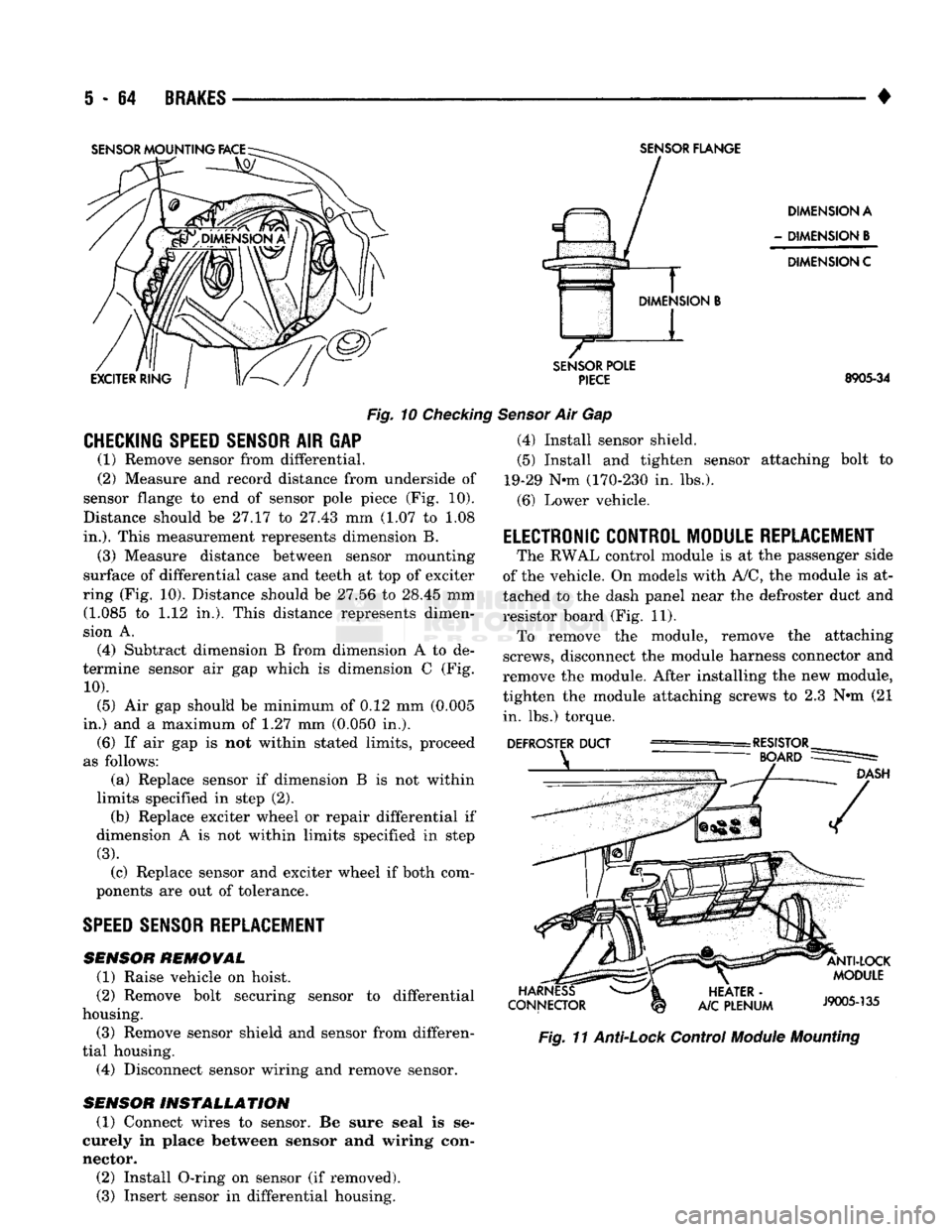
Fig.
10
Checking
CHECKING SPEED SENSOR
AIR GAP (1) Remove sensor from differential.
(2) Measure and record distance from underside of
sensor flange to end of sensor pole piece (Fig. 10).
Distance should be 27.17 to 27.43 mm (1.07 to 1.08
in.).
This measurement represents dimension B.
(3) Measure distance between sensor mounting
surface of differential case and teeth at top of exciter
ring (Fig. 10). Distance should be 27.56 to 28.45 mm (1.085 to 1.12 in,). This distance represents dimen
sion A.
(4) Subtract dimension B from dimension A to de
termine sensor air gap which is dimension C (Fig.
10).
(5) Air gap should be minimum of 0.12 mm (0.005
in.) and a maximum of 1.27 mm (0.050 in.). (6) If air gap is not within stated limits, proceed
as follows: (a) Replace sensor if dimension B is not within
limits specified in step (2). (b) Replace exciter wheel or repair differential if
dimension A is not within limits specified in step
(3).
(c) Replace sensor and exciter wheel if both com
ponents are out of tolerance.
SPEED
SENSOR REPLACEMENT
SENSOR
REMOVAL
(1) Raise vehicle on hoist.
(2) Remove bolt securing sensor to differential
housing.
(3) Remove sensor shield and sensor from differen
tial housing. (4) Disconnect sensor wiring and remove sensor.
SENSOR
INSTALLATION
(1) Connect wires to sensor. Be sure seal is se
curely in place between sensor and wiring con
nector. (2) Install O-ring on sensor (if removed). (3) Insert sensor in differential housing.
SENSOR
FLANGE
DIMENSION A
-
DIMENSION
B
DIMENSION C
SENSOR
POLE
PIECE
8905-34
Sensor
Air Gap (4) Install sensor shield.
(5) Install and tighten sensor attaching bolt to
19-29 Nnn (170-230 in. lbs.).
(6) Lower vehicle.
ELECTRONIC CONTROL MODULE REPLACEMENT
The RWAL control module is at the passenger side
of the vehicle. On models with A/C, the module is at
tached to the dash panel near the defroster duct and
resistor board (Fig. 11). To remove the module, remove the attaching
screws, disconnect the module harness connector and
remove the module. After installing the new module,
tighten the module attaching screws to 2.3 N»m (21 in. lbs.) torque.
Fig.
11
Anti-Lock
Control
Module
Mounting
Page 353 of 1502
8D
- 2
IGNITION
SYSTEMS
•
A/C
CLUTCH RELAY STARTER RELAY
DATA LINK CONTROL
CONNECTOR
MODULE J9314-164
Fig.
1
Auto
Shut Down
Relay
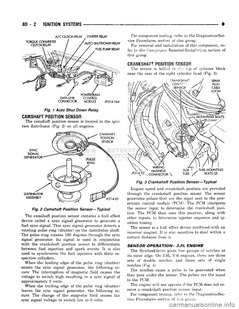
CAMSHAFT POSITION SENSOR
The camshaft position sensor is located in the igni
tion distributor (Fig. 2) on all engines.
Fig.
2 Camshaft Position
Sensor—
Typical
The camshaft position sensor contains a hall effect
device called a sync signal generator to generate a
fuel sync signal. This sync signal generator detects a
rotating pulse ring (shutter) on the distributor shaft.
The pulse ring rotates 180 degrees through the sync signal generator. Its signal is used in conjunction
with the crankshaft position sensor to differentiate
between fuel injection and spark events. It is also
used to synchronize the fuel injectors with their re spective cylinders.
When the leading edge of the pulse ring (shutter)
enters the sync signal generator, the following oc
curs:
The interruption of magnetic field causes the
voltage to switch high resulting in a sync signal of approximately 5 volts.
When the trailing edge of the pulse ring (shutter)
leaves the sync signal generator, the following oc
curs:
The change of the magnetic field causes the sync signal voltage to switch low to 0 volts. For component testing, refer to the Diagnostics/Ser
vice Procedures section of this group. For removal and installation of this component, re
fer to the Component Removal/Installation section of this group.
CRANKSHAFT
POSITION
SENSOR
The sensor is bolted to the top of cylinder block
near the rear of the right cylinder head (Fig. 3).
Fig.
3 Crankshaft Position Sensor—Typical
*
Engine speed and crankshaft position are provided
through the crankshaft position sensor. The sensor generates pulses that are the input sent to the pow
ertrain control module (PCM). The PCM interprets
the sensor input to determine the crankshaft posi
tion. The PCM then uses this position, along with other inputs, to determine injector sequence and ig
nition timing.
The sensor is a hall effect device combined with an
internal magnet. It is also sensitive to steel within a
certain distance from it.
SENSOR
OPERATION-3.9L
ENGINE
The flywheel/drive plate has groups of notches at
its outer edge. On 3.9L V-6 engines, there are three sets of double notches and three sets of single
notches (Fig.
4).
The notches cause a pulse to be generated when
they pass under the sensor. The pulses are the input to the PCM.
The engine will not operate if the PCM does not re
ceive a crankshaft position sensor input.
For component testing, refer to the Diagnostics/Ser
vice Procedures section of this group.
Page 382 of 1502
• • ^ ^ ^ INSTRUMENT PANEL AND GAUGES 8E - 1
CONTENTS
page
CLUSTER AND GAUGE SERVICE PROCEDURES . 12
CLUSTER AND GAUGE TEST PROCEDURES .. i
GENERAL INFORMATION . 1
page
MESSAGE CENTER-DIESEL ENGINE ........ 4
MESSAGE CENTER-GAS ENGINE .......... 3
SWITCH
AND PANEL COMPONENT SERVICE . 16
GENERAL
INFORMATION
INDEX
page
Generator
Indicating
System
2
Distance
Sensor
2
Electronic
Digital
Clock
3
Fuel
Level
Indicating
System
1
page
Malfunction
Indicator
(Check
Engine)
3
Oil
Pressure
Warning
Lamp
................. 2
Speedometer/Odometer
System
2
Temperature
and Oil
Indicating
System
......... 2
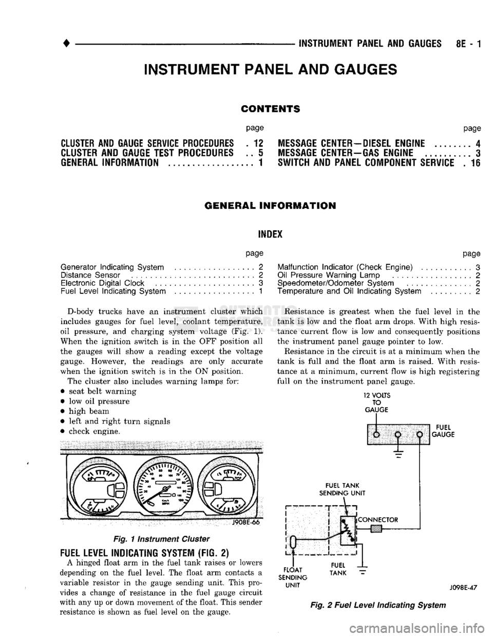
D-body trucks have an instrument cluster which
includes gauges for fuel level, coolant temperature,
oil pressure, and charging system voltage (Fig. 1).
When the ignition switch is in the OFF position all
the gauges will show a reading except the voltage gauge. However, the readings are only accurate
when the ignition switch is in the ON position.
The cluster also includes warning lamps for:
• seat belt warning
• low oil pressure
• high beam
• left and right turn signals
• check engine. J908E-66
Fig.
11nstrument
Cluster
FUEL LEVEL INDICATING SYSTEM (FIG. 2)
A hinged float arm in the fuel tank raises or lowers
depending on the fuel level. The float arm contacts a
variable resistor in the gauge sending unit. This pro
vides a change of resistance in the fuel gauge circuit
with any up or down movement of the float. This sender
resistance is shown as fuel level on the gauge. Resistance is greatest when the fuel level in the
tank is low and the float arm drops. With high resis
tance current flow is low and consequently positions
the instrument panel gauge pointer to low.
Resistance in the circuit is at a minimum when the
tank is full and the float arm is raised. With resis
tance at a minimum, current flow is high registering
full on the instrument panel gauge.
12
VOLTS
TO
GAUGE
IP
FUEL
TANK
SENDING
UNIT
FLOAT
SENDING
UNIT
1:
1
j
^
fCONNECTOR
!g|yj-»—
FUEL
GAUGE
FUEL
TANK
J098E-47
Fig.
2
Fuel
Level
Indicating
System
INSTRUMENT PANEL AND GAUGES
Page 383 of 1502
8E
- 2
INSTRUMENT PANEL
AND
GAUGES
•
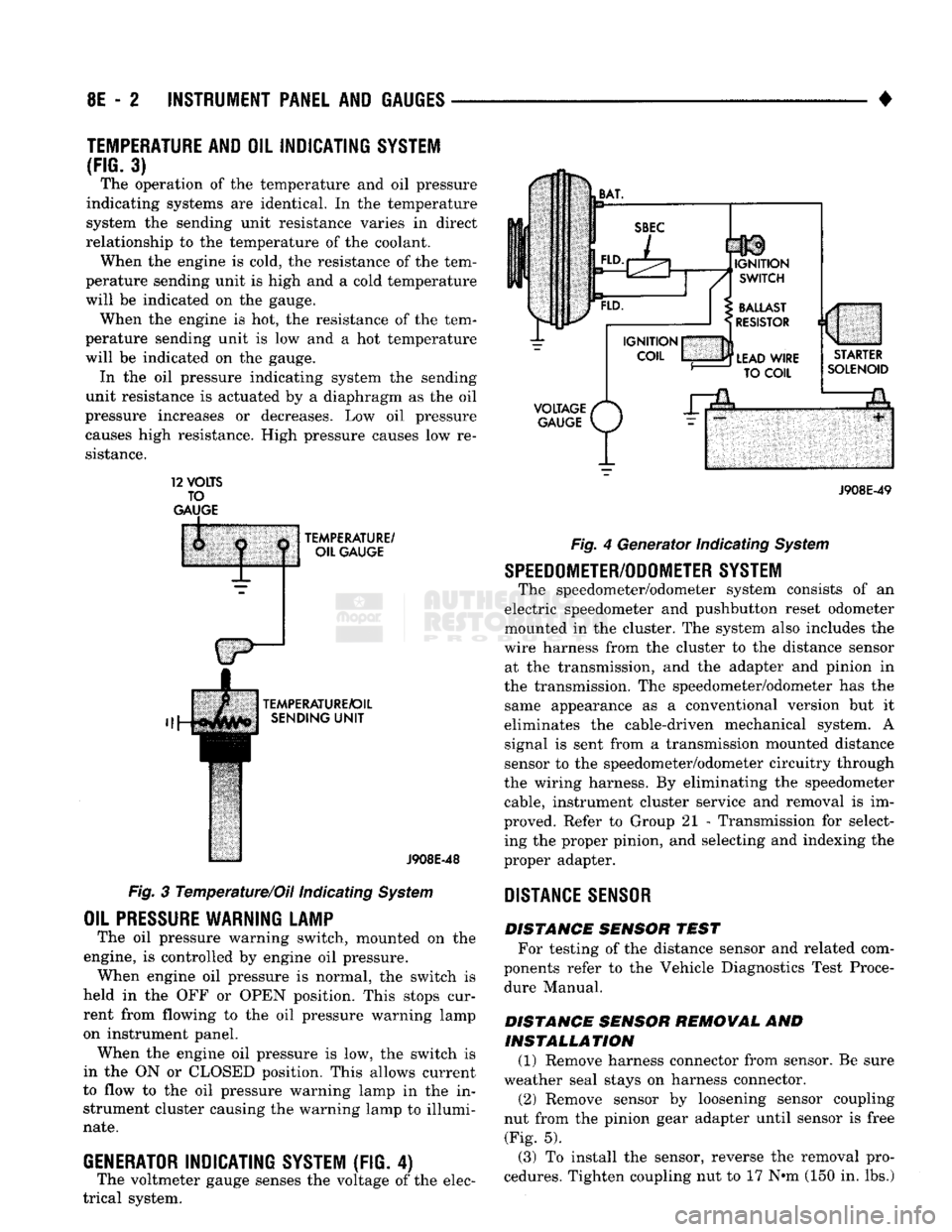
TEMPERATURE AND
OIL
INDICATING SYSTEM
(FIG.
3) The operation of the temperature and oil pressure
indicating systems are identical. In the temperature
system the sending unit resistance varies in direct
relationship to the temperature of the coolant. When the engine is cold, the resistance of the tem
perature sending unit is high and a cold temperature
will be indicated on the gauge. When the engine is hot, the resistance of the tem
perature sending unit is low and a hot temperature
will be indicated on the gauge. In the oil pressure indicating system the sending
unit resistance is actuated by a diaphragm as the oil
pressure increases or decreases. Low oil pressure causes high resistance. High pressure causes low re
sistance. 12
VOLTS
TO
GAUGE
TEMPERATURE/
OIL GAUGE
TEMPERATURE/OIL SENDING
UNIT
J908E-48
Fig. 3 Temperature/Oil indicating System
OIL
PRESSURE
WARNING LAMP
The oil pressure warning switch, mounted on the
engine, is controlled by engine oil pressure. When engine oil pressure is normal, the switch is
held in the OFF or OPEN position. This stops cur
rent from flowing to the oil pressure warning lamp
on instrument panel. When the engine oil pressure is low, the switch is
in the ON or CLOSED position. This allows current
to flow to the oil pressure warning lamp in the in strument cluster causing the warning lamp to illumi
nate.
GENERATOR
INDICATING
SYSTEM
(FIG. 4)
The voltmeter gauge senses the voltage of the elec
trical system.
VOLTAGE
/*
GAUGE
P/
J908E-49 Fig. 4 Generator Indicating System
SPEEDOMETER/ODOMETER SYSTEM
The speedometer/odometer system consists of an
electric speedometer and pushbutton reset odometer
mounted in the cluster. The system also includes the
wire harness from the cluster to the distance sensor at the transmission, and the adapter and pinion in
the transmission. The speedometer/odometer has the same appearance as a conventional version but it
eliminates the cable-driven mechanical system. A signal is sent from a transmission mounted distance
sensor to the speedometer/odometer circuitry through
the wiring harness. By eliminating the speedometer cable, instrument cluster service and removal is im
proved. Refer to Group 21 - Transmission for select ing the proper pinion, and selecting and indexing the
proper adapter.
DISTANCE
SENSOR
DISTANCE SENSOR TEST For testing of the distance sensor and related com
ponents refer to the Vehicle Diagnostics Test Proce dure Manual.
DISTANCE SENSOR REMOVAL AND INSTALLATION (1) Remove harness connector from sensor. Be sure
weather seal stays on harness connector. (2) Remove sensor by loosening sensor coupling
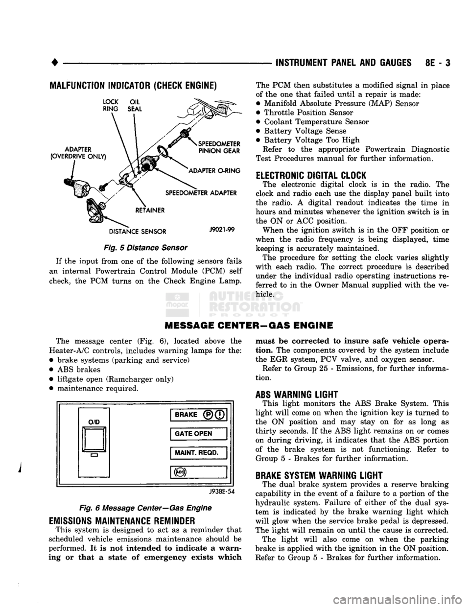
nut from the pinion gear adapter until sensor is free (Fig. 5).
(3) To install the sensor, reverse the removal pro
cedures. Tighten coupling nut to 17 N»m (150 in. lbs.)
Page 384 of 1502
•
INSTRUMENT PANEL
AND
GAUGES
8E - 3
MALFUNCTION INDICATOR (CHECK ENGINE)
Fig.
5
Distance Sensor
If
the
input from
one of the
following sensors fails
an internal Powertrain Control Module
(PCM)
self
check,
the PCM
turns
on the
Check Engine Lamp. The
PCM
then substitutes
a
modified signal
in
place
of
the one
that failed until
a
repair
is
made:
• Manifold Absolute Pressure (MAP) Sensor
• Throttle Position Sensor
• Coolant Temperature Sensor
• Battery Voltage Sense
• Battery Voltage
Too
High
Refer
to the
appropriate Powertrain Diagnostic
Test Procedures manual
for
further information.
ELECTRONIC DIGITAL CLOCK
The electronic digital clock
is in the
radio.
The
clock
and
radio each
use the
display panel built into
the radio.
A
digital readout indicates
the
time
in
hours
and
minutes whenever
the
ignition switch
is in
the
ON or ACC
position. When
the
ignition switch
is in the OFF
position
or
when
the
radio frequency
is
being displayed, time keeping
is
accurately maintained. The procedure
for
setting
the
clock varies slightly
with each radio.
The
correct procedure
is
described under
the
individual radio operating instructions
re
ferred
to in the
Owner Manual supplied with
the ve
hicle.
MESSAGE CENTER—GAS ENGINE
The message center
(Fig. 6),
located above
the
Heater-A/C controls, includes warning lamps
for the:
• brake systems (parking
and
service)
•
ABS
brakes • liftgate open (Ramcharger only)
• maintenance required.
O/D
BRAKE
(P)(7
GATE OPEN
MAINT
REQD.
J938E-54
Fig.
6
Message Center—Gas Engine
EMISSIONS
MAINTENANCE REMINDER
This system
is
designed
to act as a
reminder that
scheduled vehicle emissions maintenance should
be
performed.
It is not
intended
to
indicate
a
warn
ing
or
that
a
state
of
emergency exists which must
be
corrected
to
insure safe vehicle opera
tion.
The
components covered
by the
system include
the
EGR
system,
PCV
valve,
and
oxygen sensor. Refer
to
Group
25 -
Emissions,
for
further informa
tion.
ABS
WARNING
LIGHT
This light monitors
the ABS
Brake System. This
light will come
on
when
the
ignition
key is
turned
to
the
ON
position
and may
stay
on for as
long
as
thirty seconds.
If the ABS
light remains
on or
comes on during driving,
it
indicates that
the ABS
portion
of
the
brake system
is not
functioning. Refer
to
Group
5 -
Brakes
for
further information.
BRAKE
SYSTEM WARNING
LIGHT
The dual brake system provides
a
reserve braking
capability
in the
event
of a
failure
to a
portion
of the
hydraulic system. Failure
of
either
of the
dual sys
tem
is
indicated
by the
brake warning light which
will glow when
the
service brake pedal
is
depressed.
The light will remain
on
until
the
cause
is
corrected. The light will also come
on
when
the
parking
brake
is
applied with
the
ignition
in the ON
position.
Refer
to
Group
5 -
Brakes
for
further information.
Page 392 of 1502
•
Fig.
16
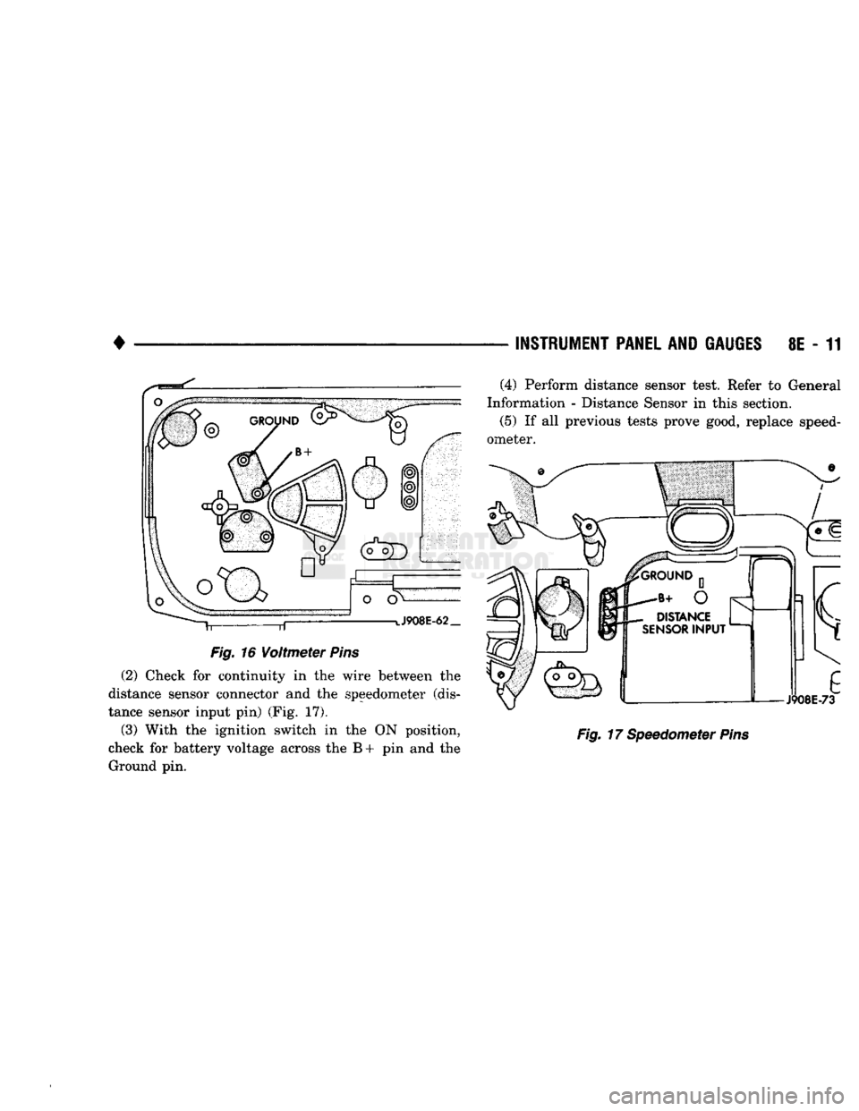
Voltmeter
Pins
(2) Check for continuity in the wire between the
distance sensor connector and the speedometer (dis
tance sensor input pin) (Fig. 17).
(3) With the ignition switch in the ON position,
check for battery voltage across the B + pin and the Ground pin. —
INSTRUMENT PANEL
AND
GAUGES
8E - 11
Fig.
17 Speedometer
Pins
(4) Perform distance sensor test. Refer to General
Information - Distance Sensor in this section.
(5)
If all previous tests prove good, replace speed
ometer.