1993 DODGE TRUCK engine oil
[x] Cancel search: engine oilPage 1147 of 1502
21 - 146
AUTOMATIC
TRANSMISSION REMOVAL
AND
INSTALLATION
• • Use a D.C. welder set at straight polarity, or use
an A.C. welder if the proper electrode is available
• Use 1/8 inch diameter welding rod and a welding
current of 80 to 125 amps. • Direct arc at intersection of gear and front cover at
an angle of 45° from rear face of gear.
(6)
Weld new ring gear to torque converter front
cover. Take care to place same amount of weld mate
rial (or as nearly as possible) in original weld loca
tions.
This is essential in maintaining converter
balance. Position welds alternately on opposite sides of converter and ring gear to minimize distortion.
(7) Inspect gear teeth and remove any nicks, raised
metal, weld spatter, or rough surfaces.
PUMP
OIL
SEAL
Seal
Removal
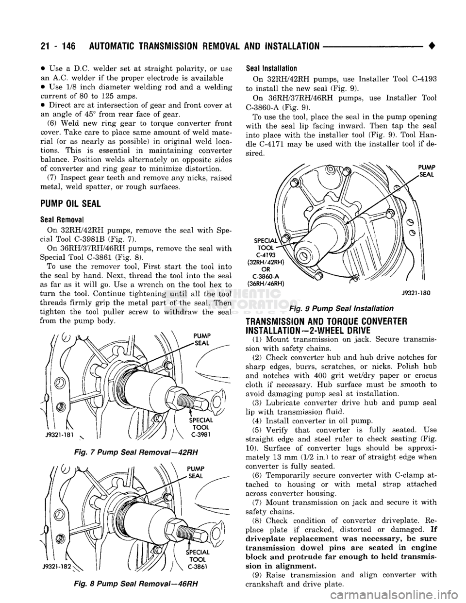
On 32RH/42RH pumps, remove the seal with Spe
cial Tool C-3981B (Fig. 7).
On 36RH/37RH/46RH pumps, remove the seal with
Special Tool C-3861 (Fig. 8). To use the remover tool, First start the tool into
the seal by hand. Next, thread the tool into the seal as far as it will go. Use a wrench on the tool hex to
turn the tool. Continue tightening until all the tool
threads firmly grip the metal part of the seal. Then
tighten the tool puller screw to withdraw the seal
from the pump body.
Fig. 7 Pump Seal Removal—42RH Fig. 8 Pump Seal Removal—46RH
Seal
Installation
On 32RH/42RH pumps, use Installer Tool C-4193
to install the new seal (Fig. 9).
On 36RH/37RH/46RH pumps, use Installer Tool
C-3860-A (Fig. 9).
To use the tool, place the seal in the pump opening
with the seal lip facing inward. Then tap the seal into place with the installer tool (Fig. 9). Tool Han
dle C-4171 may be used with the installer tool if de sired.
J932M80
Fig. 9 Pump Seal Installation
TRANSMISSION
AND TORQUE CONVERTER INSTALLATION—2-WHEEL DRIVE
(1) Mount transmission on jack. Secure transmis
sion with safety chains. (2) Check converter hub and hub drive notches for
sharp edges, burrs, scratches, or nicks. Polish hub
and notches with 400 grit wet/dry paper or crocus
cloth if necessary. Hub surface must be smooth to avoid damaging pump seal at installation. (3) Lubricate converter drive hub and pump seal
lip with transmission fluid. (4) Install converter in oil pump.
(5) Verify that converter is fully seated. Use
straight edge and steel ruler to check seating (Fig.
10).
Surface of converter lugs should be approxi
mately 13 mm (1/2 in.) to rear of straight edge when
converter is fully seated. (6) Temporarily secure converter with C-clamp at
tached to housing or with metal strap attached across converter housing. (7) Mount transmission on jack and secure it with
safety chains. (8) Check condition of converter driveplate. Re
place plate if cracked, distorted or damaged. If driveplate replacement was necessary, be sure
transmission dowel pins are seated in engine
block and protrude far enough to held transmis sion in alignment. (9) Raise transmission and align converter with
crankshaft and drive plate.
Page 1343 of 1502
21
- 342
NP205 TRANSFER CASE
•
NP205
TRANSFER CASE
INDEX
page
General
Information
342
Recommended Lubricants
342
Service Diagnosis
342
Shift
Linkage
Adjustment
344
Speedometer Service
345
GENERAL
INFORMATION
The NP205 transfer case
is a
heavy duty, part-time
unit with constant mesh, helical gears.
The
gears
are
mounted
in a
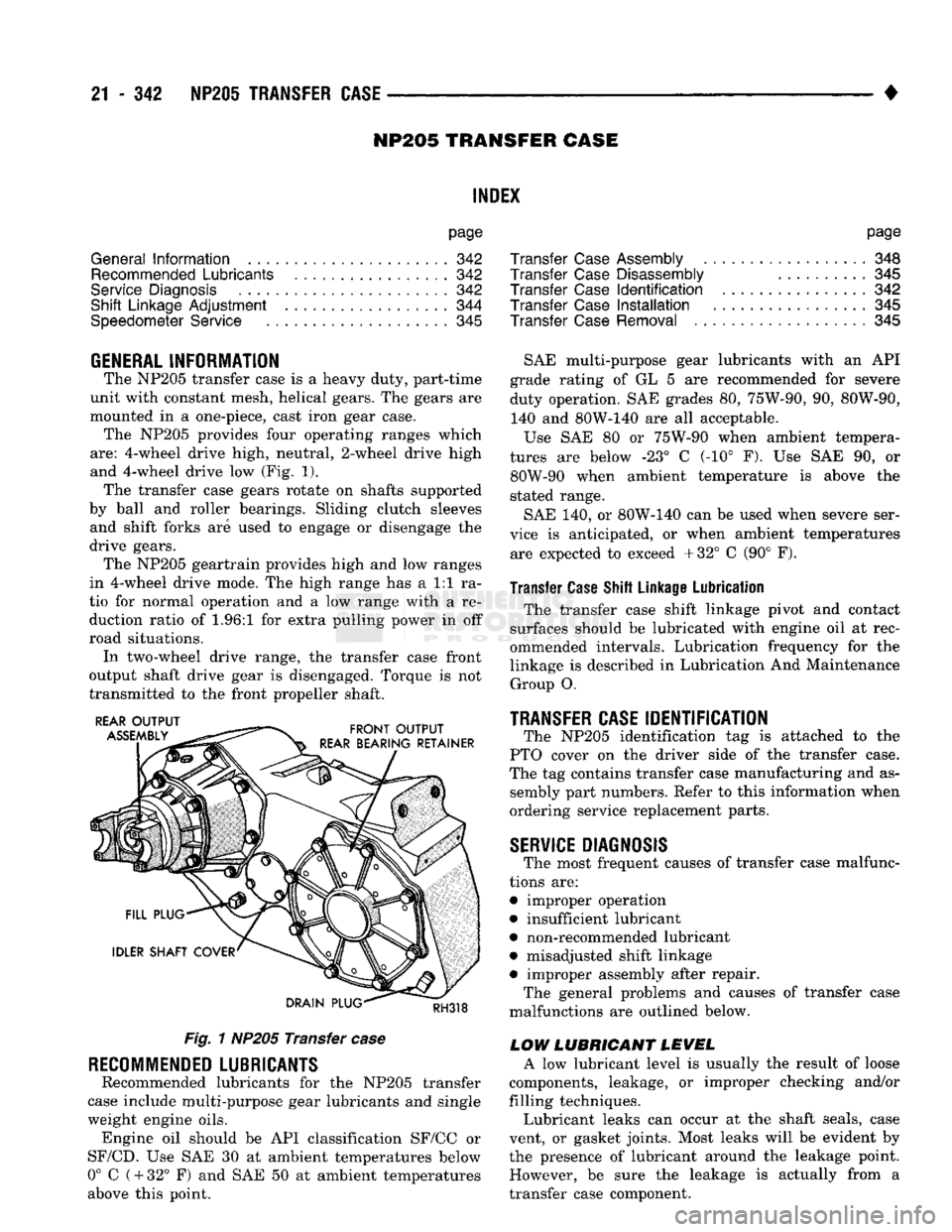
one-piece, cast iron gear case. The NP205 provides four operating ranges which
are:
4-wheel drive high, neutral, 2-wheel drive high
and 4-wheel drive
low (Fig. 1).
The transfer case gears rotate
on
shafts supported
by ball
and
roller bearings. Sliding clutch sleeves and shift forks
are
used
to
engage
or
disengage
the
drive gears. The NP205 geartrain provides high
and low
ranges
in 4-wheel drive mode.
The
high range
has a 1:1 ra
tio
for
normal operation
and a low
range with
a re
duction ratio
of 1.96:1 for
extra pulling power
in off
road situations. In two-wheel drive range,
the
transfer case front
output shaft drive gear
is
disengaged. Torque
is not
transmitted
to the
front propeller shaft.
Fig.
1
NP205 Transfer
case
RECOMMENDED
LUBRICANTS
Recommended lubricants
for the
NP205 transfer
case include multi-purpose gear lubricants
and
single
weight engine oils. Engine
oil
should
be API
classification SF/CC
or
SF/CD.
Use SAE 30 at
ambient temperatures below
0°
C
(
+
32°
F) and SAE 50 at
ambient temperatures
above this point.
page
Transfer
Case
Assembly
348
Transfer
Case
Disassembly
..........
345
Transfer
Case
Identification
342
Transfer
Case
Installation
345
Transfer
Case
Removal
345
SAE multi-purpose gear lubricants with
an API
grade rating
of GL 5 are
recommended
for
severe
duty operation.
SAE
grades
80,
75W-90,
90,
80W-90, 140
and
80W-140
are all
acceptable.
Use
SAE 80 or
75W-90 when ambient tempera
tures
are
below
-23° C (-10° F). Use SAE 90, or
80W-90 when ambient temperature
is
above
the
stated range.
SAE
140, or
80W-140
can be
used when severe ser
vice
is
anticipated,
or
when ambient temperatures are expected
to
exceed +32°
C (90° F).
Transfer Case Shift Linkage Lubrication
The transfer case shift linkage pivot
and
contact
surfaces should
be
lubricated with engine
oil at
rec
ommended intervals. Lubrication frequency
for the
linkage
is
described
in
Lubrication
And
Maintenance Group
O.
TRANSFER CASE
IDENTIFICATION
The NP205 identification
tag is
attached
to the
PTO cover
on the
driver side
of the
transfer case.
The
tag
contains transfer case manufacturing
and as
sembly part numbers. Refer
to
this information when
ordering service replacement parts.
SERVICE
DIAGNOSIS
The most frequent causes
of
transfer case malfunc
tions
are:
• improper operation
• insufficient lubricant
• non-recommended lubricant
• misadjusted shift linkage
• improper assembly after repair. The general problems
and
causes
of
transfer case
malfunctions
are
outlined below.
LOW LUBRICANT LEVEL
A
low
lubricant level
is
usually
the
result
of
loose
components, leakage,
or
improper checking and/or
filling techniques. Lubricant leaks
can
occur
at the
shaft seals, case
vent,
or
gasket joints. Most leaks will
be
evident
by
the presence
of
lubricant around
the
leakage point. However,
be
sure
the
leakage
is
actually from
a
transfer case component.
Page 1346 of 1502
•
NP20I
TRANSFER CASE
21 - 34i (5) Verify that transfer case range lever is in Neu
tral.
(6) Move shift lever bracket forward and retighten
bracket bolts (Fig. 3). Shift rod should not bind in shift lever and range lever. Rod should be slip-fit
both levers. (7) Shift transfer case into 4H range. Shift rod
should now be tension-fit in each lever. Shift lever
should be in 4H detent in gate and range lever should be fully into 4H position.
(8) Shift transfer case into 2H and 4L ranges to
verify correct adjustment.
SPEEDOMETER SERVICE
The speedometer driven gear, adapter and vehicle
speed sensor can be serviced with the transfer case in
the vehicle.
SPEEDOMETER COMPONENT REMOVAL/
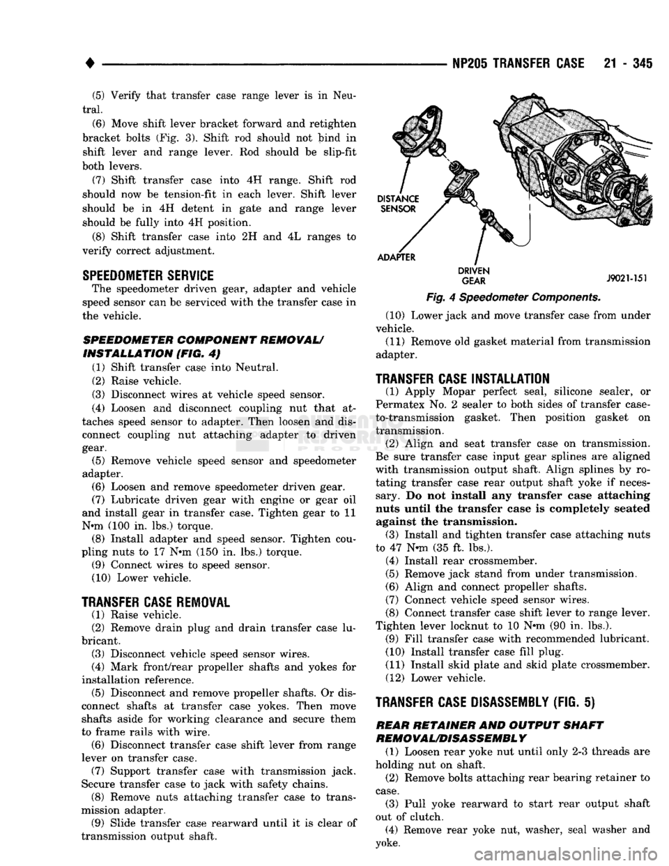
INSTALLATION (FIG. 4) (1) Shift transfer case into Neutral.
(2) Raise vehicle.
(3) Disconnect wires at vehicle speed sensor.
(4) Loosen and disconnect coupling nut that at
taches speed sensor to adapter. Then loosen and dis connect coupling nut attaching adapter to driven
gear.
(5) Remove vehicle speed sensor and speedometer
adapter. (6) Loosen and remove speedometer driven gear.
(7) Lubricate driven gear with engine or gear oil
and install gear in transfer case. Tighten gear to 11
N*m (100 in. lbs.) torque. (8) Install adapter and speed sensor. Tighten cou
pling nuts to 17 N»m (150 in. lbs.) torque. (9) Connect wires to speed sensor.
(10) Lower vehicle.
TRANSFER CASE
REMOVAL
(1) Raise vehicle.
(2) Remove drain plug and drain transfer case lu
bricant. (3) Disconnect vehicle speed sensor wires.
(4) Mark front/rear propeller shafts and yokes for
installation reference. (5) Disconnect and remove propeller shafts. Or dis
connect shafts at transfer case yokes. Then move shafts aside for working clearance and secure them
to frame rails with wire. (6) Disconnect transfer case shift lever from range
lever on transfer case. (7) Support transfer case with transmission jack.
Secure transfer case to jack with safety chains. (8) Remove nuts attaching transfer case to trans
mission adapter. (9) Slide transfer case rearward until it is clear of
transmission output shaft.
DISTANCE
SENSOR
ADAPTER
DRIVEN
GEAR
J9021-151
Fig.
4 Speedometer Components.
(10) Lower jack and move transfer case from under
vehicle.
(11) Remove old gasket material from transmission
adapter.
TRANSFER CASE
INSTALLATION
(1) Apply Mopar perfect seal, silicone sealer, or
Permatex No. 2 sealer to both sides of transfer case-
to-transmission gasket. Then position gasket on
transmission. (2) Align and seat transfer case on transmission.
Be sure transfer case input gear splines are aligned
with transmission output shaft. Align splines by ro
tating transfer case rear output shaft yoke if neces sary. Do not install any transfer case attaching
nuts until the transfer case is completely seated against the transmission. (3) Install and tighten transfer case attaching nuts
to 47 N*m (35 ft. lbs.). (4) Install rear crossmember.
(5) Remove jack stand from under transmission.
(6) Align and connect propeller shafts.
(7) Connect vehicle speed sensor wires.
(8) Connect transfer case shift lever to range lever.
Tighten lever locknut to 10 N»m (90 in. lbs.). (9) Fill transfer case with recommended lubricant.
(10) Install transfer case fill plug.
(11) Install skid plate and skid plate crossmember.
(12) Lower vehicle.
TRANSFER CASE DISASSEMBLY
(FIG.
S) REAR RETAINER AND OUTPUT SHAFT
REMOVAL/DISASSEMBL
Y
(1) Loosen rear yoke nut until only 2-3 threads are
holding nut on shaft. (2) Remove bolts attaching rear bearing retainer to
case.
(3) Pull yoke rearward to start rear output shaft
out of clutch. (4) Remove rear yoke nut, washer, seal washer and
yoke.
Page 1389 of 1502
23
- 6
BODY
COMPONENTS
•
INSTRUMENT
PANEL
COWL
PANEL
REGULATOR
BRACKET
J9123-437
Fig.
14 Release Cable Handle Bracket &
Diesel
Engine
Speed
Control Regulator Bracket (4) If a replacement hood is being installed, trans
fer the underhood lamp and the insulator panel (Fig.
17).
(5) Test the hood hinges for correct operation.
(6) Lubricate the hood hinges with engine oil.
INSTALLATION
(1) With the aid of an assistant, position the hood
on the vehicle. Align the hood bolt holes with the
hinge arm holes. Install and finger-tighten the bolts. (2) Align the hood, the latch, and the striker.
HINGE
REPLACEMENT
REMOVAL
If both hinges are being replaced, remove the
hood and both hinges as a unit. If only one
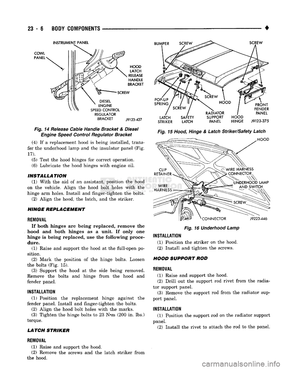
hinge is being replaced, use the following proce dure. (1) Raise and support the hood at the full-open po
sition. (2) Mark the position of the hinge bolts. Loosen
the bolts (Fig. 15). (3) Support the hood at the side being removed.
Remove the bolts and hinge from the hood and
fender panel.
INSTALLATION
(1) Position the replacement hinge against the
fender panel. Install and finger-tighten the bolts. (2) Align the hood bolt holes with the marks.
(3) Tighten the hinge bolts to 23 N-m (200 in. lbs.)
torque.
LATCH STRIKER
LATCH SAFETY SUPPORT HOOD
STRIKER
LATCH PANEL HINGE
J9123-375
Fig.
16
Underhood
Lamp
INSTALLATION
(1) Position the striker on the hood.
(2) Install and tighten the screws.
HOOD SUPPORT ROD
REMOVAL
(1) Raise and support the hood.
(2) Drill out the support rod rivet from the radia
tor support panel. (3) Remove the support rod from the radiator sup
port panel.
INSTALLATION
(1) Position the support rod on the radiator support
panel. (2) Install the rivet to attach the rod to the panel.
REMOVAL
(1) Raise and support the hood.
(2) Remove the screws and the latch striker from
the hood.
Page 1404 of 1502
•
BODY COMPONENTS
23
- 21
DOORS
INDEX
page
Complete
Door
..........................
22
Door
Adjustment
. 21
Door Inside Handle
. 26
Door
Latch
27
Door
Latch
Striker
25
Door Outside Handle
26
Door
Trim
Panel/Waterdam
21
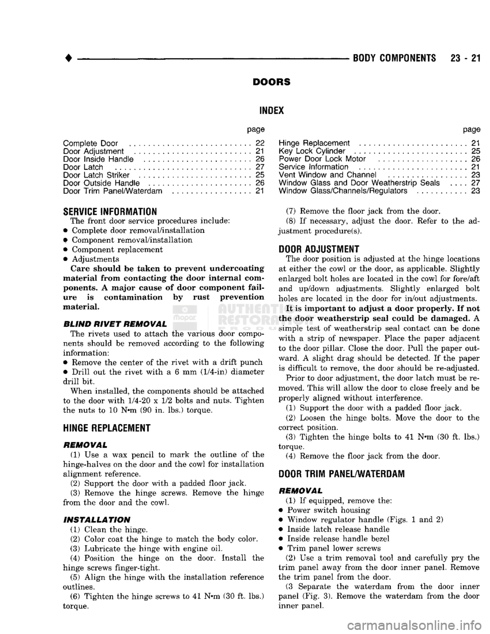
SERVICE INFORMATION
The front door service procedures include:
• Complete door removal/installation
f
Component removal/installation • Component replacement • Adjustments Care should
be
taken
to
prevent undercoating
material from contacting
the
door internal com ponents.
A
major cause
of
door component fail
ure
is
contamination
by
rust prevention
material.
BLIND
RIVET REMOVAL The rivets used
to
attach
the
various door compo
nents should
be
removed according
to the
following
information:
• Remove
the
center
of the
rivet with
a
drift punch • Drill
out the
rivet with
a 6 mm
(1/4-in) diameter
drill
bit.
When installed,
the
components should
be
attached
to
the
door with
1/4-20
x 1/2
bolts
and
nuts. Tighten
the nuts
to 10 N«m (90 in. lbs.)
torque.
HINGE
REPLACEMENT
REMOVAL (1)
Use a wax
pencil
to
mark
the
outline
of the
hinge-halves
on the
door
and the
cowl
for
installation alignment reference.
(2) Support
the
door with
a
padded floor jack.
(3) Remove
the
hinge screws. Remove
the
hinge
from
the
door
and the
cowl.
INSTALLATION (1) Clean
the
hinge.
(2) Color coat
the
hinge
to
match
the
body color.
(3) Lubricate
the
hinge with engine
oil.
(4) Position
the
hinge
on the
door. Install
the
hinge screws finger-tight.
(5) Align
the
hinge with
the
installation reference
outlines.
(6)
Tighten
the
hinge screws
to 41
N»m
(30 ft. lbs.)
torque.
page
Hinge Replacement
, 21
Key
Lock
Cylinder
........................
25
Power Door Lock Motor
26
Service
Information
21
Vent Window
and
Channel
23
Window
Glass
and
Door
Weatherstrip
Seals
.... 27
Window Glass/Channels/Regulators
...........
23
(7) Remove
the
floor jack from
the
door.
(8)
If
necessary, adjust
the
door. Refer
to the ad
justment procedure(s).
DOOR
ADJUSTMENT
The door position
is
adjusted
at the
hinge locations
at either
the
cowl
or the
door,
as
applicable. Slightly
enlarged bolt holes
are
located
in the
cowl
for
fore/aft and up/down adjustments. Slightly enlarged bolt
holes
are
located
in the
door
for
in/out adjustments. It
is
important
to
adjust
a
door properly.
If not
the door weatherstrip seal could
be
damaged.
A
simple test
of
weatherstrip seal contact
can be
done
with
a
strip
of
newspaper. Place
the
paper adjacent
to
the
door pillar. Close
the
door. Pull
the
paper out
ward.
A
slight drag should
be
detected.
If the
paper is difficult
to
remove,
the
door should
be
re-adjusted.
Prior
to
door adjustment,
the
door latch must
be re
moved. This will allow
the
door
to
close freely
and be
properly aligned without interference.
(1) Support
the
door with
a
padded floor jack.
(2) Loosen
the
hinge bolts. Move
the
door
to the
correct position. (3) Tighten
the
hinge bolts
to 41 N«m (30 ft. lbs.)
torque. (4) Remove
the
floor jack from
the
door.
DOOR
TRIM
PANEL/WATERDAM
REMOVAL
(1)
If
equipped, remove
the:
• Power switch housing
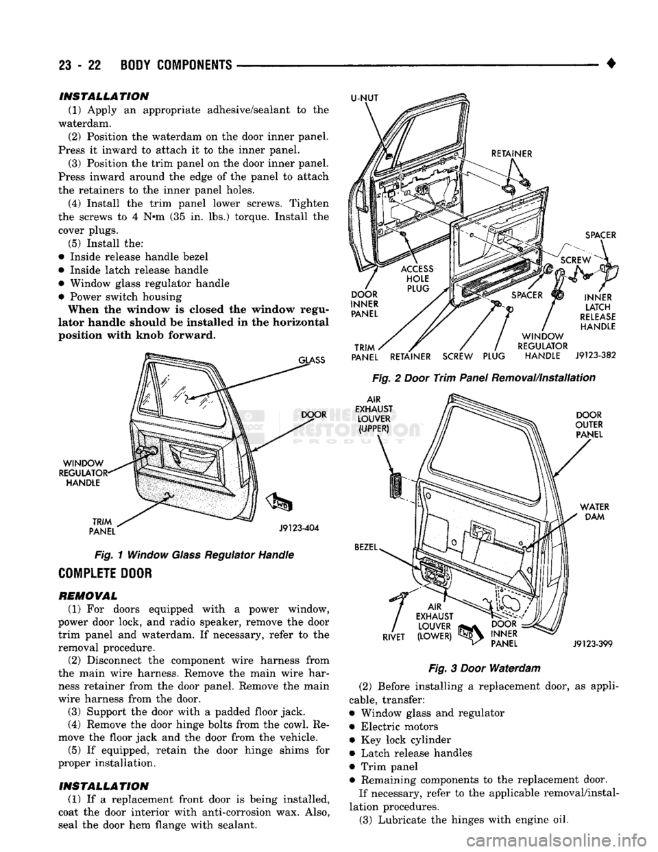
• Window regulator handle (Figs.
1 and 2)
• Inside latch release handle • Inside release handle bezel
• Trim panel lower screws (2)
Use a
trim removal tool
and
carefully
pry the
trim panel away from
the
door inner panel. Remove
the trim panel from
the
door.
(3 Separate
the
waterdam from
the
door inner
panel
(Fig. 3).
Remove
the
waterdam from
the
door inner panel.
Page 1405 of 1502
23
- 22
BODY COMPONENTS
•
INSTALLATION
(1) Apply an appropriate adhesive/sealant to the
waterdam. (2) Position the waterdam on the door inner panel.
Press it inward to attach it to the inner panel. (3) Position the trim panel on the door inner panel.
Press inward around the edge of the panel to attach
the retainers to the inner panel holes. (4) Install the trim panel lower screws. Tighten
the screws to 4 N»m (35 in. lbs.) torque. Install the cover plugs.
(5) Install the:
• Inside release handle bezel
• Inside latch release handle
• Window glass regulator handle
• Power switch housing When the window is closed the window regu
lator handle should be installed in the horizontal position with knob forward.
GLASS
U-NUT
WINDOW
REGULATOR' HANDLE
TRIM
PANEL DOOR
J9123-404
Fig.
1 Window
Glass
Regulator Handle
COMPLETE DOOR
REMOVAL
(1) For doors equipped with a power window,
power door lock, and radio speaker, remove the door trim panel and waterdam. If necessary, refer to the
removal procedure.
(2) Disconnect the component wire harness from
the main wire harness. Remove the main wire har ness retainer from the door panel. Remove the main
wire harness from the door.
(3) Support the door with a padded floor jack.
(4) Remove the door hinge bolts from the cowl. Re
move the floor jack and the door from the vehicle.
(5) If equipped, retain the door hinge shims for
proper installation.
INSTALLATION
(1) If a replacement front door is being installed,
coat the door interior with anti-corrosion wax. Also,
seal the door hem flange with sealant.
SPACER
INNER LATCH
RELEASE
HANDLE
TRIM
PANEL RETAINER SCREW PLUG WINDOW
REGULATOR HANDLE
J9123-382
Fig.
2
Door
Trim
Panel
Removal/Installation
AIR
EXHAUST LOUVER (UPPER) DOOR
OUTER PANEL
BEZEL
WATER
DAM
f
AIR
EXHAUST LOUVER
_
RIVET (LOWER)
^
DOOR
INNER PANEL
J9123-399
Fig.
3
Door
Waterdam
(2) Before installing a replacement door, as appli
cable, transfer:
• Window glass and regulator
• Electric motors • Key lock cylinder
• Latch release handles
• Trim panel • Remaining components to the replacement door. If necessary, refer to the applicable removal/instal
lation procedures. (3) Lubricate the hinges with engine oil.
Page 1439 of 1502
24 - 2
HEATING
AND AIR
CONDITIONING
• housing is expelled through the molded rubber drain
tube into the engine compartment. The tube must be
kept open to prevent condensation from collecting in
the bottom of the housing.
The squeezed rubber flap at the drain tube tip is
designed to keep engine compartment air from enter ing into the system yet allow condensation to drain.
If the tip is not properly formed or has been dam
aged, the system will not drain properly. Therefore,
if the tube is damaged, it should be replaced.
• SERVICE VALVES—The service valves at the
compressor suction line and discharge tube are used
to test and service the refrigerant system. A special adapter (Tool C-4803) is required for performance
testing.
OPERATION The compressor increases the pressure and temper
ature of the refrigerant. The heated refrigerant vapor
is then pumped into the condenser where it cools by
giving off heat to air passing over the condenser fins.
As the refrigerant cools in the condenser, it con
denses into a liquid. Still under high pressure, the
liquid refrigerant passes into the receiver. The re
ceiver acts as a reservoir to furnish refrigerant to the
expansion (H) valve at all times. From the receiver,
the high pressure liquid refrigerant passes to the ex pansion (H) valve. The expansion (H) valve meters
refrigerant into the evaporator where a low pressure
is maintained by the suction side of the compressor.
As it enters the evaporator, the refrigerant immedi ately begins to boil by absorbing heat from the air
passing over the evaporator core. Having given up its
heat to boil the refrigerant, the air is cooled and
passes into the passenger compartment of the vehi
cle.
From the evaporator the vaporized refrigerant is
drawn back to the compressor to repeat the cycle. RADIATOR CAP
Air conditioned vehicles must be equipped with a
radiator cap having a holding pressure of 98-122 kPag (14-18 psig). Replace the radiator cap that does
not test within this specification.
CONDENSER Inspect the condenser for obstruction or foreign
matter. Clean if present.
Any obstruction to the free flow of air across the
condenser will decrease heat dissipation from the
condenser. This will in turn decrease the efficiency of
the condenser and decrease the evaporator's effi
ciency. These conditions result in increasing the dis
charge pressure and horsepower load on the engine.
The use of a bug screen is not recommended, it also
will decrease the free flow of air.
Inspect the condenser for bent or damaged fins.
The bent fins on the condenser deflect air flow and
decrease the condenser area.
BUG SCREENS Bug screens should NOT be installed on vehicles
equipped with air conditioning. A bug screen in
stalled in front of the condenser will reduce air flow
and air conditioner performance. Under severe heat
conditions a bug screen may cause the engine to
over-heat.
RESISTOR
BLOCK
The blower motor switch and resistor block, con
trols the speed of the blower motor. The resistor
block consists of 3 helical-wound wire resistors, con nected to terminals which are mechanically attached
to a phenolic board. This assembly is bolted to the
plenum.
The blower switch controls the blower motor speed
by selectively connecting in series one, two, three or none of the resistors to the blower motor.
Page 1444 of 1502
•
HEATING AND AIR CONDITIONING 24 - 7 AIR CONDITIONING SYSTEM
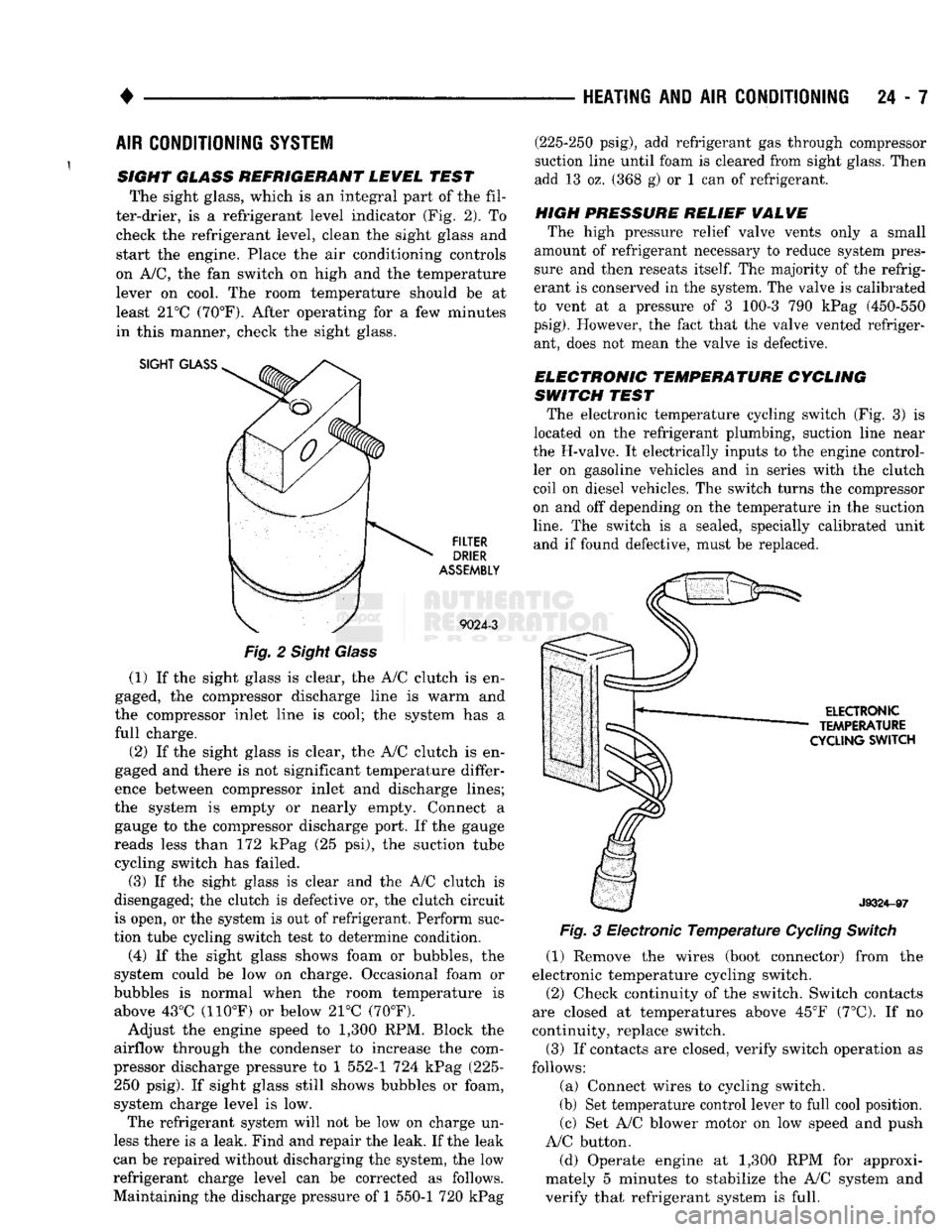
SIGHT GLASS REFRIGERANT LEWEL TEST The sight glass, which is an integral part of the fil
ter-drier, is a refrigerant level indicator (Fig. 2). To check the refrigerant level, clean the sight glass and
start the engine. Place the air conditioning controls
on A/C, the fan switch on high and the temperature lever on cool. The room temperature should be at
least 21°C (70°F). After operating for a few minutes
in this manner, check the sight glass.
SIGHT
GLASS
FILTER
DRIER
ASSEMBLY
9024-3
Fig.
2 Sight Glass
(1) If the sight glass is clear, the A/C clutch is en
gaged, the compressor discharge line is warm and
the compressor inlet line is cool; the system has a
full charge.
(2) If the sight glass is clear, the A/C clutch is en
gaged and there is not significant temperature differ
ence between compressor inlet and discharge lines;
the system is empty or nearly empty. Connect a gauge to the compressor discharge port. If the gauge
reads less than 172 kPag (25 psi), the suction tube cycling switch has failed.
(3) If the sight glass is clear and the A/C clutch is
disengaged; the clutch is defective or, the clutch circuit
is open, or the system is out of refrigerant. Perform suc
tion tube cycling switch test to determine condition.
(4) If the sight glass shows foam or bubbles, the
system could be low on charge. Occasional foam or
bubbles is normal when the room temperature is above 43°C (110°F) or below 21°C (70°F).
Adjust the engine speed to 1,300 RPM. Block the
airflow through the condenser to increase the com
pressor discharge pressure to 1 552-1 724 kPag (225- 250 psig). If sight glass still shows bubbles or foam,
system charge level is low. The refrigerant system will not be low on charge un
less there is a leak. Find and repair the leak. If the leak
can be repaired without discharging the system, the low
refrigerant charge level can be corrected as follows.
Maintaining the discharge pressure of 1 550-1 720 kPag (225-250 psig), add refrigerant gas through compressor
suction line until foam is cleared from sight glass. Then
add 13 oz. (368 g) or 1 can of refrigerant.
HIGH PRESSURE RELIEF
WALWE
The high pressure relief valve vents only a small
amount of refrigerant necessary to reduce system pres
sure and then reseats
itself.
The majority of the refrig
erant is conserved in the system. The valve is calibrated
to vent at a pressure of 3 100-3 790 kPag (450-550
psig).
However, the fact that the valve vented refriger ant, does not mean the valve is defective.
ELECTRONIC TEMPERATURE CYCLING
SWITCH TEST The electronic temperature cycling switch (Fig. 3) is
located on the refrigerant plumbing, suction line near
the H-valve. It electrically inputs to the engine control ler on gasoline vehicles and in series with the clutch
coil on diesel vehicles. The switch turns the compressor
on and off depending on the temperature in the suction
line.
The switch is a sealed, specially calibrated unit and if found defective, must be replaced.
ELECTRONIC
TEMPERATURE
CYCLING
SWITCH
J9324-97
Fig.
3 Electronic
Temperature
Cycling
Switch
(1) Remove the wires (boot connector) from the
electronic temperature cycling switch. (2) Check continuity of the switch. Switch contacts
are closed at temperatures above 45°F (7°C). If no
continuity, replace switch.
(3) If contacts are closed, verify switch operation as
follows:
(a) Connect wires to cycling switch.
(b) Set temperature control lever to full cool position. (c) Set A/C blower motor on low speed and push
A/C button.
(d) Operate engine at 1,300 RPM for approxi
mately 5 minutes to stabilize the A/C system and
verify that refrigerant system is full.