1993 DODGE TRUCK air suspension
[x] Cancel search: air suspensionPage 88 of 1502
•
FRONT
SUSPENSION
AND
AXLE
2 - 35
PINION
MATE SHAFT ADAPTERS
DRIFT
J9203-60
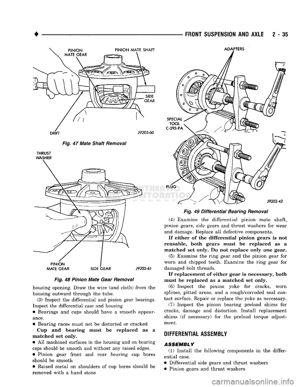
Fig.
47
Mate
Shaft
Removal
THRUST
WASHER
PINION
MATE GEAR SIDE GEAR
J9203-61
Fig.
48
Pinion
Mate
Gear
Removal
housing opening. Draw the wire (and cloth) from the
housing outward through the tube. (3) Inspect the differential and pinion gear bearings.
Inspect the differential case and housing.
• Bearings and cups should have a smooth appear
ance.
• Bearing races must not be distorted or cracked Cup and bearing must be replaced as a
matched set only. • All machined surfaces in the housing and on bearing
caps should be smooth and without any raised edges.
• Pinion gear front and rear bearing cup bores should be smooth
• Raised metal on shoulders of cup bores should be
removed with a hand stone
PLUG
SPECIAL
TOOL
C-293-PA
J9202-42
Fig.
49
Differential
Bearing
Removal
(4) Examine the differential pinion mate shaft,
pinion gears, side gears and thrust washers for wear and damage. Replace all defective components.
If either of the differential pinion gears is not
reusable, both gears must be replaced as a matched set only. Do not replace only one gear.
(5) Examine the ring gear and the pinion gear for
worn and chipped teeth. Examine the ring gear for damaged bolt threads.
If replacement of either gear is necessary, both
must be replaced as a matched set only.
(6) Inspect the pinion yoke for cracks, worn
splines, pitted areas, and a rough/corroded seal con
tact surface. Repair or replace the yoke as necessary.
(7) Inspect the pinion bearing preload shims for
cracks, damage and distortion. Install replacement shims (if necessary) for the preload torque adjust
ment.
DIFFERENTIAL
ASSEMBLY
ASSEMBLY (1) Install the following components in the differ
ential case.
• Differential side gears and thrust washers
• Pinion gears and thrust washers
Page 115 of 1502
2
- 82
FRONT SUSPENSION
AND
AXLE
•
SPECIAL
TOOL
DD-914-P
J9203-59
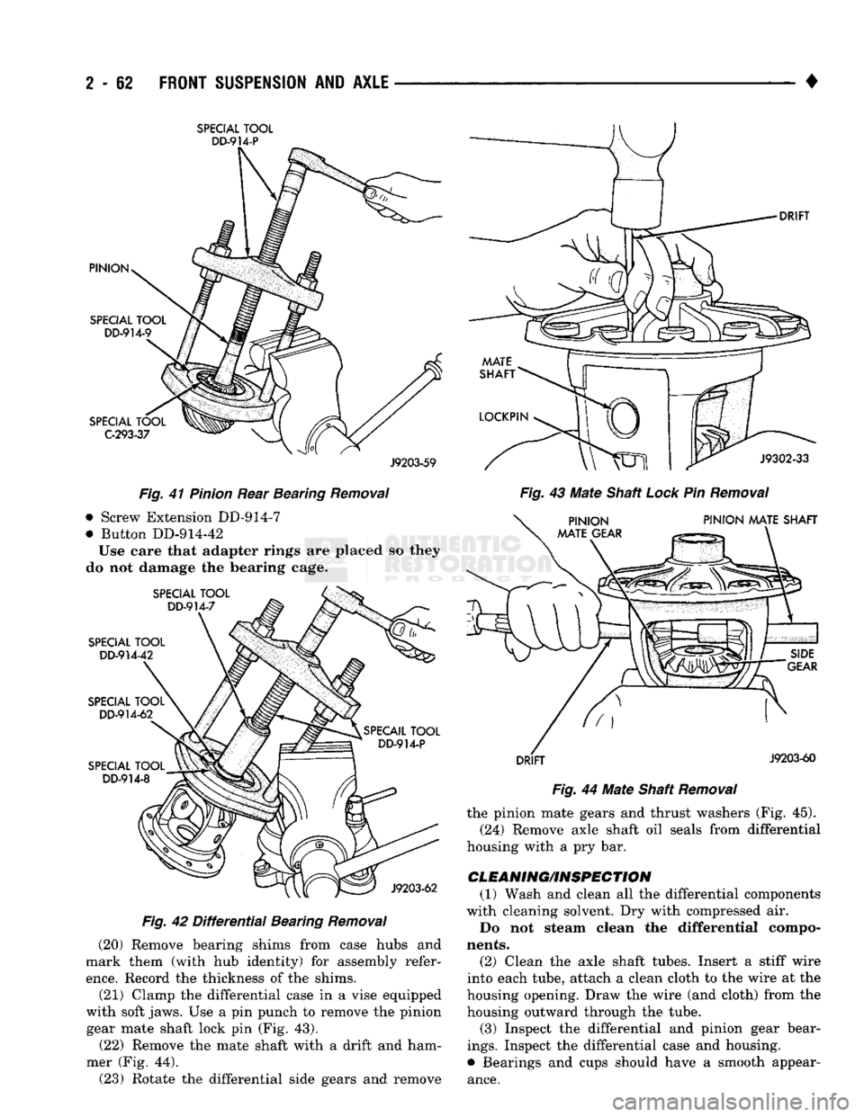
Fig.
41
Pinion
Rear Bearing
Removal
• Screw Extension DD-914-7
• Button DD-914-42
Use eare that adapter rings are placed so they
do not damage the bearing cage.
Fig.
42
Differential
Bearing
Removal
(20) Remove bearing shims from case hubs and
mark them (with hub identity) for assembly refer
ence.
Record the thickness of the shims.
(21) Clamp the differential case in a vise equipped
with soft jaws. Use a pin punch to remove the pinion gear mate shaft lock pin (Fig. 43).
(22) Remove the mate shaft with a drift and ham
mer (Fig. 44). (23) Rotate the differential side gears and remove
Fig.
43 Mate Shaft
Lock
Pin
Removal
Fig.
44 Mate Shaft
Removal
the pinion mate gears and thrust washers (Fig. 45).
(24) Remove axle shaft oil seals from differential
housing with a pry bar.
CLEANING/INSPECTION (1) Wash and clean all the differential components
with cleaning solvent. Dry with compressed air.
Do not steam clean the differential compo
nents.
(2) Clean the axle shaft tubes. Insert a stiff wire
into each tube, attach a clean cloth to the wire at the
housing opening. Draw the wire (and cloth) from the housing outward through the tube.
(3) Inspect the differential and pinion gear bear
ings.
Inspect the differential case and housing.
• Bearings and cups should have a smooth appear
ance.
Page 116 of 1502
•
FRONT SUSPENSION
AND
AXLE
2 - 63
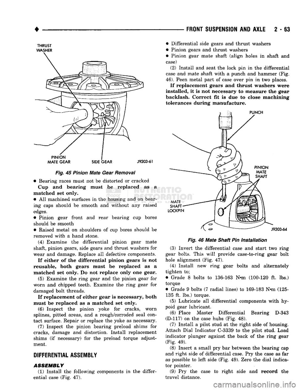
THRUST
WASHER
Fig.
45
Pinion
Mate
Gear
Removal
• Bearing races must not be distorted or cracked
Cup and bearing must be replaced as a
matched set only. • All machined surfaces in the housing and on bear
ing caps should be smooth and without any raised
edges.
• Pinion gear front and rear bearing cup bores should be smooth
• Raised metal on shoulders of cup bores should be
removed with a hand stone.
(4) Examine the differential pinion gear mate
shaft, pinion gears, side gears and thrust washers for
wear and damage. Replace all defective components.
If either of the differential pinion gears is not
reusable, both gears must be replaced as a
matched set only. Do not replace only one gear.
(5) Examine the ring gear and the pinion gear for
worn and chipped teeth. Examine the ring gear for damaged bolt threads.
If replacement of either gear is necessary, both
must be replaced as a matched set only. (6) Inspect the pinion yoke for cracks, worn
splines, pitted areas, and a rough/corroded seal con
tact surface. Repair or replace the yoke as necessary. (7) Inspect the pinion bearing preload shims for
cracks, damage and distortion. Install replacement shims (if necessary) for the preload torque adjust
ment.
DIFFERENTIAL
ASSEMBLY
ASSEMBLY
(1) Install the following components in the differ
ential case (Fig. 47). • Differential side gears and thrust washers
• Pinion gears and thrust washers
• Pinion gear mate shaft (align holes in shaft and
case) (2) Install and seat the lock pin in the differential
case and mate shaft with a punch and hammer (Fig.
46).
Peen metal part of case over pin in two places. If replacement gears and thrust washers were
installed, it is not necessary to measure the gear
backlash. Correct fit is due to close machining tolerances during manufacture.
Fig.
46
Mate
Shaft Pin
Installation
(3) Invert the differential case and start two ring
gear bolts. This will provide case-to-ring gear bolt
hole alignment (Fig. 47). (4) Install new ring gear bolts and alternately
tighten to;
• Grade 8 bolts to 136-163 N*m (100-120 ft. lbs.)
torque
• Grade 9 bolts (7 radial lines) to 169-183 N*m (125- 135 ft. lbs.) torque.
(5) Lubricate all differential components with hy
poid gear lubricant. (6) Place Master Differential Bearing D-343
(D-117) on the case hubs (Fig. 48). (7) Install a pilot stud at the right side of housing.
Attach Dial Indicator C-3339 to the pilot stud. Load indicator plunger against the back of the ring gear (Fig. 49).
(8) Insert a small pry bar between the bearing cap
and right side of differential case. Pry the case as far
as possible to left side (Fig. 49). Zero the dial indica
tor pointer.
(9) Pry the case to right side and record the
travel distance.
Page 128 of 1502
FRONT
SUSPENSION
AND
AXLE
2 - 75
SPECIFICATIONS
MODEL
60
FRONT
AXLE
Axle Type........
Semi-floating,
hypoid
Application
D-TRK Ring Gear
Diameter
9.75
in.
(24.76 cm)
Lubricants
MOPAR
Gear
Lubricant
or
equivalent
SAE
75W-90,
API
Grade
GL-5,
MIL-L-2105C
Locking
Hubs Manual
type
Lubricant Capacity
6.5
pts. (3.1L)
Axle Model Dana
M60F
Axle Ratio.........
3.54
Tol
4.10
4.56
Track... 65.7
in.
GAWR....................
4500
lbs.
TORQUE
SPECIFICATIONS
Differential
Bearing
Preload Shim 0.015
in.
0.38
mm
Differential
Side Gear-to-Case Clearance..
0.000-0.007
in.
0.00-0.18
mm
Ring
Gear Backlash 0.005-0,008
in.
0.12-0.20 mm
Drive Pinion Gearshaft Bearing Break-Away Preload Torque
Original
Bearings....
10-20
in. lbs. l-2N®m Replacement Bearings. 20-40
in.
lbs. 2-5 N®m
Drive Pinion Gear Depth Select shims Standard Setting.... 3.125
in.
79.37 mm
Side
Gear Clearance (max.) 0.006
in.
0.15
mm
Case
Runout (max.) 0.006
in.
0.15
mm
J9202-107
FRONT
SUSPENSION
COMPONENTS-
2WD
FRONT
SUSPENSION
COMPONENTS-
4WD
FRONT
SUSPENSION
COMPONENTS
%
WHEEL
DRIVE
FRONT
SUSPENSION
COMPONENTS
4
WHEEL
DRIVE
DESCRIPTION
TOROUE
Brake Rotor
Dust
Shield
Jounce Bumper to Bracket.... Lower
Suspension
Arm Pivot.
Lower Ball Stud
Nut
(11/16-18 Bolt)...............
Lower Ball Stud
Nut
(3/4-16 Bolt).....
Shock
Absorber Upper Nut..
Shock
Absorber Lower Bolt
..
Stabilizer Bar Retainer
Bolts
.
Stabilizer Bar Link Nut
Steering Arm to Knuckle 5/8-18 Bolt/Nut
.............
Steering Arm to Knuckle 3/4-16 Bolt/Nut . 20 N-m (180 in.
lbs.
....
41
N-m
(30
ft. lbs.
305
N-m (225
ft. lbs.
183
N-m (135
ft. lbs.
237 N-m (175
ft. lbs.
....
34
N-m
(25 ft.
lbs. .
23
N-m
(200
in. lbs.
.
23
N-m
(200
in. lbs.
. 11 N-m
(100
in. lbs.
Strut/Jounce Bumper to
Suspension
Arm Bolt/Nut.
Strut
Front
Nut Upper Ball Stud
Nut
290 N-m (215
ft. lbs.
330 N-m (225
ft.
lbs.
.. 129 N-m (95
ft.
lbs.
....
68
N-m
(50
ft.
lbs.
142
N-m
(105
ft.
lbs.
J9202-108
DESCRIPTION
TORQUE
Jounce Bumper to Bracket
....
Stabilizer Bar Retainer
Bolts..
Stabilizer Bar Link Nut
Shock
Absorber/Jounce Bracket to Frame
Shock
Absorber (Standard) Upper and Lower Nut
Shock
Absorber (Air Adjust) Upper Nut
Shock
Absorber (Air Adjust) Lower Nut
Spring
U-bolt/Stud Nuts (Model
44) ...
Spring
Front Pivot Nut (Model
44)
Spring
Rear Shackle
Nut
(Model
44)
Spring
U-bolt/Stud Nuts (Model
60)
Spring
Front
Pivot Nut (Model
60)
Spring
Rear Shackle Nut (Model
60)
...
41
N-m (30
ft.
lbs.)
23
N-m (200 in.
lbs.)
11
N-m
(100
in.
lbs.)
.. 101 N-m (75
ft.
lbs.)
.... 75 N-m (55
ft.
lbs.)
.... 75 N-m (55
ft.
lbs.)
271 N-m
(200
ft.
lbs.)
.. 115 N-m (85
ft.
lbs.)
135
N-m (100
ft.
lbs.)
.... 81 N-m
(60
ft.
lbs.)
..
129
N-m
(95
ft.
lbs.)
135
N-m (100
ft.
lbs.)
,.
108
N-m
(80
ft.
lbs.)
J9202-109
Page 132 of 1502
•
REAR
SUSPENSION
AND
AXLE
3 - 3
REAR SUSPENSION—2WD
and 4WD
VEHICLES
SPRING
AND
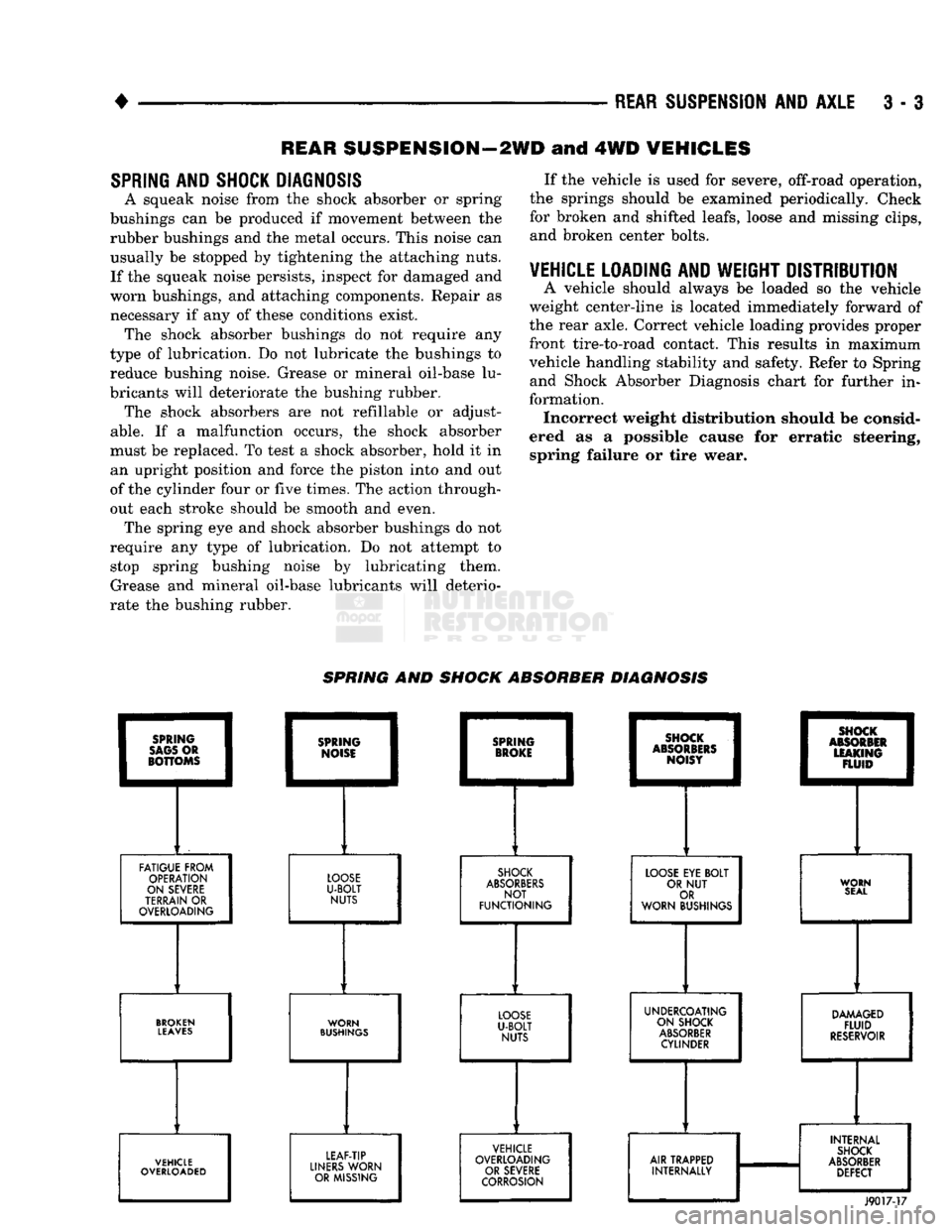
SHOCK DIAGNOSIS
A squeak noise from the shock absorber or spring
bushings can be produced if movement between the
rubber bushings and the metal occurs. This noise can usually be stopped by tightening the attaching nuts.
If the squeak noise persists, inspect for damaged and
worn bushings, and attaching components. Repair as
necessary if any of these conditions exist. The shock absorber bushings do not require any
type of lubrication. Do not lubricate the bushings to reduce bushing noise. Grease or mineral oil-base lu
bricants will deteriorate the bushing rubber. The shock absorbers are not reflllable or adjust
able.
If a malfunction occurs, the shock absorber
must be replaced. To test a shock absorber, hold it in an upright position and force the piston into and out
of the cylinder four or five times. The action through
out each stroke should be smooth and even. The spring eye and shock absorber bushings do not
require any type of lubrication. Do not attempt to stop spring bushing noise by lubricating them.
Grease and mineral oil-base lubricants will deterio
rate the bushing rubber. If the vehicle is used for severe, off-road operation,
the springs should be examined periodically. Check for broken and shifted leafs, loose and missing clips, and broken center bolts.
VEHICLE LOADING
AND
WEIGHT DISTRIBUTION
A vehicle should always be loaded so the vehicle
weight center-line is located immediately forward of
the rear axle. Correct vehicle loading provides proper
front tire-to-road contact. This results in maximum
vehicle handling stability and safety. Refer to Spring and Shock Absorber Diagnosis chart for further in
formation. Incorrect weight distribution should be consid
ered as a possible cause for erratic steering, spring failure or tire wear. SPRING AND SHOCK ABSORBER DIAGNOSIS
FATIGUE FROM
OPERATION
ON SEVERE
TERRAIN
OR
OVERLOADING
LOOSE
U-BOLT
NUTS
SHOCK
ABSORBERS
NOT
FUNCTIONING
LOOSE
EYE
BOLT
OR
NUT
OR
WORN BUSHINGS WORN
SEAL
BROKEN
LEAVES
WORN
BUSHINGS
UNDERCOATING
ON SHOCK
ABSORBER
CYLINDER
DAMAGED
FLUID
RESERVOIR
VEHICLE
OVERLOADED LEAF-TIP
LINERS
WORN OR MISSING VEHICLE
OVERLOADING OR SEVERE
CORROSION
AIR TRAPPED
INTERNALLY INTERNAL
SHOCK
ABSORBER
DEFECT
J9017-17
Page 135 of 1502
3
- 6
REAR SUSPENSION
AND
AXLE
•
NUT PIPE
SOCKET
WRENCH
(DRIVER)
FLAT
THREADED
WASHER
ROD
J8917-20
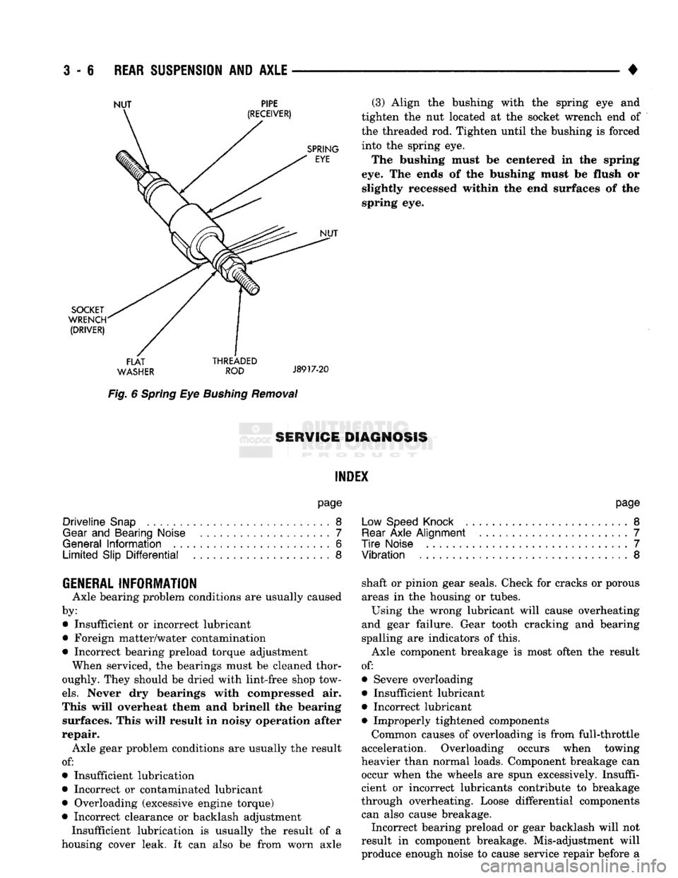
Fig.
6
Spring
Eye
Bushing
Removal
(3) Align
the
bushing with
the
spring
eye and
tighten
the nut
located
at the
socket wrench
end of
the threaded
rod.
Tighten until
the
bushing
is
forced into
the
spring
eye.
The bushing must
be
centered
in the
spring
eye.
The
ends
of the
bushing must
be
flush
or
slightly recessed within
the end
surfaces
of the
spring
eye.
8ERW1GE DIAGNOSIS
INDEX
page
Driveline
Snap
8
Gear
and
Bearing Noise
7
General
Information
6
Limited
Slip
Differential
8
page
Low Speed Knock
.........................
8
Rear
Axle
Alignment
.......................
7
Tire
Noise
7
Vibration
8
GENERAL INFORMATION
Axle bearing problem conditions
are
usually caused
by: • Insufficient
or
incorrect lubricant
• Foreign matter/water contamination
• Incorrect bearing preload torque adjustment When serviced,
the
bearings must
be
cleaned thor
oughly. They should
be
dried with lint-free shop tow
els.
Never
dry
bearings with compressed
air.
This will overheat them
and
brinell
the
bearing surfaces. This will result
in
noisy operation after
repair. Axle gear problem conditions
are
usually
the
result
of:
• Insufficient lubrication
• Incorrect
or
contaminated lubricant
• Overloading (excessive engine torque)
• Incorrect clearance
or
backlash adjustment Insufficient lubrication
is
usually
the
result
of a
housing cover leak.
It can
also
be
from worn axle shaft
or
pinion gear seals. Check
for
cracks
or
porous
areas
in the
housing
or
tubes.
Using
the
wrong lubricant will cause overheating
and gear failure. Gear tooth cracking
and
bearing
spalling
are
indicators
of
this.
Axle component breakage
is
most often
the
result
of:
• Severe overloading
• Insufficient lubricant
• Incorrect lubricant • Improperly tightened components
Common causes
of
overloading
is
from full-throttle
acceleration. Overloading occurs when towing
heavier than normal loads. Component breakage
can
occur when
the
wheels
are
spun excessively. Insuffi
cient
or
incorrect lubricants contribute
to
breakage
through overheating. Loose differential components can also cause breakage. Incorrect bearing preload
or
gear backlash will
not
result
in
component breakage. Mis-adjustment will
produce enough noise
to
cause service repair before
a
Page 137 of 1502
3
- 8
REAR SUSPENSION
AND
AXLE
• level. Where axle bearing damage is slight, the noise
is usually not noticeable at speeds above 30 mph.
LOW SPEED KNOCK
Low speed knock is generally caused by a worn
U-joint or by worn side-gear thrust washers. A worn
pinion gear shaft bore will also cause low speed knock.
VIBRATION
Vibration at the rear of the vehicle is usually
caused by a:
• Damaged drive shaft
• Missing drive shaft balance weight
• Worn, out-of-balance wheel and tires
• Loose wheel lug nuts
• Worn U-joint • Loose spring U-bolts
• Loose/broken rear springs or shackles
• Damaged axle shaft bearings
• Loose pinion gear nut
• Excessive pinion yoke run out
• Bent axle shaft Check for loose or damaged front-end components
or engine/transmission mounts. These components
can contribute to what appears to be a rear-end vi
bration. Do not overlook engine accessories, brackets and drive belts. All driveline components should be examined be
fore starting any repair. Refer to Group 22, Wheels and Tires for additional
information.
DRIVELINE SNAP
A snap or clunk noise when the vehicle is shifted
into gear (or the clutch engaged), can be caused by: • High engine idle speed
• Loose engine/transmission/transfer case mounts
9
Worn U-joints
• Loose spring shackles or U-bolts
• Loose pinion gear nut and yoke
• Excessive ring gear backlash
• Excessive differential side gear-to-case clearance A worn bushing in the transmission extension
housing can also cause noise. The source of a snap or a clunk noise can be deter
mined with the assistance of a helper. Raise the ve
hicle on a hoist with the wheels free to rotate. Instruct the helper to shift the transmission into gear. Listen for the noise, a mechanics stethoscope is
helpful in isolating the source of a noise.
LIMITED
SLIP DIFFERENTIAL
Under normal traction conditions, engine torque is
divided evenly. With low-traction surfaces, engine
torque is transferred to the wheel with the most tire
traction. When diagnosing a limited-slip differential
problem condition, the wheel with the least traction can continue spinning. The most common problem is a chatter noise when
turning corners. Check for incorrect or contaminated lubricant. Replace the gear lubricant if necessary.
• With Sure-Grip differentials add a container of
MOPAR® Hypoid Gear Additive This will correct the condition in most instances. If
the chatter persists, clutch damage could have oc curred. After changing the lubricant, drive the vehicle and
make 10 to 12 slow, figure-eight turns. This maneu
ver will pump lubricant through the clutches.
Page 138 of 1502
REAR
SUSPENSION
AND
AXLE
3 - 9
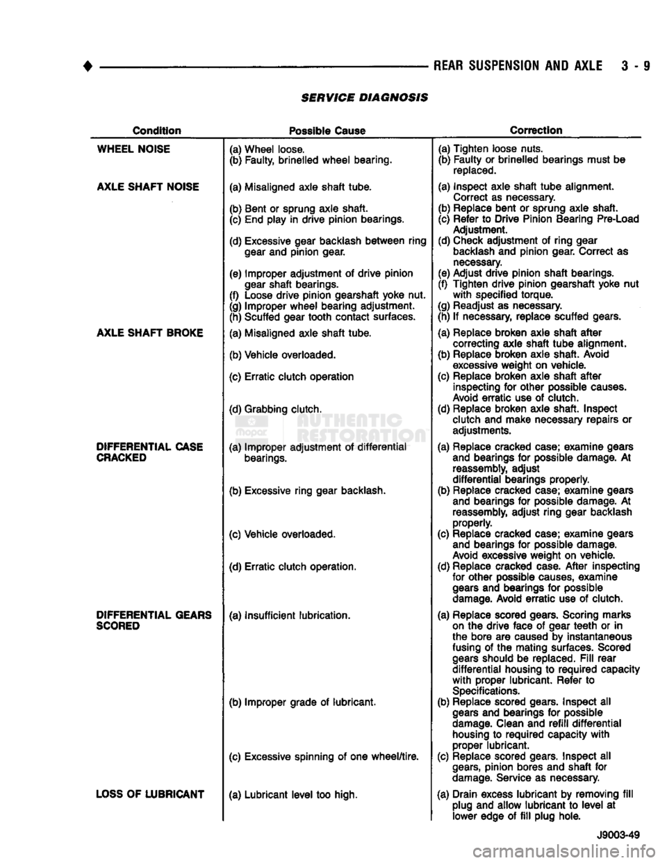
SERVICE DIAGNOSIS
Condition
Possible
Cause
Correction
WHEEL
NOISE
AXLE
SHAFT
NOISE
AXLE
SHAFT
BROKE
DIFFERENTIAL
CASE
CRACKED
DIFFERENTIAL
GEARS
SCORED
LOSS
OF
LUBRICANT
(a) Wheel loose.
(b) Faulty, brinelled
wheel
bearing.
(a) Misaligned axle shaft tube.
(b) Bent or sprung axle shaft. (c) End play in drive pinion bearings.
(d) Excessive gear backlash
between
ring
gear
and pinion gear.
(e) Improper adjustment of drive pinion
gear
shaft bearings.
(f) Loose drive pinion gearshaft yoke nut.
(g) Improper
wheel
bearing adjustment. (h) Scuffed gear tooth contact surfaces.
(a) Misaligned axle shaft tube.
(b) Vehicle overloaded.
(c) Erratic clutch operation
(d) Grabbing clutch.
(a) Improper adjustment of
differential
bearings.
(b) Excessive ring gear backlash.
(c) Vehicle overloaded. (d) Erratic clutch operation.
(a) Insufficient lubrication.
(b) Improper grade of lubricant.
(c) Excessive spinning of one
wheel/tire.
(a) Lubricant
level
too high. (a) Tighten loose nuts.
(b) Faulty or brinelled bearings must be
replaced.
(a) Inspect axle shaft
tube
alignment. Correct as necessary.
(b) Replace bent or sprung axle shaft.
(c) Refer to Drive Pinion Bearing Pre-Load Adjustment.
(d) Check adjustment of ring gear
backlash
and pinion gear. Correct as
necessary.
(e) Adjust drive pinion shaft bearings.
(f) Tighten drive pinion gearshaft yoke nut
with
specified torque.
(g) Readjust as necessary.
(h) If necessary, replace scuffed gears.
(a) Replace broken axle shaft
after
correcting axle shaft
tube
alignment.
(b) Replace broken axle shaft. Avoid
excessive
weight on vehicle.
(c) Replace broken axle shaft
after
inspecting for other possible
causes.
Avoid
erratic
use of clutch.
(d) Replace broken axle shaft. Inspect clutch and make necessary repairs or adjustments.
(a) Replace cracked case; examine gears and bearings for possible damage. At
reassembly,
adjust
differential
bearings properly.
(b) Replace cracked case; examine gears and bearings for possible damage. At
reassembly,
adjust ring gear backlash properly.
(c) Replace cracked case; examine gears and bearings for possible damage.
Avoid
excessive weight on vehicle.
(d) Replace cracked case.
After
inspecting for other possible
causes,
examine
gears
and bearings for possible
damage.
Avoid
erratic
use of clutch.
(a) Replace scored gears. Scoring marks
on
the drive face of gear
teeth
or in
the bore are caused by instantaneous
fusing
of the mating surfaces. Scored
gears
should be replaced.
Fill
rear
differential
housing to
required
capacity
with
proper lubricant. Refer to
Specifications.
(b) Replace scored gears. Inspect all
gears
and bearings for possible
damage.
Clean and
refill
differential
housing
to
required
capacity
with
proper lubricant.
(c) Replace scored gears. Inspect all
gears,
pinion bores and shaft for
damage.
Service as necessary.
(a) Drain excess lubricant by removing
fill
plug and allow lubricant to
level
at lower edge of
fill
plug hole.
J9003-49