1993 DODGE TRUCK check engine
[x] Cancel search: check enginePage 924 of 1502
•
FUEL
SYSTEM
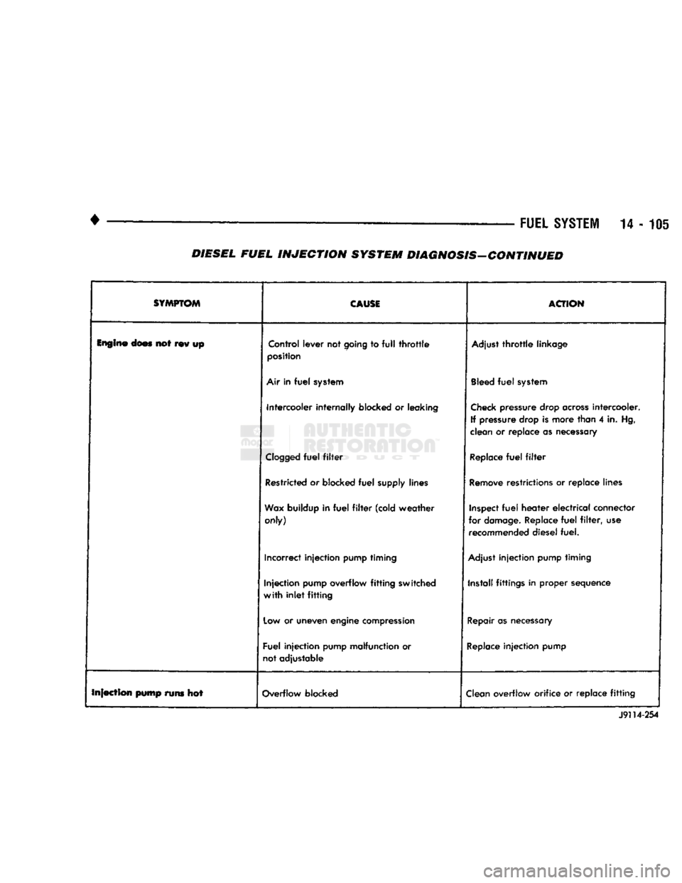
14-105 DIESEL FUEL INJECTION SYSTEM DIAGNOSIS-CONTINUED
SYMPTOM
CAUSE
ACTION
Engine
does not rev up Control lever not
going
to
full
throttle
position
Adjust
throttle
linkage
Air
in
fuel
system
Bleed
fuel
system
Intercooler internally blocked or leaking
Check
pressure drop
across
intercooler.
If pressure drop is more than 4 in. Hg,
clean or replace as necessary
Clogged
fuel
filter
Replace
fuel
filter
Restricted or blocked
fuel
supply lines
Remove
restrictions or replace lines
Wax
buildup in
fuel
filter
(cold weather only)
Inspect
fuel
heater
electrical
connector
for
damage.
Replace
fuel
filter,
use recommended diesel fuel.
Incorrect injection pump timing
Adjust
injection pump timing
Injection pump overflow
fitting
switched
with
inlet
fitting
Install fittings in proper sequence
Low
or uneven engine
compression
Repair
as
necessary
Fuel injection pump malfunction or
not adjustable
Replace
injection pump
Infection pump runs hot Overflow blocked
Clean
overflow orifice or replace
fitting
J9114-254
Page 927 of 1502
(10) Install air intake heater (with new gasket) in
reverse order of removal.
AIR
INTAKE
HE
A TER
RELA YS
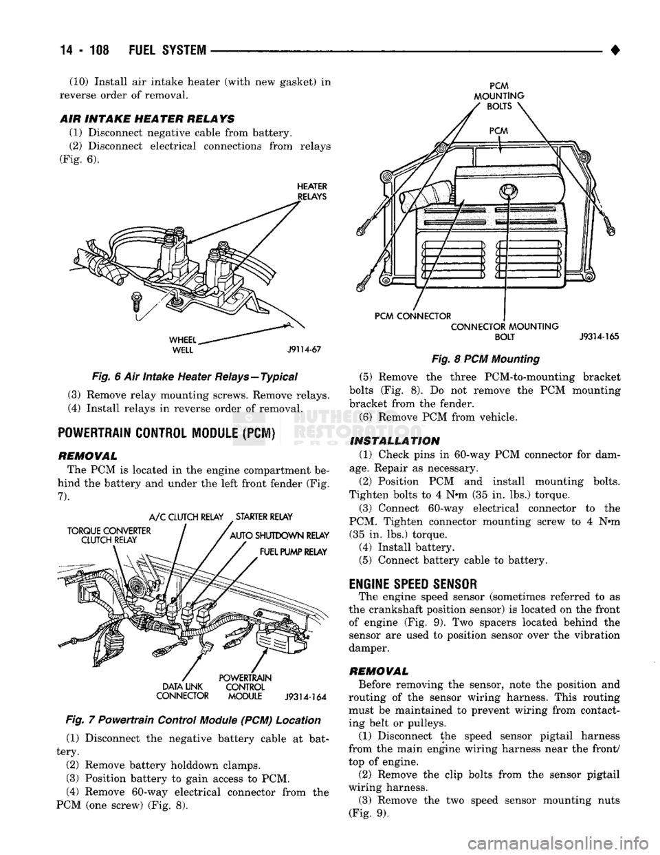
(1) Disconnect negative cable from battery.
(2) Disconnect electrical connections from relays
(Fig. 6).
HEATER
RELAYS
WHEEL..
WELL
J9114-67
Fig. 6 Air intake Heater Relays—Typical (3) Remove relay mounting screws. Remove relays.
(4) Install relays in reverse order of removal.
POWERTRAIN CONTROL MODULE
(PCI)
REMOWAL The PCM is located in the engine compartment be
hind the battery and under the left front fender (Fig.
7).
TORQUE CONVERTER
CLUTCH RELAY A/C CLUTCH RELAY STARTER RELAY
AUTO SHUTDOWN RELAY FUEL PUMP RELAY DATA LINK
CONNECTOR POWERTRAIN
CONTROL
MODULE
J9314-164
Fig. 7 Powertrain Control
Module
(PCM) Location (1) Disconnect the negative battery cable at bat
tery.
(2) Remove battery holddown clamps.
(3) Position battery to gain access to PCM,
(4) Remove 60-way electrical connector from the
PCM (one screw) (Fig. 8).
PCM
MOUNTING BOLTS
PCM CONNECTOR CONNECTOR MOUNTING
BOLT
J9314-165
Fig. 8 PCM Mounting (5) Remove the three PCM-to-mounting bracket
bolts (Fig. 8). Do not remove the PCM mounting
bracket from the fender.
(6) Remove PCM from vehicle.
INSTALLATION (1) Check pins in 60-way PCM connector for dam
age.
Repair as necessary.
(2) Position PCM and install mounting bolts.
Tighten bolts to 4 N*m (35 in. lbs.) torque.
(3) Connect 60-way electrical connector to the
PCM. Tighten connector mounting screw to 4 N#m (35 in. lbs.) torque. (4) Install battery. (5) Connect battery cable to battery.
ENGINE
SPEED SENSOR
The engine speed sensor (sometimes referred to as
the crankshaft position sensor) is located on the front of engine (Fig. 9). Two spacers located behind the
sensor are used to position sensor over the vibration
damper.
REMOWAL Before removing the sensor, note the position and
routing of the sensor wiring harness. This routing must be maintained to prevent wiring from contact
ing belt or pulleys.
(1) Disconnect the speed sensor pigtail harness
from the main engine wiring harness near the front/
top of engine.
(2) Remove the clip bolts from the sensor pigtail
wiring harness. (3) Remove the two speed sensor mounting nuts
(Fig. 9).
Page 931 of 1502
14 - 112
FUEL
SYSTEM
J9114-57
Fig.
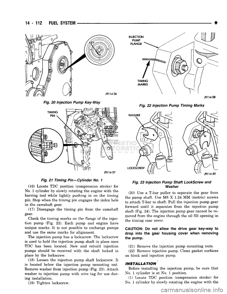
21 Timing Pin—Cylinder No. 1 (16) Locate TDC position (compression stroke) for
No.
1 cylinder by slowly rotating the engine with the
barring tool while lightly pushing in on the timing
pin. Stop when the timing pin engages the index hole in the camshaft gear.
(17) Disengage the timing pin from the camshaft
gear.
Check the timing marks on the flange of the injec
tion pump (Fig. 22). Each pump and engine have unique marks. It is not possible to exchange pumps and use the same marks for alignment.
The injection pump has a lockscrew. The lockscrew
is used to hold the injection pump shaft in place once
TDC has been located. New and rebuilt injection
pumps should be received with the shaft locked in
place by the lockscrew.
(18) Loosen the injection pump shaft lockscrew. It
is located below the injection pump mounting nut.
Remove washer from injection pump (Fig. 23). Attach
washer to injection pump with wire tag for use dur ing installation. (19) Tighten lockscrew.
J9114-58
Fig.
22 Injection
Pump
Timing Marks
Fig.
23 Injection
Pump
Shaft
LockScrew
and
Washer
(20) Use a T-bar puller to separate the gear from
the pump shaft. Use M8 X 1.24 MM (metric) screws
to attach T-bar to shaft. Pull the injection pump gear forward until it separates from the injection pump shaft (Fig. 24). The injection pump gear cannot be re
moved from the engine through the oil fill opening in
the timing case cover.
CAUTION:
Do not allow the drive
gear
key-way to
drop
into the
gear
housing
cover
when removing
the
pump.
(21) Remove the injection pump mounting nuts.
(22) Remove injection pump. Clean gasket surfaces
on block and injection pump.
INSTALLATION Before installing the injection pump, be sure that
No.
1 cylinder is at No. 1 position. (1) Locate TDC position (compression stroke) for
No.
1 cylinder by slowly rotating the engine with the
Page 936 of 1502
•
FUEL
SYSTEM
14-117
(5)
Bleed air from the fuel system. Refer to High
Pressure Fuel Lines in the Air Bleeding portion of
this section.
INJECTION
TIMING
If incorrect injection timing is suspected, injection
pump-to-engine timing or injection pump timing may
be the cause. Check injection pump timing before checking injection pump-to-engine timing.
INJECTION
PUMP
TIMING
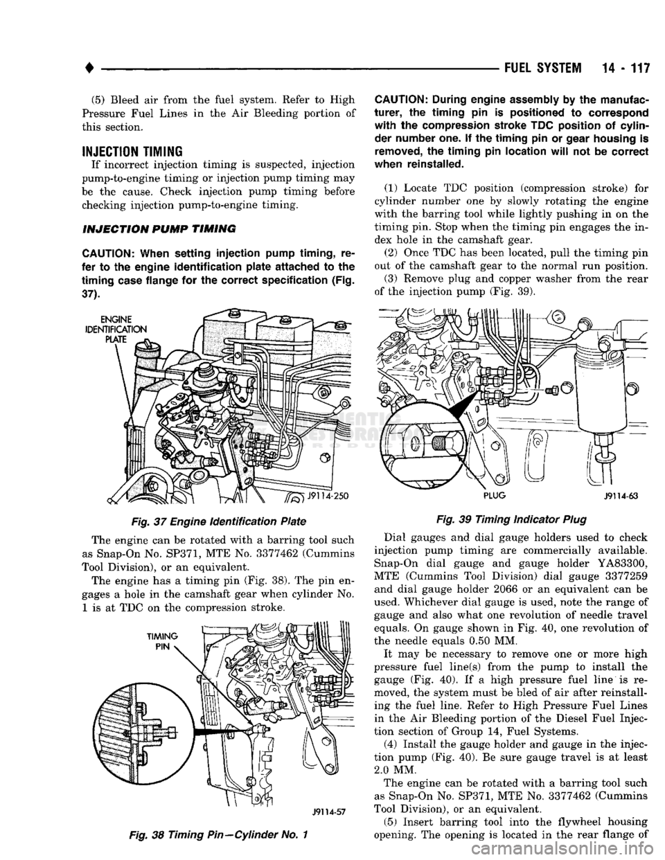
CAUTION;
When
setting
injection
pump
timing,
re
fer to the engine
identification
plate
attached
to the
timing
case
flange for the
correct
specification
(Fig.
37). Fig. 37
Engine
identification Plate
The engine can be rotated with a barring tool such
as Snap-On No.
SP371,
MTE No. 3377462 (Cummins
Tool Division), or an equivalent.
The engine has a timing pin (Fig. 38). The pin en
gages a hole in the camshaft gear when cylinder No.
1
is at TDC on the compression stroke.
J9114-57
Fig. 38
Timing
Pin—Cylinder
No. 1
CAUTION:
During engine
assembly
by the manufac
turer,
the
timing
pin is positioned to correspond
with
the compression stroke TDC position of cylinder number one. If the
timing
pin or
gear
housing
is
removed,
the
timing
pin
location
will
not be
correct
when reinstalled.
(1)
Locate TDC position (compression stroke) for
cylinder number one by slowly rotating the engine
with the barring tool while lightly pushing in on the
timing pin. Stop when the timing pin engages the in dex hole in the camshaft gear. (2) Once TDC has been located, pull the timing pin
out of the camshaft gear to the normal run position.
(3) Remove plug and copper washer from the rear
of the injection pump (Fig. 39).
PLUG
J9114-63
Fig. 39
Timing Indicator
Plug
Dial gauges and dial gauge holders used to check
injection pump timing are commercially available. Snap-On dial gauge and gauge holder YA83300,
MTE (Cummins Tool Division) dial gauge 3377259 and dial gauge holder 2066 or an equivalent can be
used. Whichever dial gauge is used, note the range of
gauge and also what one revolution of needle travel
equals. On gauge shown in Fig. 40, one revolution of
the needle equals 0.50 MM.
It may be necessary to remove one or more high
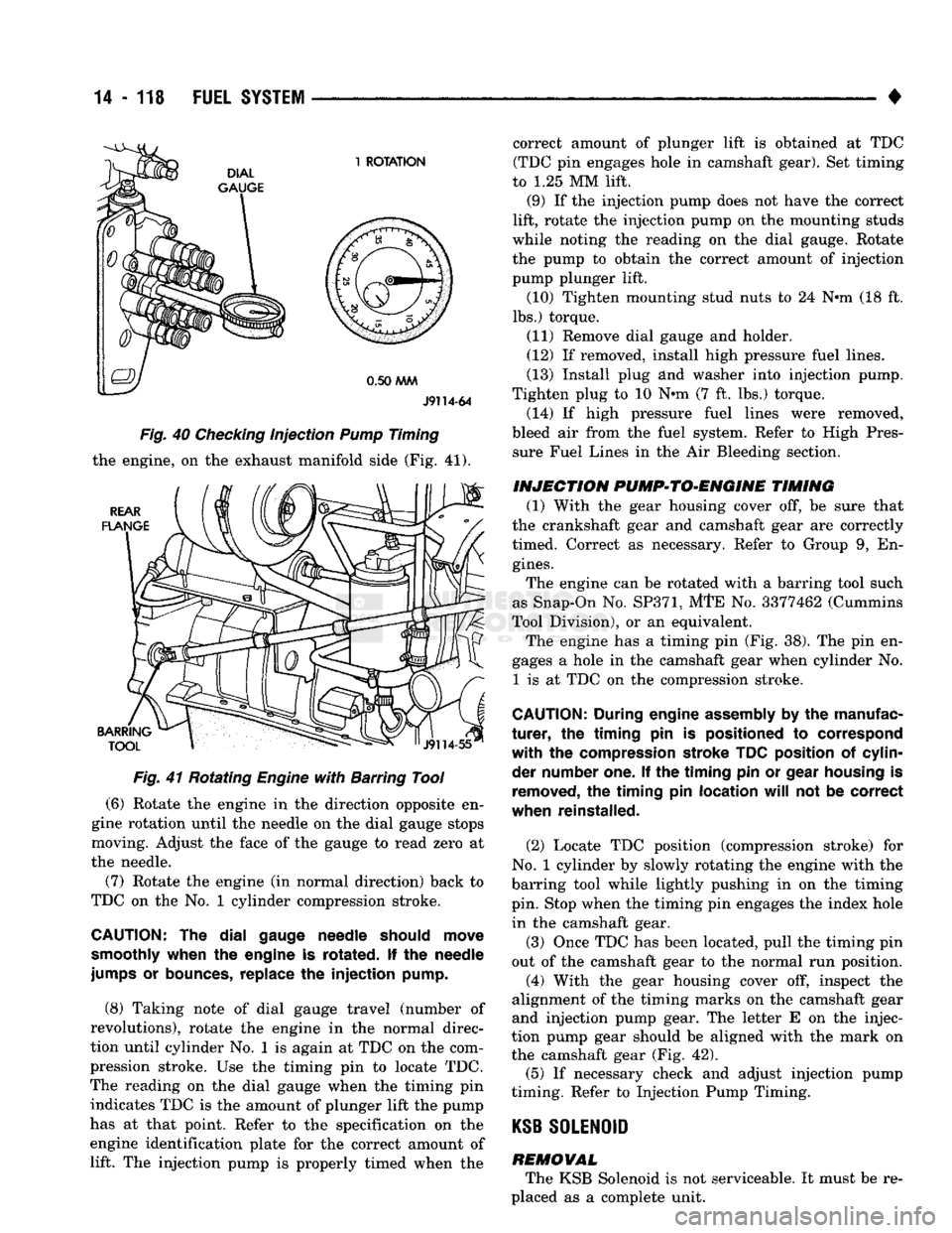
pressure fuel line(s) from the pump to install the gauge (Fig. 40). If a high pressure fuel line is re
moved, the system must be bled of air after reinstall ing the fuel line. Refer to High Pressure Fuel Lines
in the Air Bleeding portion of the Diesel Fuel Injec
tion section of Group 14, Fuel Systems.
(4) Install the gauge holder and gauge in the injec
tion pump (Fig. 40). Be sure gauge travel is at least 2.0 MM. The engine can be rotated with a barring tool such
as Snap-On No. SP371, MTE No. 3377462 (Cummins
Tool Division), or an equivalent.
(5) Insert barring tool into the flywheel housing
opening. The opening is located in the rear flange of
Page 937 of 1502
14
- 118
FUEL
SYSTEM
•
J9114-64
Fig. 40 Checking injection Pump Timing
the engine, on the exhaust manifold side (Fig.
41).
Fig. 41 Rotating Engine with Barring Tool
(6)
Rotate the engine in the direction opposite en
gine rotation until the needle on the dial gauge stops
moving. Adjust the face of the gauge to read zero at
the needle.
(7) Rotate the engine (in normal direction) back to
TDC on the No. 1 cylinder compression stroke.
CAUTION:
The dial
gauge needle should move
smoothly when
the
engine
is
rotated.
If the
needle
jumps
or
bounces, replace
the injection
pump.
(8)
Taking note of dial gauge travel (number of
revolutions), rotate the engine in the normal direc
tion until cylinder No. 1 is again at TDC on the com
pression stroke. Use the timing pin to locate TDC.
The reading on the dial gauge when the timing pin indicates TDC is the amount of plunger lift the pump
has at that point. Refer to the specification on the
engine identification plate for the correct amount of lift. The injection pump is properly timed when the correct amount of plunger lift is obtained at TDC
(TDC pin engages hole in camshaft gear). Set timing
to
1.25
MM lift.
(9)
If the injection pump does not have the correct
lift, rotate the injection pump on the mounting studs
while noting the reading on the dial gauge. Rotate
the pump to obtain the correct amount of injection
pump plunger lift.
(10)
Tighten mounting stud nuts to
24
N*m
(18
ft.
lbs.) torque.
(11)
Remove dial gauge and holder.
(12)
If removed, install high pressure fuel lines.
(13)
Install plug tod washer into injection pump.
Tighten plug to
10
Nnn
(7
ft. lbs.) torque.
(14)
If high pressure fuel lines were removed,
bleed air from the fuel system. Refer to High Pres sure Fuel Lines in the Air Bleeding section.
INJECTION PVMP*>TO*ENGINE TIMING
(1)
With the gear housing cover off, be sure that
the crankshaft gear and camshaft gear are correctly
timed. Correct as necessary. Refer to Group
9,
En
gines.
The engine can be rotated with a barring tool such
as Snap-On No.
SP371,
MTE No.
3377462
(Cummins
Tool Division), or an equivalent. The engine has a timing pin (Fig.
38).
The pin en
gages a hole in the camshaft gear when cylinder No.
1
is at TDC on the compression stroke.
CAUTION;
During engine assembly
by the
manufac
turer, the timing pin is
positioned
to
correspond
with the
compression stroke TDC position
of
cylin
der number one.
If the timing pin or
gear housing
is
removed,
the timing pin
location
will
not be
correct
when reinstalled.
(2)
Locate TDC position (compression stroke) for
No.
1 cylinder by slowly rotating the engine with the
barring tool while lightly pushing in on the timing
pin. Stop when the timing pin engages the index hole in the camshaft gear.
(3)
Once TDC has been located, pull the timing pin
out of the camshaft gear to the normal run position.
(4)
With the gear housing cover off, inspect the
alignment of the timing marks on the camshaft gear
and injection pump gear. The letter E on the injec
tion pump gear should be aligned with the mark on
the camshaft gear (Fig.
42).
(5)
If necessary check and adjust injection pump
timing. Refer to Injection Pump Timing.
KSB
SOLENOID
REMOVAL The KSB Solenoid is not serviceable. It must be re
placed as a complete unit.
Page 940 of 1502
•
FUEL
SYSTEM
14 - 121
Fig.
49
Throttle
Position
Sensor
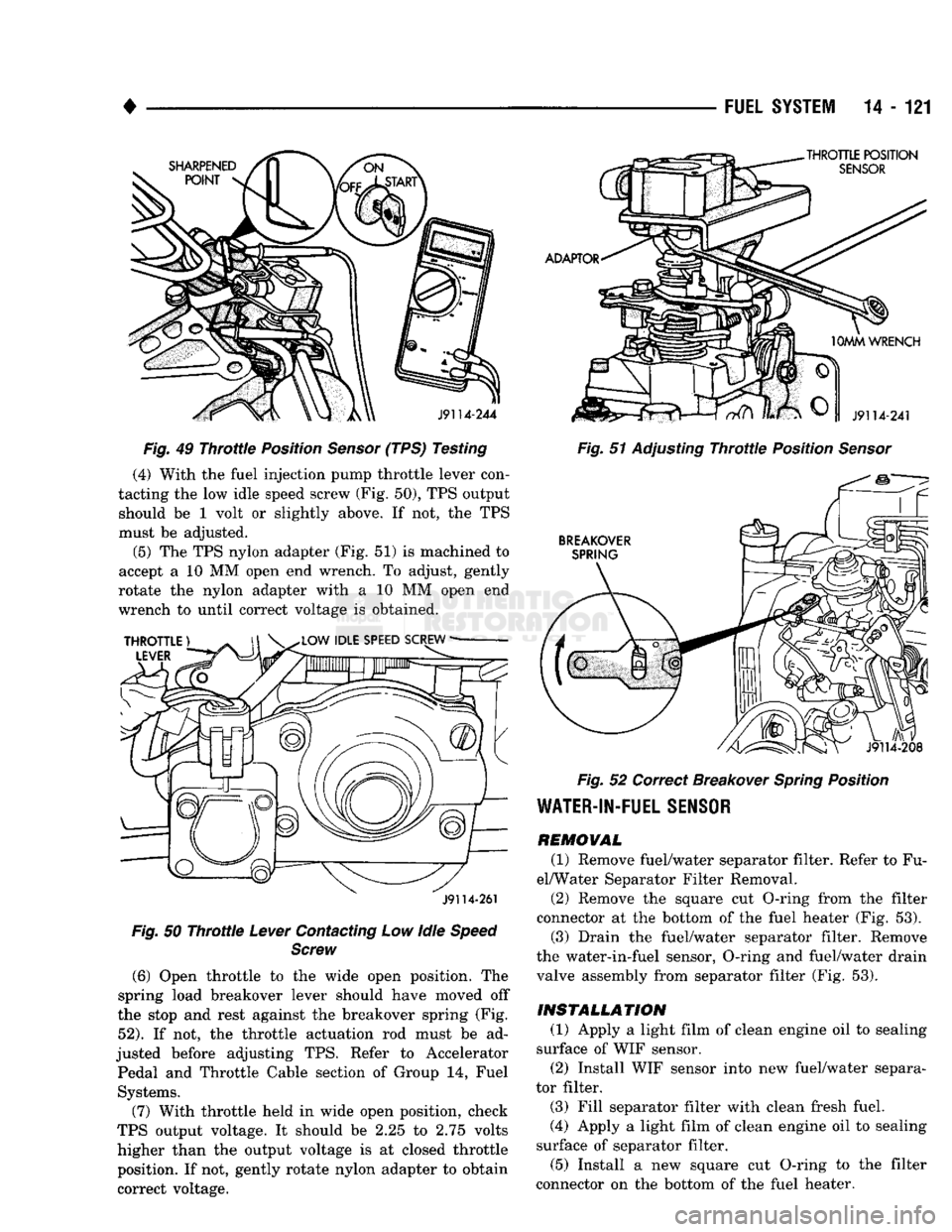
(TPS) Testing (4) With the fuel injection pump throttle lever con
tacting the low idle speed screw (Fig. 50), TPS output should be 1 volt or slightly above. If not, the TPS
must be adjusted.
(5) The TPS nylon adapter (Fig. 51) is machined to
accept a 10 MM open end wrench. To adjust, gently
rotate the nylon adapter with a 10 MM open end
wrench to until correct voltage is obtained.
J9114-261
Fig.
50
Throttle
Lever
Contacting Low Idle
Speed Screw
(6)
Open throttle to the wide open position. The
spring load breakover lever should have moved off
the stop and rest against the breakover spring (Fig.
52).
If not, the throttle actuation rod must be ad
justed before adjusting TPS. Refer to Accelerator Pedal and Throttle Cable section of Group 14, Fuel Systems.
(7) With throttle held in wide open position, check
TPS output voltage. It should be 2.25 to 2.75 volts
higher than the output voltage is at closed throttle position. If not, gently rotate nylon adapter to obtain
correct voltage.
Fig.
51 Adjusting
Throttle
Position
Sensor
Fig.
52 Correct Breakover
Spring
Position
WATER-IN-FUEL
SENSOR
REMOVAL
(1) Remove fuel/water separator filter. Refer to Fu
el/Water Separator Filter Removal.
(2) Remove the square cut O-ring from the filter
connector at the bottom of the fuel heater (Fig. 53). (3) Drain the fuel/water separator filter. Remove
the water-in-fuel sensor, O-ring and fuel/water drain
valve assembly from separator filter (Fig. 53).
INSTALLATION
(1) Apply a light film of clean engine oil to sealing
surface of WIF sensor. (2) Install WIF sensor into new fuel/water separa
tor filter.
(3) Fill separator filter with clean fresh fuel.
(4) Apply a light film of clean engine oil to sealing
surface of separator filter.
(5) Install a new square cut O-ring to the filter
connector on the bottom of the fuel heater.
Page 948 of 1502
•
PROPELLER SHAFTS
16 - 3
SERVICE
DIAGNOSIS/PROCEDURES
INDEX
page page
Precautions . 3 Universal
Joint
Angle Measurement ............ 4
Runout
4
Vibration
3
Unbalance
3
PRECAUTIONS
Propeller shafts are balanced by the manufacturer
to prevent vibration. Before undercoating a vehicle, the propeller shaft and the U-joints should be covered. This will prevent the undercoating from caus
ing an unbalanced condition and vibration. Use exact replacement hardware for attaching the
propeller shafts. Exact replacement will ensure safe operation. The specified torque must always be ap
plied when tightening the fasteners.
VIBRATION
Tires that are out-of-round or wheels that are un
balanced will cause a low frequency vibration. Refer to Group 22, Tires And Wheels for service informa
tion. Brake drums that are unbalanced will cause harsh,
low frequency vibration. Refer to Group 5, Brakes for
service information. Driveline vibration can also result from loose or
damaged engine mounts. Refer to Group 21, Trans
missions for additional information. Propeller shaft vibration will increase as the vehi
cle speed is increased. A vibration that occurs within a specific speed range is not caused by propeller
shaft unbalance. Defective U-joints or an incorrect
propeller shaft angle are usually the cause.
UNBALANCE
If propeller shaft unbalance is suspected, it can be
verified with the following procedure. Removing and re-indexing the propeller shaft
180° may eliminate some vibrations. (1) Raise and support the vehicle.
(2) Clean all foreign material from propeller shaft
and U-joints. (3) Inspect propeller shaft for missing balance
weights, broken welds, and bent areas. If the pro
peller shaft is bent, it must be replaced. (4) Ensure the U-joints are not worn and are prop
erly installed. (5) Check the U-joint clamp screws torque.
(6) Remove wheels and tires. Install wheel lug
nuts to retain brake drums in place. (7) Mark and number the shaft at four positions
90° apart, six inches from the yoke weld end.
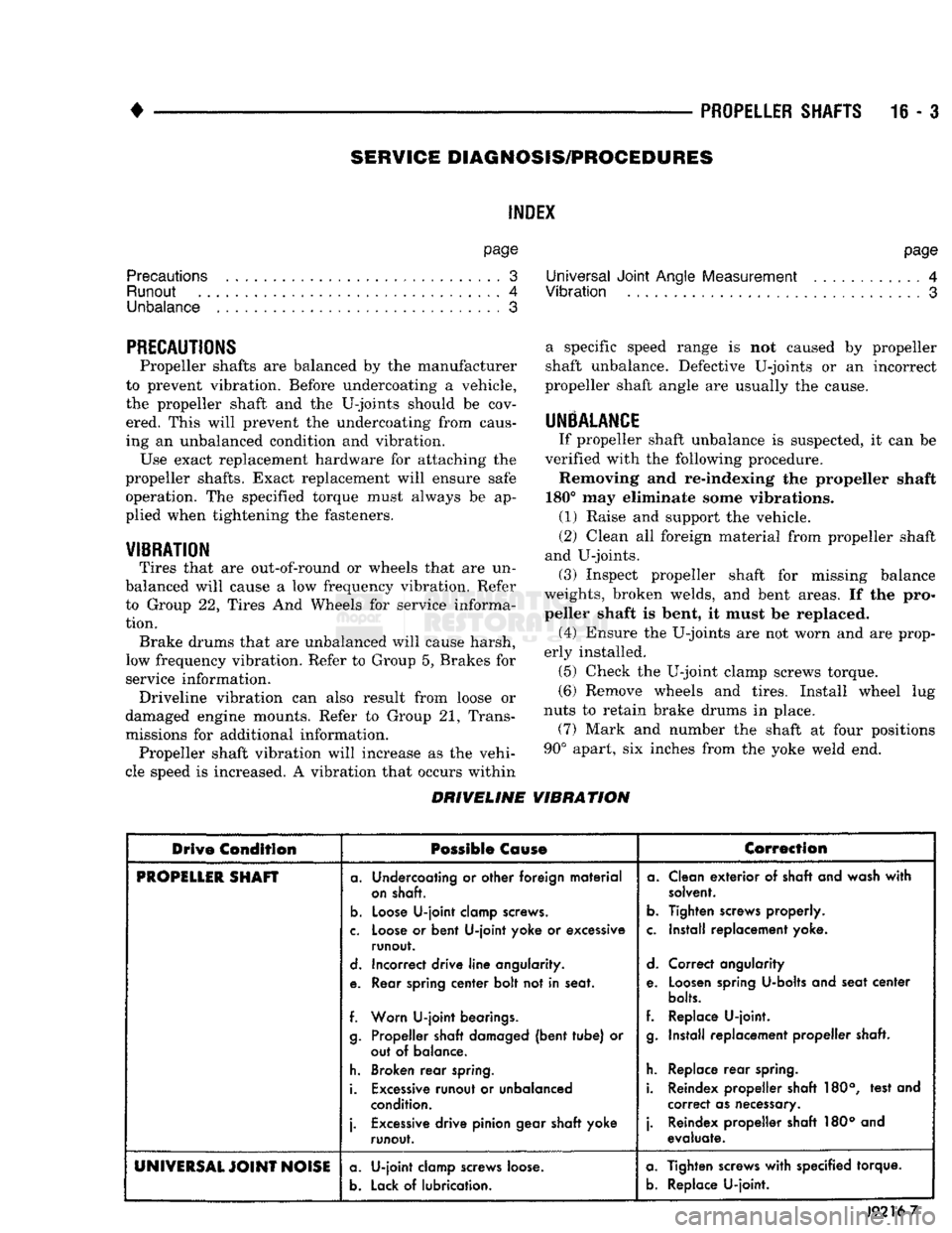
DRIVELINE VIBRATION
Drive
Condition
Possible Cause
Correction
PROPiLLlR
SHAFT
a. Undercoating or other foreign material
on shaft.
b.
Loose U-joint clamp screws.
c. Loose or bent U-joint yoke or excessive runout.
d. Incorrect drive line angularity.
e. Rear spring center bolt not in seat.
f. Worn U-joint bearings. g. Propeller shaft damaged (bent tube) or out of balance.
h. Broken rear spring.
i. Excessive runout or unbalanced condition.
j.
Excessive drive pinion gear shaft yoke runout. a. Clean exterior of shaft and wash with
solvent.
b.
Tighten screws properly.
c. Install replacement yoke.
d. Correct angularity
e. Loosen spring U-bolts and seat center
bolts.
f. Replace U-joint. g. Install replacement propeller shaft.
h. Replace rear spring.
i. Reindex propeller shaft 180°, test and correct as necessary.
j.
Reindex propeller shaft 180° and evaluate.
UNIVERSAL
JOINT
NOISE a. U-joint clamp screws loose.
b.
Lack of lubrication. a. Tighten screws with specified torque.
b.
Replace U-joint.
J9216-7
Page 949 of 1502
16-4 PROPELLER SHAFTS
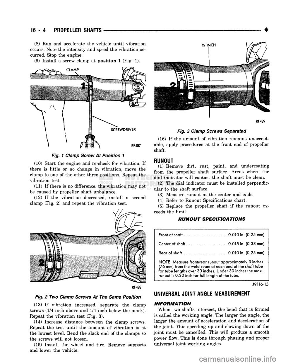
• (8) Run and accelerate the vehicle until vibration
occurs. Note the intensity and speed the vibration oc
curred. Stop the engine. (9) Install a screw clamp at position I (Fig. 1).
Fig.
1 Clamp
Screw
At Position 1
(10) Start the engine and re-check for vibration. If
there is little or no change in vibration, move the clamp to one of the other three positions. Repeat the
vibration test.
(11) If there is no difference, the vibration may not
be caused by propeller shaft unbalance. (12) If the vibration decreased, install a second
clamp (Fig. 2) and repeat the vibration test.
Fig.
2 Two
Clamp
Screws
At The
Same
Position
(13) If vibration increased, separate the clamp
screws (1/4 inch above and 1/4 inch below the mark).
Repeat the vibration test (Fig. 3).
(14) Increase distance between the clamp screws.
Repeat the test until the amount of vibration is at
the lowest level. Bend the slack end of the clamps so the screws will not loosen.
(15) Install the wheel and tire. Remove supports
and lower the vehicle.
RF4B9
Fig.
3
Clamp
Screws
Separated (16) If the amount of vibration remains unaccept
able,
apply procedures at the front end of propeller
shaft.
RUNOUT (1) Remove dirt, rust, paint, and undercoating
from the propeller shaft surface. Areas where the dial indicator will contact the shaft must be clean. (2) The dial indicator must be installed perpendic
ular to the shaft surface. (3) Measure runout at the center and ends. (4) Refer to Runout Specifications chart.
(5) Replace the propeller shaft if the runout ex
ceeds the limit.
RUNOUT
SPECIFICATIONS
Front of shaft 0.010 in. (0.25 mm)
Center of shaft . 0.015 in. (0.38 mm) Rear of
shaft
.
0.010
in. (0.25 mm)
NOTE: Measure front/rear runout approximately 3 inches
(76 mm) from the weld seam at each end of the
shaft
tube
for tube lengths over 30 inches. Under 30 inches the max. runout is 0.20 inch for full length of
the
tube.
J9116-15
UNIVERSAL JOINT
ANGLE
MEASUREMENT
INFORMATION
When two shafts intersect, the bend that is formed
is called the working angle. The larger the angle, the
larger the amount of acceleration and deceleration of
the joint. This speeding up and slowing down of the
joint must be cancelled. This will produce a smooth power flow. This is done through phasing and proper universal joint working angles.