1993 DODGE TRUCK check engine
[x] Cancel search: check enginePage 1004 of 1502
•
NV4500 MANUAL
TRANSMISSION
21 - 3
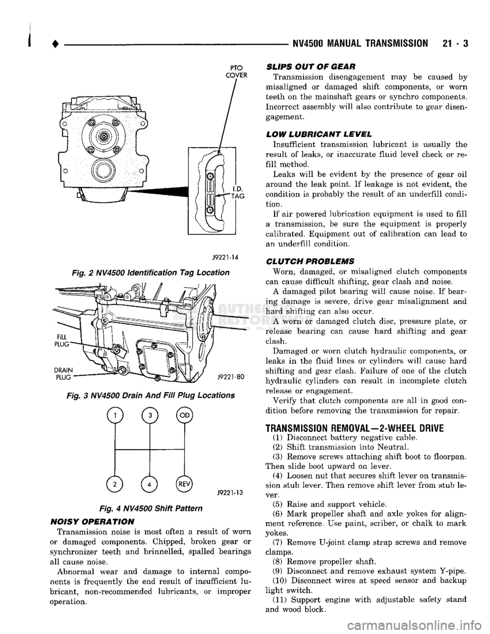
PTO
COVER
J9221-14
Fig. 2 NV4500 identification Tag Location
DRAIN
PLUG
J9221-80
Fig. 3 NV4500 Drain And Fill Plug Locations
o
0 ©
0 0©
J9221-13
Fig. 4 NV4500 Shitt Pattern
NOISY OPERATION Transmission noise is most often a result of worn
or damaged components. Chipped, broken gear or
synchronizer teeth and brinnelled, spalled bearings
all cause noise.
Abnormal wear and damage to internal compo
nents is frequently the end result of insufficient lu
bricant, non-recommended lubricants, or improper operation.
SLIPS
OUT OF
GEAR
Transmission disengagement may be caused by
misaligned or damaged shift components, or worn
teeth on the mainshaft gears or synchro components. Incorrect assembly will also contribute to gear disengagement.
LOW LUBRICANT LEWEL
Insufficient transmission lubricant is usually the
result of leaks, or inaccurate fluid level check or re
fill method.
Leaks will be evident by the presence of gear oil
around the leak point. If leakage is not evident, the
condition is probably the result of an underfill condi
tion.
If air powered lubrication equipment is used to fill
a transmission, be sure the equipment is properly
calibrated. Equipment out of calibration can lead to
an underfill condition.
CLUTCH
PROBLEMS
Worn, damaged, or misaligned clutch components
can cause difficult shifting, gear clash and noise.
A damaged pilot bearing will cause noise. If bear
ing damage is severe, drive gear misalignment and
hard shifting can also occur.
A worn or damaged clutch disc, pressure plate, or
release bearing can cause hard shifting and gear clash.
Damaged or worn clutch hydraulic components, or
leaks in the fluid lines or cylinders will cause hard shifting and gear clash. Failure of one of the clutch
hydraulic cylinders can result in incomplete clutch release or engagement.
Verify that clutch components are all in good con
dition before removing the transmission for repair.
TRANSMISSION
REMOVAL—2-WHEEL DRIVE
(1) Disconnect battery negative cable. (2) Shift transmission into Neutral.
(3) Remove screws attaching shift boot to floorpan.
Then slide boot upward on lever. (4) Loosen nut that secures shift lever on transmis
sion stub lever. Then remove shift lever from stub le
ver. (5) Raise and support vehicle.
(6) Mark propeller shaft and axle yokes for align
ment reference. Use paint, scriber, or chalk to mark
yokes.
(7) Remove U-joint clamp strap screws and remove
clamps. (8) Remove propeller shaft.
(9) Disconnect and remove exhaust system Y-pipe.
(10) Disconnect wires at speed sensor and backup
light switch. (11) Support engine with adjustable safety stand
and wood block.
Page 1006 of 1502
1
.
NW4500
MANUAL
TRANSMISSION 21 - 5 making transmission removal/installation easier.
Cylinder does not have to be removed completely. (28) Remove bolts attaching transmission to clutch
housing.
(29) Move transmission rearward until drive pin
ion clears clutch disc and release bearing. (30) Lower transmission and remove it from under
vehicle.
(31) If transmission will be overhauled, thoroughly
clean transmission exterior with solvent or steam
gun.
TRANSMISSION INSTALLATION-4-WHEEL DRIVE (1) Apply light coat of Mopar high temperature
bearing grease to contact surfaces of following com
ponents: • drive gear splines and pilot bearing hub • release bearing slide surface of front retainer
• pilot bearing
• release bearing bore
• release fork
• release fork ball stud
• propeller shaft slip yoke (2) Fill transmission with recommended lubricant.
Correct level is to bottom edge of fill plug hole. (3) Mount transmission on jack and position trans
mission under vehicle. Secure transmission to jack
with safety chains. (4) Raise transmission until drive gear is centered
in release bearing and clutch disc hub. (5) Move transmission forward and start drive gear
in release bearing and clutch disc. (6) Work transmission forward until seated against
clutch housing. Do not allow transmission to remain
unsupported after drive gear has entered clutch disc. (7) Install and tighten transmission-to-clutch hous
ing bolts to 108 N*m (80 ft. lbs.) torque. (8) Connect speed sensor and backup light switch
wires.
(9) Position transmission harness wires in clips on
shift cover. (10) Tighten slave cylinder attaching nuts and in
stall slave cylinder shield, if equipped.
(11) Install transmission mount on transmission or
rear crossmember. (12) Install rear crossmember.
(13) Remove transmission jack and engine support
fixture.
(14) Install transfer case on transmission jack. Se
cure transfer case to jack with safety chains. (15) Install new gasket on transmission adapter, or
coat adapter sealing surface with Mopar Gasket
Maker, or silicone adhesive sealer.
(16) Raise jack and align transfer case input gear
with transmission mainshaft.
(17) Move transfer case forward and seat it on
adapter.
(18) Install and tighten transfer case attaching
nuts to 47 N«m (35 ft. lbs.) torque.
(19) Connect transfer case shift lever to range le
ver on transfer case. (20) Align and connect propeller shafts. Tighten
U-joint clamp strap bolts to 19 N*m (170 in. lbs.)
torque.
(21) Check lubricant levels in transmission and
transfer case. Add lubricant if necessary.
(22) Install transfer case skid plate and crossmem
ber. Tighten attaching bolts/nuts to 41 N»m (30 ft. lbs.) torque.
(23) Install exhaust system components.
(24) Lower vehicle.
(25) Install transmission shift lever, boot and be
zel.
(26) Connect battery negative cable.
Page 1053 of 1502
21 - 52 G360
MANUAL
TRANSMISSION
• (12) Disconnect wires at vehicle speed sensor and
backup light switch.
(13) Disconnect transfer case shift lever from lever
on transfer case.
(14) Temporarily support transmission with adjust
able jack stand. Then support transfer case with
transmission jack.
(15) Remove nuts attaching transfer case to trans
mission adapter and move transfer case away from
transmission rear retainer.
(16) Lower transfer case and move it from under
vehicle. Remove transfer case from transmission jack and place transfer case on workbench.
(17) Support transmission with transmission jack.
Secure transmission to jack with safety chains. Then
remove jack stand previously used to support trans
mission.
(18) Spread clamps that secure switch wires to
transmission top cover and remove wires from clamps. Move wires aside to protect them and pro
vide working clearance.
(19) Remove bolts attaching transmission rear
mount to crossmember.
(20) On some models, it is necessary to remove
screws attaching fuel line clamps to driver side
frame rail. Three clamps must be removed to so fuel lines can be moved for access to crossmember bolts at
this side of frame rail.
(21) Remove left and right crossmember-to-frame
braces and remove crossmember.
(22) Remove clutch slave cylinder shield.
(23) Loosen clutch slave cylinder attaching nuts
until cylinder piston rod is clear of release lever (Fig.
20).
This reduces pressure on lever and release bear
ing making transmission removal/installation easier. Cylinder does not have to be removed completely.
(24) Remove bolts attaching transmission to clutch
housing and remove transmission. Rock transmission slightly to help free input shaft from clutch disc and
release bearing.
(25) Support engine with wood block and another
adjustable jack stand.
TRANSMISSION
INSTALLATION—4-WHEEL
DRIVE
(1) Mount transmission on jack stand. Secure
transmission to jack with safety chains.
(2) Apply light coat of Mopar high temperature
bearing grease to contact surfaces of input shaft (Fig. 20) and following components:
CAUTION:
Do not use
excessive
amounts
of
grease.
This
practice
could
result in contamination of the
clutch
disc.
• input shaft splines and pilot bearing hub
• release bearing slide surface of front retainer
• pilot bushing
• release bearing bore
• release fork
• release fork ball stud • propeller shaft slip yoke
(3) Align transmission and clutch housing. Move
transmission forward and start input shaft into re lease bearing and hub of clutch disc. (4) Rotate output shaft with socket or yoke to align
input shaft and clutch disc splines. If input shaft will
not rotate enough in neutral to align splines, it will
be necessary to shift transmission into third or fourth gear with screwdriver. (5) Seat transmission against clutch housing and
align bolt holes in transmission and housing. (6) Install and tighten transmission-to-clutch hous
ing bolts to 68 N-m (50 ft. lbs.). (7) Install rear crossmember and mount. Start all
crossmember bolts/nuts then tighten them to 68 N*m (50 ft. lbs.) torque. (8) Remove transmission jack.
(9) Install screws that attach fuel line clamps to
driver side frame rail. (10) Align clutch slave cylinder in housing and
tighten cylinder attaching nuts. (11) Install clutch slave cylinder shield.
(12) Secure backup light and vehicle speed sensor
wires in clips at top of transmission. Route wires across top of transmission to sensor and switch and
connect wires.
(13) Install gasket and transfer case on transmis
sion rear retainer. Tighten transfer case attaching
nuts to 47 N-m (35 ft. lbs.) torque. (14) Check transmission and transfer case lubri
cant levels. Add lubricant if necessary and install fill
plugs.
(15) Connect transfer case shift lever to lever on
transfer case.
(16) Align and install propeller shafts. Tighten
U-joint clamp bolts to 19 N-m (14 ft. lbs.). (17) Install skid plate and crossmember. Tighten
skid plate and crossmember bolts/nuts to 41 N—m
(30 ft. lbs.) torque.
(18) Lower vehicle.
(19) Shift transmission into neutral if necessary.
(20) Lubricate shift lever ball and collar with Mo
par all purpose grease. (21) Align notches in shift lever ball and collar
and insert shift lever in shift tower. (22) Press shift lever and collar downward and in
stall shift lever snap ring. (23) Install boot over shift lever and onto shift
tower and tighten boot clamp securely. (24) Install lower boot and plate assembly over
shift lever and onto floorpan. Position plate so large
notch is forward then install lower boot attaching screws. (25) Thread or bolt shift lever extension to shift le
ver. Slide upper boot down extension. Position boot on plate and install boot attaching screws. (26) Install shift knob on extension (if removed).
(27) Connect battery negative cable.
Page 1084 of 1502
•
AUTOMATIC TRANSiISSIO|-32RH/8iRH/37RH/42RH/4iRH
21 - 83 plate. The overdrive clutch also disengages the direct
clutch during 3-4 upshifts. As fluid pressure extends
the overdrive piston, the piston contacts the direct clutch hub pressing it rearward. This action com
presses the direct clutch spring relieving spring load on the clutch pack. The clutch is disengaged once
spring load is relieved.
The 3-4 accumulator cushions overdrive clutch en
gagement to smooth the transition into fourth gear.
The accumulator is charged at the same time as ap
ply pressure acts against the overdrive piston.
Converter clutch engagement in overdrive fourth
gear is controlled by sensor inputs to the powertrain
control module. In third gear above 25 mph, sensor inputs to the control module that determine clutch
engagement and shift timing are:
• coolant temperature (verifies minimum of 60° F)
• engine speed • vehicle speed
• throttle position
• manifold vacuum (MAP sensor)
Gearshift
Mechanism
The gear shift mechanism provides the same shift
positions used with 3-speed Chrysler transmissions
(P-R-N-D-2-1).
The shift into overdrive fourth gear range occurs
only after the transmission has completed the shift into D third gear range. No further movement of the
shift mechanism is required to complete the 3-4 shift.
The fourth gear upshift occurs automatically when
the overdrive control switch is in the ON position. Shift timing is determined by sensor inputs to the
engine controller.
Overdrive Control
Switch
The overdrive control switch is located in the in
strument panel. In the On position, automatic shifts
into fourth gear overdrive will occur. In the Off posi
tion, the switch overrides the engine controller pre
venting a shift to overdrive fourth gear range.
The switch has an indicator light that illuminates
when overdrive is turned off. The switch also resets
when the ignition key is turned to the OFF position so that the automatic overdrive feature is restored.
The use of fault codes is employed to help diagnose
the electronic components that operate the overdrive
unit and converter clutch.
HYDRAULIC
CONTROLS
The 42REJ/46RH hydraulic control system provides
fully automatic operation. The system performs five
basic functions which are: pressure supply, pressure regulation, flow control, clutch/band application, and
lubrication. 42RH/46RH system operation is similar to that de
scribed in the 32RH/36RH/37RH General Informa tion section. The main difference being fourth gear
operation which is covered here.
Pressure
Regulation
The pressure regulator valve maintains line pres
sure.
The amount of pressure developed is controlled
by throttle pressure which is dependent on the de gree of throttle opening. The regulator valve is lo
cated in the valve body.
The throttle valve determines line pressure and
shift speed. Governor pressure increases in propor
tion to vehicle speed. The throttle valve controls up shift and downshift speeds by regulating pressure
according to throttle position.
Flow
Control And Lubrication The manual valve is operated by the gearshift link
age and provides the operating range selected by the
driver.
The 1-2 shift valve provides 1-2 or 2-1 shifts and
the 2-3 shift valve provides 2-3 or 3-2 shifts.
The kickdown valve provides forced 3-2 or 3-1
downshifts depending on vehicle speed. Downshifts
occur when the throttle is opened beyond downshift
detent position which is just before wide open throt
tle.
The 2-3 valve throttle pressure plug provides 3-2
downshifts at varying throttle openings depending on
vehicle speed.
The 1-2 shift control valve transmits 1-2 shift pres
sure to the accumulator piston. This controls kick-
down band capacity on 1-2 upshifts and 3-2 downshifts.
The 3-4 shift valve, shuttle valve, timing valve and
accumulator are only actuated when the overdrive
solenoid is energized.
The solenoid contains a check ball that controls a
vent port to the 3-4 valve. The check ball either di
verts line pressure away from or directly to, the 3-4 shift valve. Energizing the solenoid causes the check
ball to close the vent port allowing line pressure to act upon the 3-4 upshift valve.
The limit valve determines maximum speed at
which a 3-2 part throttle kickdown can be made. Some transmissions do not have the limit valve and
maximum speed for a 3-2 kickdown is at the detent
position.
The 2-3 shuttle valve has two functions. First is
fast front band release and smooth engagement dur ing lift-foot 2-3 upshifts. The second is to regulate
front clutch and band application during 3-2 down
shifts.
The 3-4 shuttle valve uses a combination of throt
tle and governor pressure to control the rate of over
drive piston apply and release. This is done to
maintain shift quality at varying throttle openings.
Page 1086 of 1502
•
AUTOMATIC TRANSiISSiOi-32RH/38RH/37RH/42RH/4eRH
21 - 81 AUTOMATIC TRANSMISSION DIAGNOSIS AND TESTING
INDEX
page
Air Testing Clutch
and
Band Operation
91
Analyzing
the
Road Test
87
Converter Housing Fluid Leak Diagnosis
.......
92
Converter
Stall
Test
90
Diagnosis
Charts
and
Hydraulic Flow Diagrams
. . 95
Fluid Contamination
86
Fluid Level
and
Condition
85
GENERAL
INFORMATION
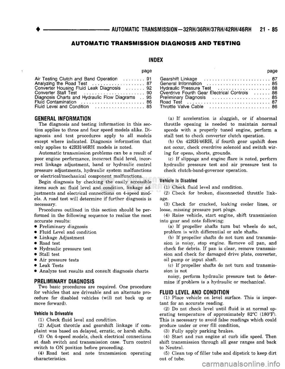
The diagnosis
and
testing information
in
this sec
tion applies
to
three
and
four speed models alike.
Di
agnosis
and
test procedures apply
to all
models
except where indicated. Diagnosis information that
only applies
to
42RH/46RH models
is
noted.
Automatic transmission problems
can be a
result
of
poor engine performance, incorrect fluid level, incor
rect linkage adjustment, band
or
hydraulic control
pressure adjustments, hydraulic system malfunctions
or electrical/mechanical component malfunctions.
Begin diagnosis
by
checking
the
easily accessible
items such
as:
fluid level
and
condition, linkage
ad
justments
and
electrical connections
on
4-speed mod
els.
A
road test will determine
if
further diagnosis
is
necessary. Procedures outlined
in
this section should
be
per
formed
in the
following sequence
to
realize
the
most accurate results:
• Preliminary diagnosis
• Fluid Level
and
condition • Linkage Adjustment
• Road test
• Hydraulic pressure test • Stall test
•
Air
pressure tests
• Leak Tests
• Analyze test results
and
consult diagnosis charts
PRELIMINARY
DIAGNOSIS
Two basic procedures
are
required.
One
procedure
for vehicles that
are
driveable
and an
alternate pro cedure
for
disabled vehicles (will
not
back
up or
move forward).
Vehicle
Is
Driveable
(1) Check fluid level
and
condition.
(2) Adjust throttle
and
gearshift linkage
if
com
plaint
was
based
on
delayed, erratic,
or
harsh shifts.
(3)
On
4-speed models, check electrical connections
at dash switch
and
transmission case. Turn control
switch
to ON
position before proceeding. (4) Road test
and
note transmission operating
characteristics.
page
Gearshift Linkage
87
General
Information
85
Hydraulic Pressure Test
88
Overdrive Fourth Gear
Electrical
Controls
......
86
Preliminary Diagnosis
85
Road
Test
87
Throttle
Valve Cable
86
(a)
If
acceleration
is
sluggish,
or if
abnormal
throttle opening
is
needed
to
maintain normal speeds with
a
properly tuned engine, perform
a
stall test
to
check converter clutch operation. (b)
On
42RH/46RH,
if
fourth gear upshift does
not occur, check overdrive solenoid
and
switch wir ing
for
opens, shorts, grounds.
(c)
If
slippage
and
engine flare
is
noted, perform
hydraulic pressure test
and air
pressure test
to
check clutch-band-governor operation.
Vehicle
Is
Disabled
(1) Check fluid level
and
condition.
(2) Check
for
broken, disconnected throttle link
age.
(3) Check
for
cracked, leaking cooler lines,
or
loose, missing pressure port plugs.
(4) Raise vehicle, start engine, shift transmission
into gear
and
note following:
(a)
If
propeller shafts turn
but
wheels
do not,
problem
is
with differential
or
axle shafts. (b)
If
propeller shafts
do not
turn
and
transmis
sion
is
noisy, stop engine. Remove
oil pan, and
check
for
debris.
If pan is
clear, remove transmis
sion
and
check
for
damaged drive plate, converter,
oil pump
or
input shaft.
(c)
If
propeller shafts
do not
turn
and
transmis
sion
is not
noisy, perform hydraulic pressure test
to
deter
mine
if
problem
is a
hydraulic
or
mechanical.
FLUID LEVEL AND CONDITION
(1) Place vehicle
on
level surface. This
is
impor
tant
for an
accurate reading. (2)
Do not
check level until fluid
is at
normal
op
erating temperature
of
approximately 82°C (180°F).
This
is
necessary
to
avoid false readings which could
produce under
or
over fill condition, (3) Fully apply parking brakes.
(4) Start
and run
engine
at
curb idle speed. Then
shift transmission through
all
gear ranges
and
back
to Neutral. (5) Clean
top of
filler tube
and
dipstick
to
keep dirt
out
of
tube.
Page 1087 of 1502
21 - 86
AUTOMATIC
TRANSMISSION-32RH/36RH/37RH/42RH/46RH
•
(6)
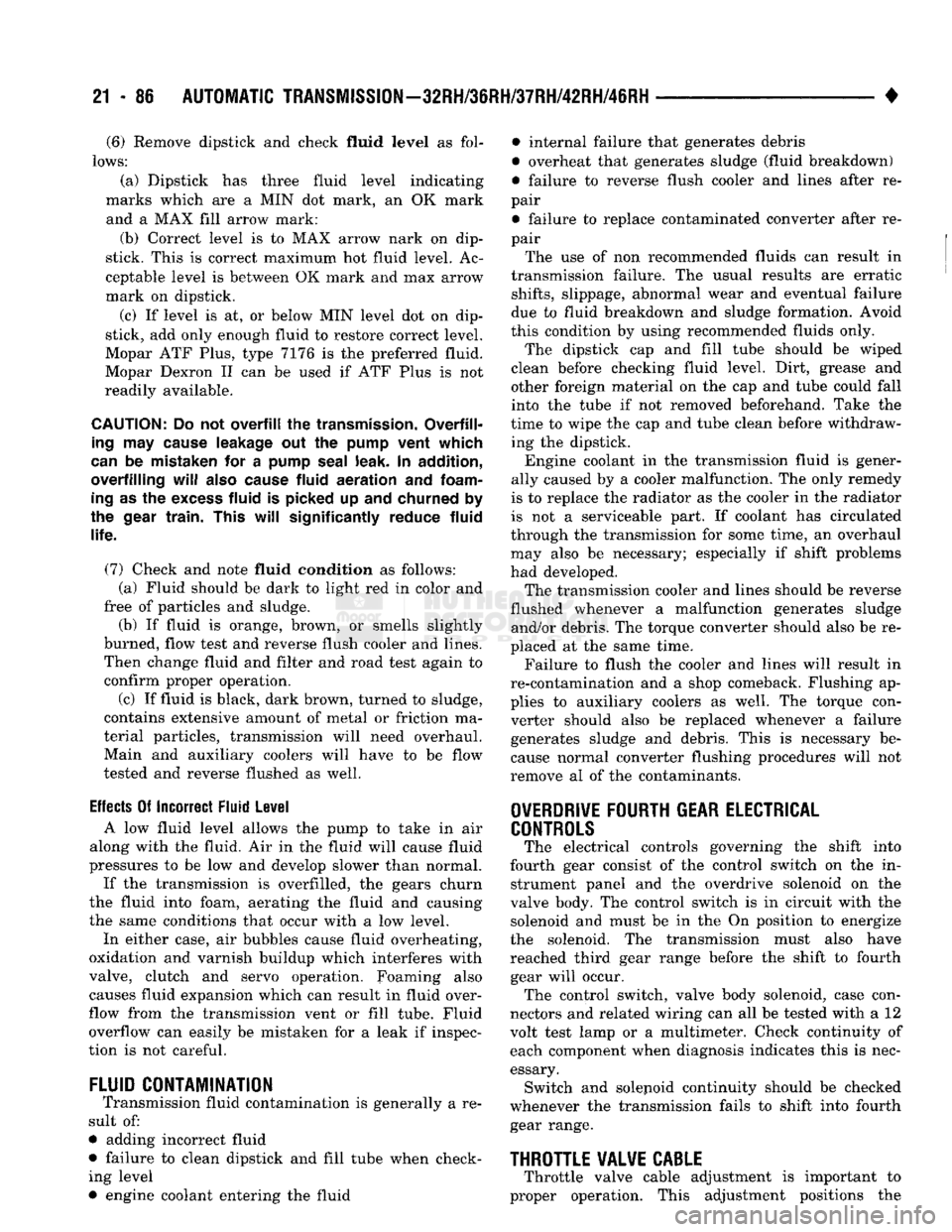
Remove dipstick and check fluid
level
as fol
lows:
(a) Dipstick has three fluid level indicating
marks which are a MIN dot mark, an OK mark and a MAX fill arrow mark:
(b) Correct level is to MAX arrow nark on dip
stick. This is correct maximum hot fluid level. Ac
ceptable level is between OK mark and max arrow
mark on dipstick.
(c) If level is at, or below MIN level dot on dip
stick, add only enough fluid to restore correct level.
Mopar ATF Plus, type 7176 is the preferred fluid.
Mopar Dexron II can be used if ATF Plus is not
readily available.
CAUTION:
Do not
overfill
the
transmission.
Overfill
ing
may
cause
leakage out the
pump
vent which
can
be mistaken for a
pump
seal
leak. In addition,
overfilling
will
also
cause
fluid
aeration
and
foam
ing
as the
excess
fluid is picked up and churned by
the
gear
train.
This
will
significantly
reduce fluid
life.
(7) Check and note fluid condition as follows: (a) Fluid should be dark to light red in color and
free of particles and sludge.
(b) If fluid is orange, brown, or smells slightly
burned, flow test and reverse flush cooler and lines. Then change fluid and filter and road test again to
confirm proper operation.
(c) If fluid is black, dark brown, turned to sludge,
contains extensive amount of metal or friction ma
terial particles, transmission will need overhaul. Main and auxiliary coolers will have to be flow
tested and reverse flushed as well.
Effects
Of Incorrect Fluid Level A low fluid level allows the pump to take in air
along with the fluid. Air in the fluid will cause fluid
pressures to be low and develop slower than normal.
If the transmission is overfilled, the gears churn
the fluid into foam, aerating the fluid and causing
the same conditions that occur with a low level.
In either case, air bubbles cause fluid overheating,
oxidation and varnish buildup which interferes with
valve, clutch and servo operation. Foaming also causes fluid expansion which can result in fluid over
flow from the transmission vent or fill tube. Fluid
overflow can easily be mistaken for a leak if inspec
tion is not careful.
FLUID
CONTAMINATION
Transmission fluid contamination is generally a re
sult of:
• adding incorrect fluid
• failure to clean dipstick and fill tube when check ing level
• engine coolant entering the fluid • internal failure that generates debris
• overheat that generates sludge (fluid breakdown)
• failure to reverse flush cooler and lines after re
pair
• failure to replace contaminated converter after re
pair
The use of non recommended fluids can result in
transmission failure. The usual results are erratic
shifts,
slippage, abnormal wear and eventual failure
due to fluid breakdown and sludge formation. Avoid
this condition by using recommended fluids only.
The dipstick cap and fill tube should be wiped
clean before checking fluid level. Dirt, grease and
other foreign material on the cap and tube could fall
into the tube if not removed beforehand. Take the
time to wipe the cap and tube clean before withdraw ing the dipstick.
Engine coolant in the transmission fluid is gener
ally caused by a cooler malfunction. The only remedy
is to replace the radiator as the cooler in the radiator
is not a serviceable part. If coolant has circulated
through the transmission for some time, an overhaul may also be necessary; especially if shift problems
had developed.
The transmission cooler and lines should be reverse
flushed whenever a malfunction generates sludge and/or debris. The torque converter should also be re
placed at the same time.
Failure to flush the cooler and lines will result in
re-contamination and a shop comeback. Flushing ap
plies to auxiliary coolers as well. The torque con verter should also be replaced whenever a failure
generates sludge and debris. This is necessary be
cause normal converter flushing procedures will not
remove al of the contaminants.
OVERDRIVE
FOURTH
GEAR
ELECTRICAL
CONTROLS
The electrical controls governing the shift into
fourth gear consist of the control switch on the in strument panel and the overdrive solenoid on the
valve body. The control switch is in circuit with the solenoid and must be in the On position to energize
the solenoid. The transmission must also have
reached third gear range before the shift to fourth gear will occur. The control switch, valve body solenoid, case con
nectors and related wiring can all be tested with a 12
volt test lamp or a multimeter. Check continuity of each component when diagnosis indicates this is nec
essary. Switch and solejioid continuity should be checked
whenever the transmission fails to shift into fourth
gear range.
THROTTLE
VALVE
CABLE
Throttle valve cable adjustment is important to
proper operation. This adjustment positions the
Page 1088 of 1502
AUTOMATIC TRANSMISSION—32RH/36RH/37RH/42RH/46RH
21 - 87
throttle valve which controls shift speed, quality and
part throttle downshift sensitivity. If cable setting is too short, early shifts and slip
page between shifts may occur. If the setting is too long, shifts may be delayed and part throttle downshifts may be very sensitive. Refer to the In-Vehicle
Service section for adjustment procedure.
GEARSHIFT LINKAGE
Gearshift linkage adjustment is important because
it positions the valve body manual valve. Incorrect
adjustment will cause creeping in Neutral, prema
ture clutch wear, delayed engagement in any gear, or a no-start in Park or Neutral position.
Proper operation of the neutral start switch will
provide a quick check of linkage adjustment. Refer to
the In-Vehicle Service section for adjustment proce
dure.
ROAD TEST
Before road testing, be sure the fluid level and all
linkage adjustments have been checked and adjusted
if necessary. Observe engine performance during the road test.
A poorly tuned engine will not allow an accurate analysis of transmission operation. Operate the transmission in all gear ranges. Check
for slippage and shift variations. Note whether the shifts are harsh, spongy, delayed, early, or if part
throttle downshifts are sensitive. Watch closely for slippage or engine flare which
usually indicates clutch, band or overrunning clutch
problems. If the condition is advanced, an overhaul
may be necessary to restore normal operation. A slipping clutch or band can often be determined
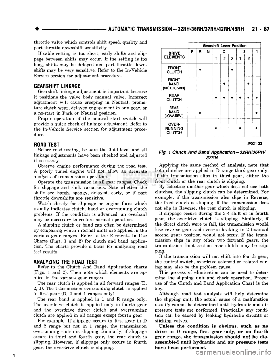
by comparing which internal units are applied in the various gear ranges. Refer to the Elements In Use Charts (Figs. 1 and 2) for clutch and band applica
tion. The charts provide a basis for analyzing road
test results.
ANALYZING
THE
ROAD TEST
Refer to the Clutch And Band Application charts
(Figs.
1 and 2). Then note which elements are ap
plied in the various gear ranges. The rear clutch is applied in all forward ranges (D,
2,
1). The transmission overrunning clutch is applied
in first gear (D, 2 and 1 ranges only). The rear band is applied in 1 and R range only.
The overdrive clutch is applied only in fourth gear and the overdrive direct clutch and overrunning
clutch are applied in all ranges except fourth gear. For example: If slippage occurs in first gear in D
and 2 range but not in 1 range, the transmission
overrunning clutch is slipping. Similarly, if slippage
occurs in third and fourth gear, the rear clutch is
slipping. However, if slippage only occurs in fourth gear, the overdrive clutch is slipping.
Gearshift
Lever
Position
DRIVE
ELEMENTS P
R
N
D 2 1
DRIVE
ELEMENTS
1 2 3 1
2
FRONT
CLUTCH
•
•
FRONT BAND
(KICKDOWN)
•
•
REAR
CLUTCH
REAR
BAND
(LOW-REV.)
•
•
OVER
RUNNING CLUTCH
•
• •
J9021-33
Fig.
1
Clutch
And
Band
Application—32RH/36RH/
37RH
Applying the same method of analysis, note that
both clutches are applied in D range third gear only. If the transmission slips in third gear, either the
front clutch or the rear clutch is slipping. By selecting another gear which does not use both
clutches, the slipping clutch can be determined. For example, if the transmission also slips in Reverse,
the front clutch is slipping. If the transmission does not slip in Reverse, the rear clutch is slipping.
If slippage occurs during the 3-4 shift or in fourth
gear, the overdrive clutch is slipping. Similarly, if
the direct clutch were to fail, the transmission would lose reverse gear and overrun braking in 2 (manual second gear) position would not occur. If the trans
mission slips in any other two forward gears, the
transmission front section rear clutch may be slip
ping.
If the transmission will not shift into fourth gear,
the control switch, overdrive solenoid or related wir
ing may also be the problem cause.
This process of elimination can be used to deter
mine the slipping unit and check operation. Proper use of the Clutch and Band Application Chart is the
key.
Although road test analysis will help determine
the slipping unit, the actual cause of a malfunction usually cannot be determined until hydraulic and air
pressure tests are performed. Practically any condi tion can be caused by leaking hydraulic circuits or sticking valves.
Unless the condition is obvious, such as no
drive in D range, first gear only, or no fourth
gear range, the transmission should not be dis
assembled until hydraulic and air pressure tests
have been performed.
Page 1089 of 1502
21 - 88
AUTOMATIC
TRANSMISSION—32RH/36RH/37RH/42RH/46RH
•
SHIFT
LEVER
POSITION
TRANSMISSION
CLUTCH
ES
AND
BANDS
OVERDRIVE
CLUTCHES
SHIFT
LEVER
POSITION FRONT
CLUTCH FRONT
BAND
REAR
CLUTCH
REAR
BAND
OVERRUN.
CLUTCH
OVERDRIVE
CLUTCH DIRECT
CLUTCH
OVERRUN.
CLUTCH
Reverse
X X
X
Drive
Range
First
Second
Third
Fourth
X
X X
X X
X X
X X
X
X X
X
X
2-Range:
(Manual
Second):
Second
First
X
X
X X X
X
X
X
1-Range
(Manual
Low):
First
X X X X
X
J9221-22
Fig.
2
Clutch
And
Band
Application-42RH/46RH
HYDRAULIC PRESSURE
TEST
«\ \\\REAR
\\v
-
LINE
FRONT
' M
SERVO
\\ PRESSURE
/S—'
SERVO
PRESSURE
TEST
PORT
LOCATIONS
\\\
W \\\ PO.RT, \ i PORT
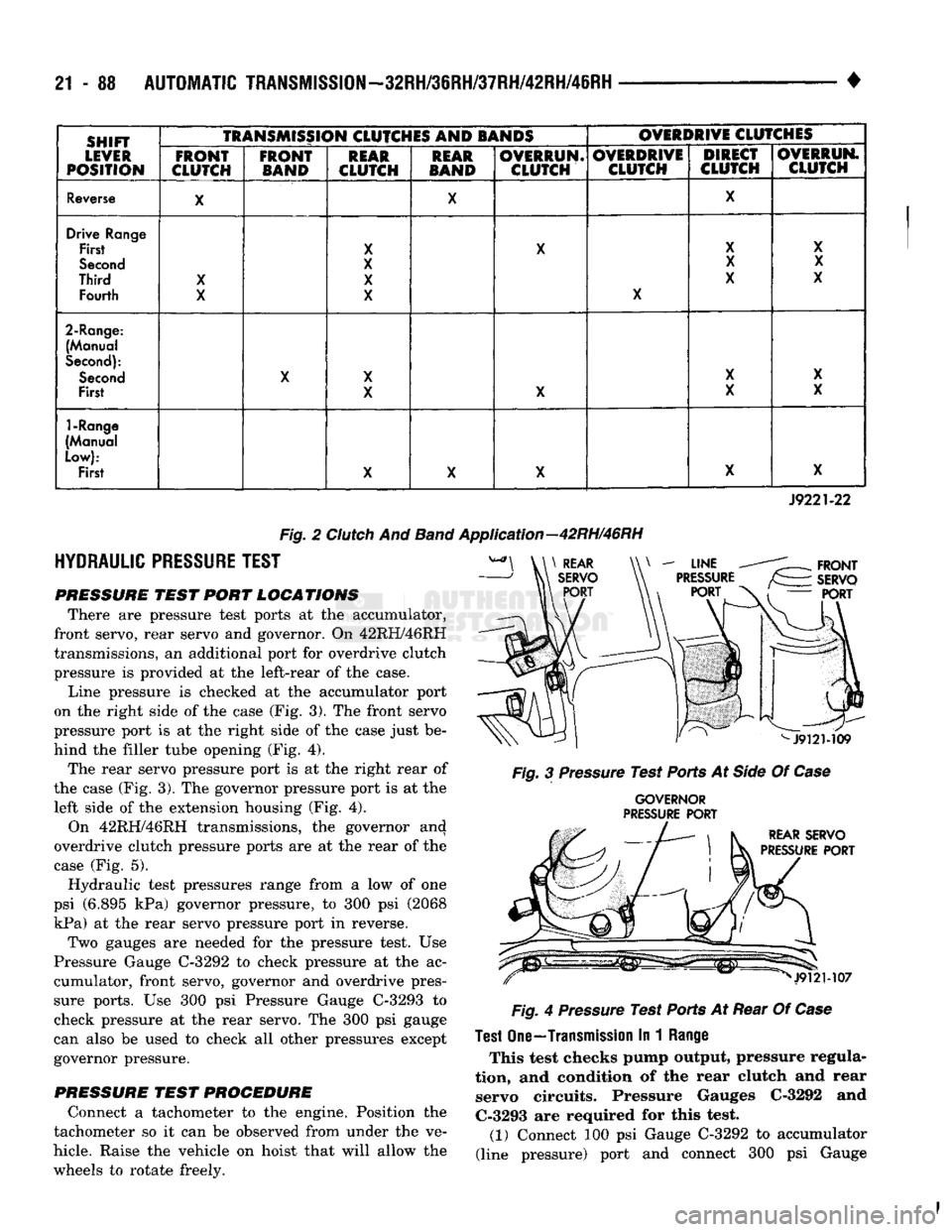
There are pressure test ports at the accumulator,
front servo, rear servo and governor. On 42RH/46RH
transmissions, an additional port for overdrive clutch
pressure is provided at the left-rear of the case. Line pressure is checked at the accumulator port
on the right side of the case (Fig. 3). The front servo
pressure port is at the right side of the case just be
hind the filler tube opening (Fig. 4). The rear servo pressure port is at the right rear of
the case (Fig. 3). The governor pressure port is at the left side of the extension housing (Fig. 4). On 42RH/46RH transmissions, the governor and
overdrive clutch pressure ports are at the rear of the
case (Fig. 5). Hydraulic test pressures range from a low of one
psi (6.895 kPa) governor pressure, to 300 psi (2068
kPa) at the rear servo pressure port in reverse. Two gauges are needed for the pressure test. Use
Pressure Gauge C-3292 to check pressure at the ac
cumulator, front servo, governor and overdrive pres
sure ports. Use 300 psi Pressure Gauge C-3293 to check pressure at the rear servo. The 300 psi gauge
can also be used to check all other pressures except
governor pressure.
PRESSURE
TEST
PROCEDURE
Connect a tachometer to the engine. Position the
tachometer so it can be observed from under the ve
hicle. Raise the vehicle on hoist that will allow the wheels to rotate freely.
F
Fig.
3
Pressure
Test Ports At
Side
Of
Case
GOVERNOR
PRESSURE
PORT
Fig.
4
Pressure
Test Ports At Rear Of
Case
Test
One—Transmission
In 1
Range
This test checks pump output, pressure regula
tion,
and condition of the rear clutch and rear servo circuits. Pressure Gauges C-3292 and C-3293 are required for this test.
(1) Connect 100 psi Gauge C-3292 to accumulator
(line pressure) port and connect 300 psi Gauge