1993 DODGE TRUCK check engine
[x] Cancel search: check enginePage 1132 of 1502
•
IN-VEHICLE
SERVICE-32RH/36RH/37RH/42RH/46RH
21 - 131
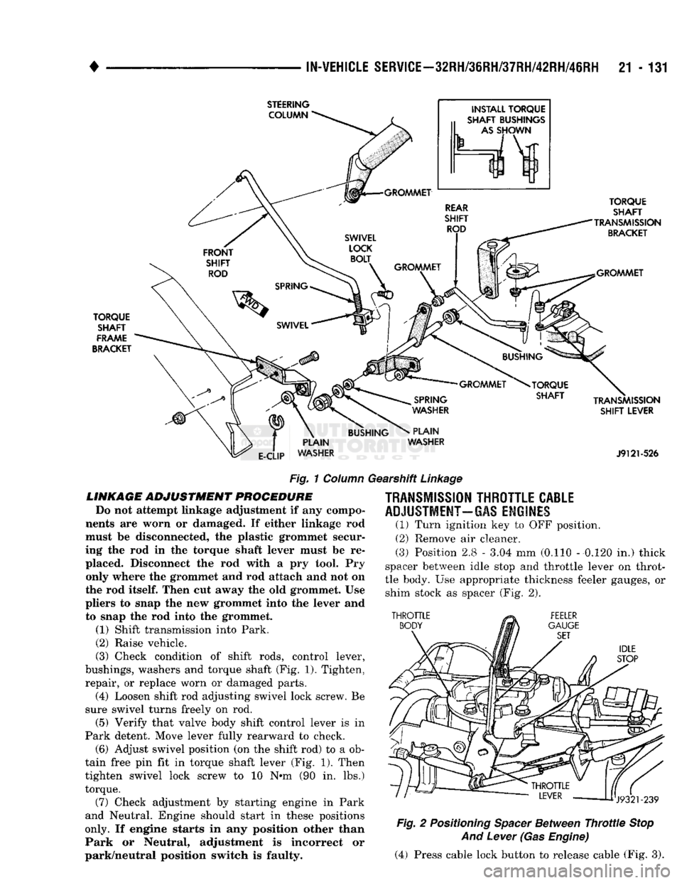
Fig.
1
Column
Gearshift
Linkage
LINKAGE
ADJUSTMENT
PROCEDURE
Do
not
attempt
linkage
adjustment
if any
compo
nents
are
worn
or
damaged.
If
either linkage
rod
must
be
disconnected,
the plastic
grommet secur
ing
the rod in the
torque shaft lever must
be re
placed. Disconnect
the rod
with
a pry
tool.
Pry
only where
the
grommet
and rod
attach
and not on
the
rod
itself.
Then
cut
away
the old
grommet.
Use
pliers
to
snap
the new
grommet into
the
lever
and
to snap
the rod
into
the
grommet.
(1) Shift transmission into Park.
(2) Raise vehicle.
(3) Check condition
of
shift rods, control lever,
bushings, washers
and
torque shaft
(Fig.
1). Tighten,
repair,
or
replace worn
or
damaged parts. (4) Loosen shift rod adjusting swivel lock screw.
Be
sure swivel turns freely
on rod.
(5) Verify that valve body shift control lever
is in
Park detent. Move lever fully rearward
to
check. (6) Adjust swivel position
(on the
shift rod)
to a ob
tain free
pin fit in
torque shaft lever
(Fig. 1).
Then
tighten swivel lock screw
to 10 N»m (90 in. lbs.)
torque.
(7) Check adjustment
by
starting engine
in
Park
and Neutral. Engine should start
in
these positions
only. If
engine starts
in any
position other than
Park
or
Neutral, adjustment
is
incorrect
or
park/neutral position switch
is
faulty.
TRANSMISSION
THROTTLE
CABLE
ADJUSTMENT-GAS
ENGINES
(1)
Turn ignition
key to OFF
position.
(2)
Remove
air
cleaner.
(3)
Position 2.8
-
3.04
mm
(0.110
-
0.120
in.)
thick
spacer between idle stop
and
throttle lever
on
throt
tle body.
Use
appropriate thickness feeler gauges,
or
shim stock
as
spacer
(Fig. 2).
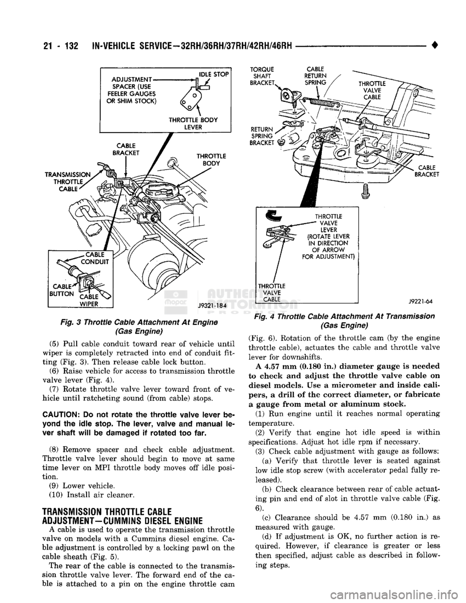
Fig.
2
Positioning
Spacer
Between
Throttle
Stop
And
Lever
(Gas
Engine)
(4) Press cable lock button
to
release cable
(Fig. 3).
Page 1133 of 1502
21 - 132
IN-VEHICLE
SERVICE-32RH/36RH/37RH/42RH/46RH
•
IDLE STOP
ADJUSTMENT
• —/
SPACER (USE
Hk±s
FEELER
GAUGES
/o)
OR SHIM STOCK)
THROTTLE BODY LEVER TRANSMISSION
THROTTLE CABLE
TORQUE
SHAFT
BRACKET.
CABLE
RETURN
SPRING
^
CABLE
CONDUIT
CABLE
^1
BUTTON
1
CABLE
\>
WIPER
J932M84
Fig.
3
Throttle
Cable Attachment At
Engine
(Gas
Engine)
(5) Pull cable conduit toward rear of vehicle until
wiper is completely retracted into end of conduit fit
ting (Fig. 3). Then release cable lock button. (6) Raise vehicle for access to transmission throttle
valve lever (Fig. 4).
(7) Rotate throttle valve lever toward front of ve
hicle until ratcheting sound (from cable) stops.
CAUTION:
Do not
rotate
the
throttle
valve
lever
be
yond
the
idle
stop.
The
lever,
valve
and
manual
le
ver
shaft
will
be
damaged
if
rotated
too far.
(8) Remove spacer and check cable adjustment.
Throttle valve lever should begin to move at same
time lever on MPI throttle body moves off idle posi
tion.
(9) Lower vehicle.
(10) Install air cleaner.
TRANSMISSION
THROTTLE
CABLE
ADJUSTMENT-CUMMINS
DIESEL
ENGINE
A cable is used to operate the transmission throttle
valve on models with a Cummins diesel engine. Ca
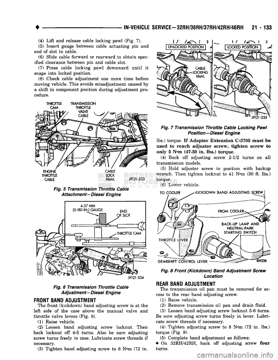
ble adjustment is controlled by a locking pawl on the cable sheath (Fig. 5). The rear of the cable is connected to the transmis
sion throttle valve lever. The forward end of the ca
ble is attached to a pin on the engine throttle cam
RETURN
SPRING
/
BRACKET
^
CABLE
BRACKET
THROTTLE
VALVE
LEVER
(ROTATE
LEVER
IN
DIRECTION
OF
ARROW
FOR
ADJUSTMENT)
THROTTLE
VALVE
CABLE
J9221-64
Fig.
4
Throttle
Cable Attachment At
Transmission
(Gas
Engine)
(Fig. 6). Rotation of the throttle cam (by the engine
throttle cable), actuates the cable and throttle valve lever for downshifts. A 4.57 mm (0.180 in.) diameter gauge is needed
to check and adjust the throttle valve cable on diesel models. Use a micrometer and inside cali
pers,
a drill of the correct diameter, or fabricate a gauge from metal or aluminum stock. (1) Run engine until it reaches normal operating
temperature.
(2) Verify that engine hot idle speed is within
specifications. Adjust hot idle rpm if necessary.
(3) Check cable adjustment with gauge as follows: (a) Verify that throttle lever is seated against
low idle stop screw (with accelerator pedal fully re leased).
(b) Check clearance between rear of cable actuat
ing pin and end of slot in throttle valve cable (Fig.
6).
(c) Clearance should be 4.57 mm (0.180 in.) as
measured with gauge. (d) If adjustment is OK, no further action is re
quired. However, if clearance is greater or less
then specified, adjust cable as described in follow ing steps.
Page 1134 of 1502
•
IN-VEHICLE SERVICE-32RH/36RH/37RH/42RH/46RH
21 - 133 (4) Lift and release cable locking pawl (Fig. 7).
(5) Insert gauge between cable actuating pin and
end of slot in cable. (6) Slide cable forward or rearward to obtain spec
ified clearance between pin and cable slot.
(7) Press cable locking pawl downward until it
snaps into locked position.
(8) Check cable adjustment one more time before
moving vehicle. This avoids misadjustment caused by
a shift in component position during adjustment pro
cedure.
THROTTLE
TRANSMISSION
CAM
THROTTLE
VALVE
i j
/\&s/,
CABLE
m
ENGINE
THROTTLE
CABLE CABLE
LOCK PAWL
J9121-533
Fig.
5
Transmission
Throttle
Cable
Attachment—Diesel
Engine
4.57
MM
(0.180
IN.) GAUGE
J9121-534
Fig.
6
Transmission
Throttle
Cable
Adjustment—Diesel
Engine
FRONT BAND ADJUSTMENT
The front (kickdown) band adjusting screw is at the
left side of the case above the manual valve and
throttle valve levers (Fig. 8). (1) Raise vehicle.
(2) Loosen band adjusting screw locknut. Then
back locknut off 4-5 turns. Also be sure adjusting screw turns freely in case. Lubricate screw threads if
necessary. (3) Tighten band adjusting screw to 8 Nrm (72 in.
J9121
-535
Fig.
7
Transmission
Throttle
Cable
Locking
Pawl
Position—Diesel
Engine
lbs.) torque. If Adapter Extension C-3705 must be
used to reach adjuster screw, tighten screw to only 5 N»m (47-50 in. lbs.) torque.
(4) Back off adjusting screw 2-1/2 turns on all
transmission models. (5) Hold adjuster screw in position with backup
wrench. Then tighten locknut to 41 N»m (30 ft. lbs.)
torque. (6) Lower vehicle.
TO COOLER
KICKDOWN BAND ADJUSTING SCREW
GEARSHIFT CONTROL LEVER
RH256
Fig.
8 Front (Kickdown)
Band
Adjustment
Screw
Location
REAR
BAND ADJUSTMENT
The transmission oil pan must be removed for ac
cess to the rear band adjusting screw. (1) Raise vehicle.
(2) Remove transmission oil pan and drain fluid.
(3) Loosen band adjusting screw locknut 5-6 turns.
Be sure adjusting screw turns freely in lever. Lubri
cate screw threads if necessary. (4) Tighten adjusting screw to 8 Nnn (72 in. lbs.)
torque (Fig. 9). (5) Complete band adjustment as follows:
• On 32RH/42RH, back off adjusting screw four
turns.
Page 1142 of 1502
•
IN-VEHICLE
SERVICE-32RH/36RH/37RH/42RH/46RH
21 - 141 (2) Position drain pan under cooler pressure line to
catch material flushed through cooler and lines. (3) Reverse flush cooler using hand operated suc
tion gun filled with mineral spirits. Insert gun nozzle (or hose) into cooler return line. Then force mineral
spirits into line and through cooler. (4) Continue reverse flushing until fluid exiting
cooler pressure line is clear and free from debris. Re
place cooler if fluid cannot be pumped through. (5) Clear flushing materials from cooler and lines
with short pulses of compressed air. Insert air gun nozzle into cooler return line and continue short air pulses until all fluid is cleared from cooler and lines. (6) Pump one quart of fresh automatic transmission
fluid through cooler and lines before reconnecting lines.
CHECKING COOLER FLUID FLOW Cooler flow is checked, by measuring the amount of
fluid pumped through the cooler in a specified time
by the transmission oil pump. (1) Disconnect cooler return line from transmission
and place it in one quart test container.
(2) Add extra quart of fluid to transmission.
(3) Use stopwatch to check test time.
(4) Shift into Neutral.
(5) Start and run engine at curb idle speed and
note cooler flow. A minimum of one quart (0.9 liter)
of fluid should flow into test container in 20 seconds. (6) If fluid flow is intermittent, flows less than one
quart in 20 seconds, or fails to flow at all, cooler is
plugged or damaged and should be replaced.
MAIN COOLER REPLACEMENT The main transmission cooler is located in the ra
diator lower tank. The cooler is not a serviceable component. If the cooler is damaged in any way, the
radiator will have to be replaced.
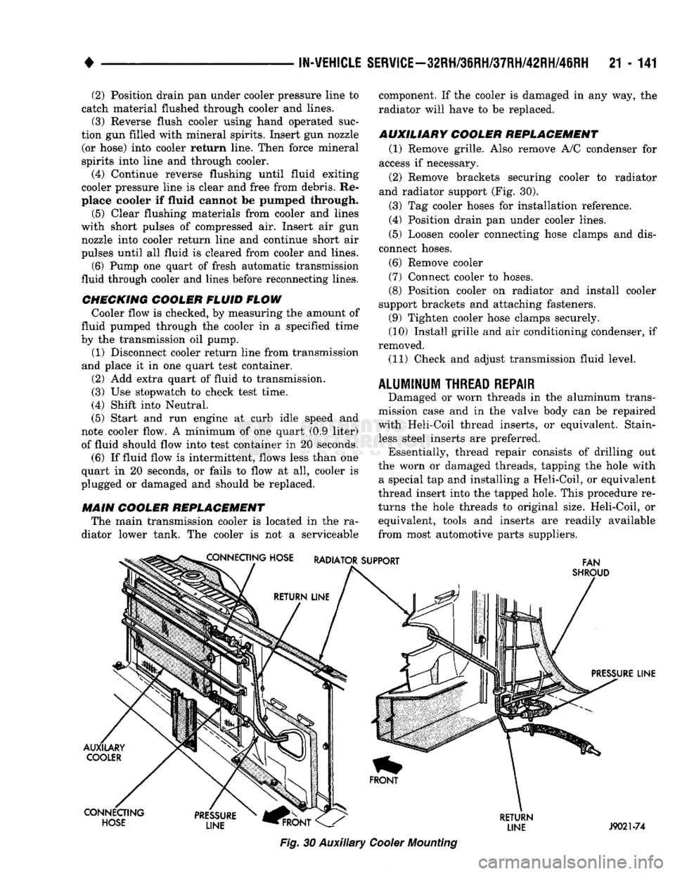
AUXILIARY COOLER REPLACEMENT (1) Remove grille. Also remove A/C condenser for
access if necessary.
(2) Remove brackets securing cooler to radiator
and radiator support (Fig. 30).
(3) Tag cooler hoses for installation reference.
(4) Position drain pan under cooler lines.
(5) Loosen cooler connecting hose clamps and dis
connect hoses.
(6) Remove cooler
(7) Connect cooler to hoses.
(8) Position cooler on radiator and install cooler
support brackets and attaching fasteners. (9) Tighten cooler hose clamps securely.
(10) Install grille and air conditioning condenser, if
removed.
(11) Check and adjust transmission fluid level.
ALUMINUM
THREAD
REPAIR
Damaged or worn threads in the aluminum trans
mission case and in the valve body can be repaired
with Heli-Coil thread inserts, or equivalent. Stain less steel inserts are preferred. Essentially, thread repair consists of drilling out
the worn or damaged threads, tapping the hole with a special tap and installing a Heli-Coil, or equivalent
thread insert into the tapped hole. This procedure re
turns the hole threads to original size. Heli-Coil, or equivalent, tools and inserts are readily available
from most automotive parts suppliers. CONNECTING HOSE RADIATOR SUPPORT
FAN
SHROUD
PRESSURE LINE
AUXILARY COOLER
CONNECTING HOSE PRESSURE
LINE
HFRONT
Fig.
30 Auxiliary
Cooler
Mounting
RETURN
LINE J9021-74
Page 1147 of 1502
21 - 146
AUTOMATIC
TRANSMISSION REMOVAL
AND
INSTALLATION
• • Use a D.C. welder set at straight polarity, or use
an A.C. welder if the proper electrode is available
• Use 1/8 inch diameter welding rod and a welding
current of 80 to 125 amps. • Direct arc at intersection of gear and front cover at
an angle of 45° from rear face of gear.
(6)
Weld new ring gear to torque converter front
cover. Take care to place same amount of weld mate
rial (or as nearly as possible) in original weld loca
tions.
This is essential in maintaining converter
balance. Position welds alternately on opposite sides of converter and ring gear to minimize distortion.
(7) Inspect gear teeth and remove any nicks, raised
metal, weld spatter, or rough surfaces.
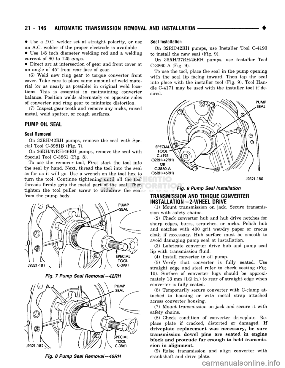
PUMP
OIL
SEAL
Seal
Removal
On 32RH/42RH pumps, remove the seal with Spe
cial Tool C-3981B (Fig. 7).
On 36RH/37RH/46RH pumps, remove the seal with
Special Tool C-3861 (Fig. 8). To use the remover tool, First start the tool into
the seal by hand. Next, thread the tool into the seal as far as it will go. Use a wrench on the tool hex to
turn the tool. Continue tightening until all the tool
threads firmly grip the metal part of the seal. Then
tighten the tool puller screw to withdraw the seal
from the pump body.
Fig. 7 Pump Seal Removal—42RH Fig. 8 Pump Seal Removal—46RH
Seal
Installation
On 32RH/42RH pumps, use Installer Tool C-4193
to install the new seal (Fig. 9).
On 36RH/37RH/46RH pumps, use Installer Tool
C-3860-A (Fig. 9).
To use the tool, place the seal in the pump opening
with the seal lip facing inward. Then tap the seal into place with the installer tool (Fig. 9). Tool Han
dle C-4171 may be used with the installer tool if de sired.
J932M80
Fig. 9 Pump Seal Installation
TRANSMISSION
AND TORQUE CONVERTER INSTALLATION—2-WHEEL DRIVE
(1) Mount transmission on jack. Secure transmis
sion with safety chains. (2) Check converter hub and hub drive notches for
sharp edges, burrs, scratches, or nicks. Polish hub
and notches with 400 grit wet/dry paper or crocus
cloth if necessary. Hub surface must be smooth to avoid damaging pump seal at installation. (3) Lubricate converter drive hub and pump seal
lip with transmission fluid. (4) Install converter in oil pump.
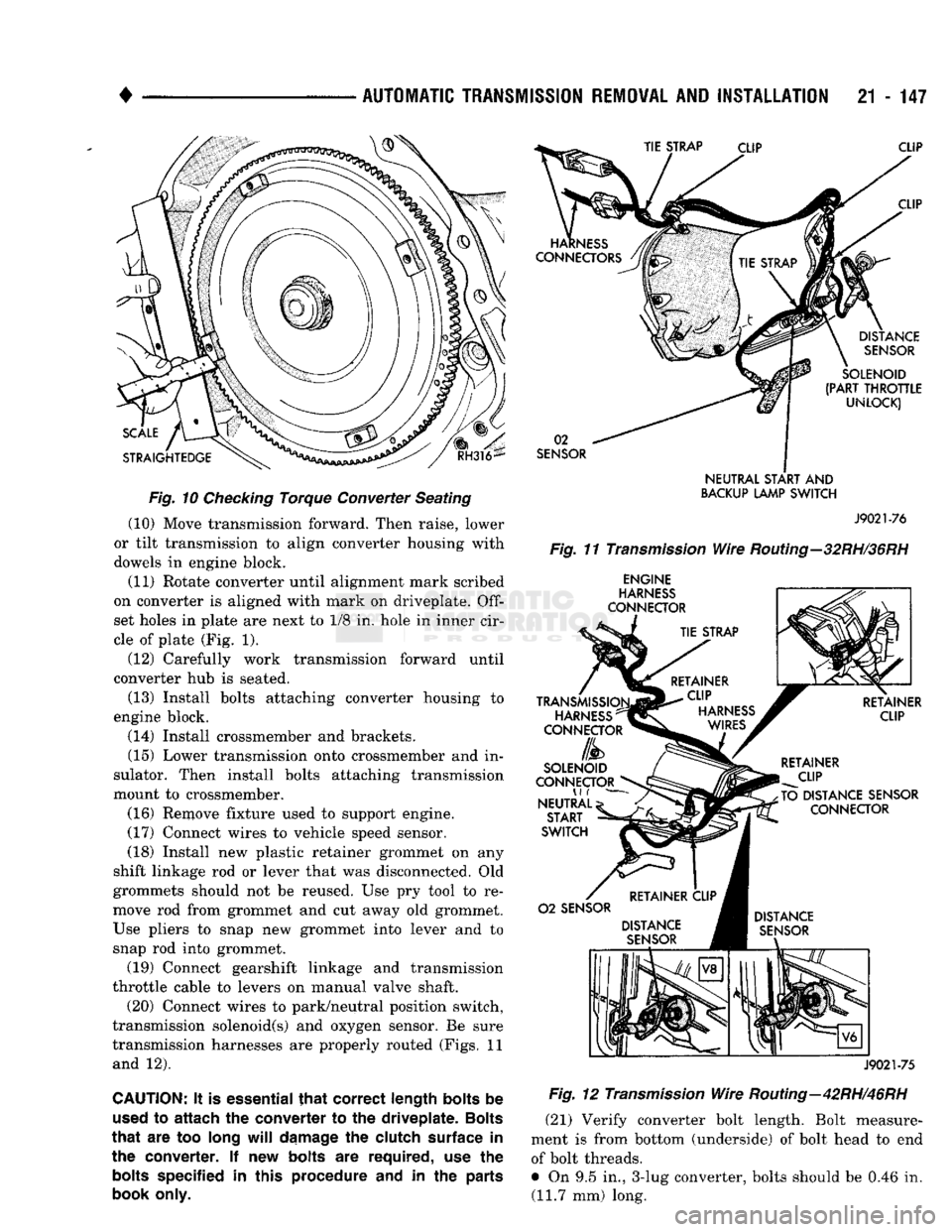
(5) Verify that converter is fully seated. Use
straight edge and steel ruler to check seating (Fig.
10).
Surface of converter lugs should be approxi
mately 13 mm (1/2 in.) to rear of straight edge when
converter is fully seated. (6) Temporarily secure converter with C-clamp at
tached to housing or with metal strap attached across converter housing. (7) Mount transmission on jack and secure it with
safety chains. (8) Check condition of converter driveplate. Re
place plate if cracked, distorted or damaged. If driveplate replacement was necessary, be sure
transmission dowel pins are seated in engine
block and protrude far enough to held transmis sion in alignment. (9) Raise transmission and align converter with
crankshaft and drive plate.
Page 1148 of 1502
•
AUTOMATIC TRANSMISSION REMOVAL
AND
INSTALLATION
21 - 147
Fig.
10 Checking Torque Converter Seating (10) Move transmission forward. Then raise, lower
or tilt transmission to align converter housing with
dowels in engine block.
(11) Rotate converter until alignment mark scribed
on converter is aligned with mark on driveplate.
Off
set holes in plate are next to 1/8 in. hole in inner cir
cle of plate (Fig. 1).
(12) Carefully work transmission forward until
converter hub is seated.
(13) Install bolts attaching converter housing to
engine block. (14) Install crossmember and brackets.
(15) Lower transmission onto crossmember and in
sulator. Then install bolts attaching transmission
mount to crossmember.
(16) Remove fixture used to support engine.
(17) Connect wires to vehicle speed sensor.
(18) Install new plastic retainer grommet on any
shift linkage rod or lever that was disconnected. Old
grommets should not be reused. Use pry tool to re
move rod from grommet and cut away old grommet.
Use pliers to snap new grommet into lever and to
snap rod into grommet.
(19) Connect gearshift linkage and transmission
throttle cable to levers on manual valve shaft.
(20) Connect wires to park/neutral position switch,
transmission solenoid(s) and oxygen sensor. Be sure
transmission harnesses are properly routed (Figs. 11 and 12).
CAUTION:
It is
essential
that
correct length bolts
be
used
to
attach
the
converter
to the
driveplate. Bolts
that
are too
long
will
damage
the
clutch surface
in the
converter.
If new
bolts
are
required,
use the
bolts
specified
in
this procedure
and in the
parts
book only.
SENSOR
NEUTRAL
START
AND
BACKUP
LAMP
SWITCH
J9021-76
Fig.
11
Transmission
Wire
Routing—32RH/36RH
ENGINE
J9021-75
Fig.
12
Transmission
Wire
Routing—42RH/46RH
(21) Verify converter bolt length. Bolt measure
ment is from bottom (underside) of bolt head to end of bolt threads.
• On 9.5 in., 3-lug converter, bolts should be 0.46 in. (11.7 mm) long.
Page 1150 of 1502
•
AUTOMATIC
TRANSMISSION
REMOVAL
AND
INSTALLATION
21 - 149
10).
Surface of converter lugs should be approxi
mately 13 mm (1/2 in.) to rear of straight edge when converter is fully seated.
(5) Temporarily secure converter in pump and
housing with C-clamp attached to housing edge, or
with metal strap attached across converter housing.
(6) Position transmission on jack. Secure transmis
sion to jack with safety chains.
(7) Check condition of converter driveplate. Re
place plate if cracked, distorted or damaged. If driveplate replacement was necessary, be sure
transmission dowel pins are seated in engine block and protrude far enough to held transmis sion in alignment.
(8) Coat pilot hub of torque converter with trans
mission fluid.
(9) Raise transmission and align converter with
drive plate and crankshaft.
(10) Move transmission forward. Then raise, lower
or tilt transmission to align converter housing with
dowels on engine block.
(11) Rotate converter to align marks scribed on
converter and driveplate. Offset holes in plate are
next to 1/8 in. hole in inner circle of plate (Fig. 1).
(12) Carefully work transmission forward and over
engine block dowels until converter hub is seated in crankshaft.
(13) Install bolts attaching converter housing to
engine.
(14) Install crossmember.
(15) Lower transmission onto crossmember and in
stall bolts attaching transmission and insulator to
crossmember (Figs. 4 and 5). (16) Remove fixture used to support engine.
(17) Connect vehicle speed sensor wires. (18) Install new plastic retainer grommet on any
shift linkage rod or lever that was disconnected. Old
grommets should not be reused. Use pry tool to re
move rod from grommet and cut away old grommet.
Use pliers to snap new grommet into lever and to snap rod into grommet. (19) Connect gearshift and throttle linkage to
transmission. (20) Connect wires to park/neutral position switch,
transmission solenoids and to oxygen sensor. Be sure
transmission harnesses are properly routed.
CAUTION:
It is essential
that
correct length
bolts
be
used
to
attach
the
converter
to the
driveplate.
Bolts
that
are too long
will
damage
the
clutch
surface
in
the converter. If new
bolts
are required, use the
bolts
specified in this procedure and in the parts
book
only.
(21) Verify converter bolt length. Bolt measure
ment is from bottom (underside) of bolt head to end
of bolt threads. • On 9.5 in., 3-lug converter, bolts should be 11.7
mm (0.46 in.) long.
• On 9.5 in., 4-lug converter, bolts should be 13.2
mm (0.52 in.) long.
• On 10.0 in., 4-lug converter, bolts should be 13.2
mm (0.52 in.) long.
• On 10.75 in., 4-lug converter, bolts should be 11.2
mm (0.44 in.) long.
(22) Install torque converter bolts. Tighten bolts as
follows:
• On models with 9.5 in., 3-lug converter, tighten
bolts to 54 Nnn (40 ft. lbs.).
• On models with 9.5 in., 4-lug converter, tighten
bolts to 74 Nnn (55 ft. lbs.).
• On models with 10.0 in., 4-lug converter, tighten
bolts to 74 Nnn (55 ft. lbs.) torque.
• On models with 10.75 in., 4-lug converter, tighten
bolts to 31 Nnn (270 in. lbs.).
• On diesel models with 12.2 in. converter, tighten
bolts to 47 Nnn (35 ft. lbs.) torque.
(23) Install converter housing access cover. (24) Install starter motor and cooler line bracket.
(25) Connect cooler lines to transmission.
(26) Install transmission fill tube. Install new
O-ring seal on tube before installation.
(27) Install any exhaust components removed for
service access. (28) Support transfer case on transmission jack.
Secure transfer case to jack with safety chains. (29) Install gasket on transmission adapter. Coat
gasket with Mopar perfect, seal, or silicone sealer be
forehand. (30) Install transfer case on transmission. Tighten
transfer case attaching nuts to 47 Nnn (35 ft. lbs.) torque. (31) Remove jack supporting transfer case.
(32) Connect transfer case shift lever to range le
ver. (33) Align and install propeller shafts. Tighten
clamp bolts to 19 Nnn 170 in. lbs.) torque. (34) Install transfer case skid plate and crossmem
ber. (35) Lower vehicle.
(36) Fill transmission with Mopar ATF Plus, Type
7176, or Mopar Dexron II if ATF Plus is not readily
available. (37) Check and adjust gearshift, throttle valve and
transfer case shift linkages if necessary.
OVERDRIVE
UNIT
REMOVAL—42RH/46RH
The following removal and installation procedures
apply to the 42RH/46RH overdrive unit only. If the
complete transmission assembly must be removed,
refer to the Transmission And Converter Removal and Installation procedures. (1) Shift transmission into Park.
(2) Raise vehicle.
Page 1343 of 1502
21
- 342
NP205 TRANSFER CASE
•
NP205
TRANSFER CASE
INDEX
page
General
Information
342
Recommended Lubricants
342
Service Diagnosis
342
Shift
Linkage
Adjustment
344
Speedometer Service
345
GENERAL
INFORMATION
The NP205 transfer case
is a
heavy duty, part-time
unit with constant mesh, helical gears.
The
gears
are
mounted
in a
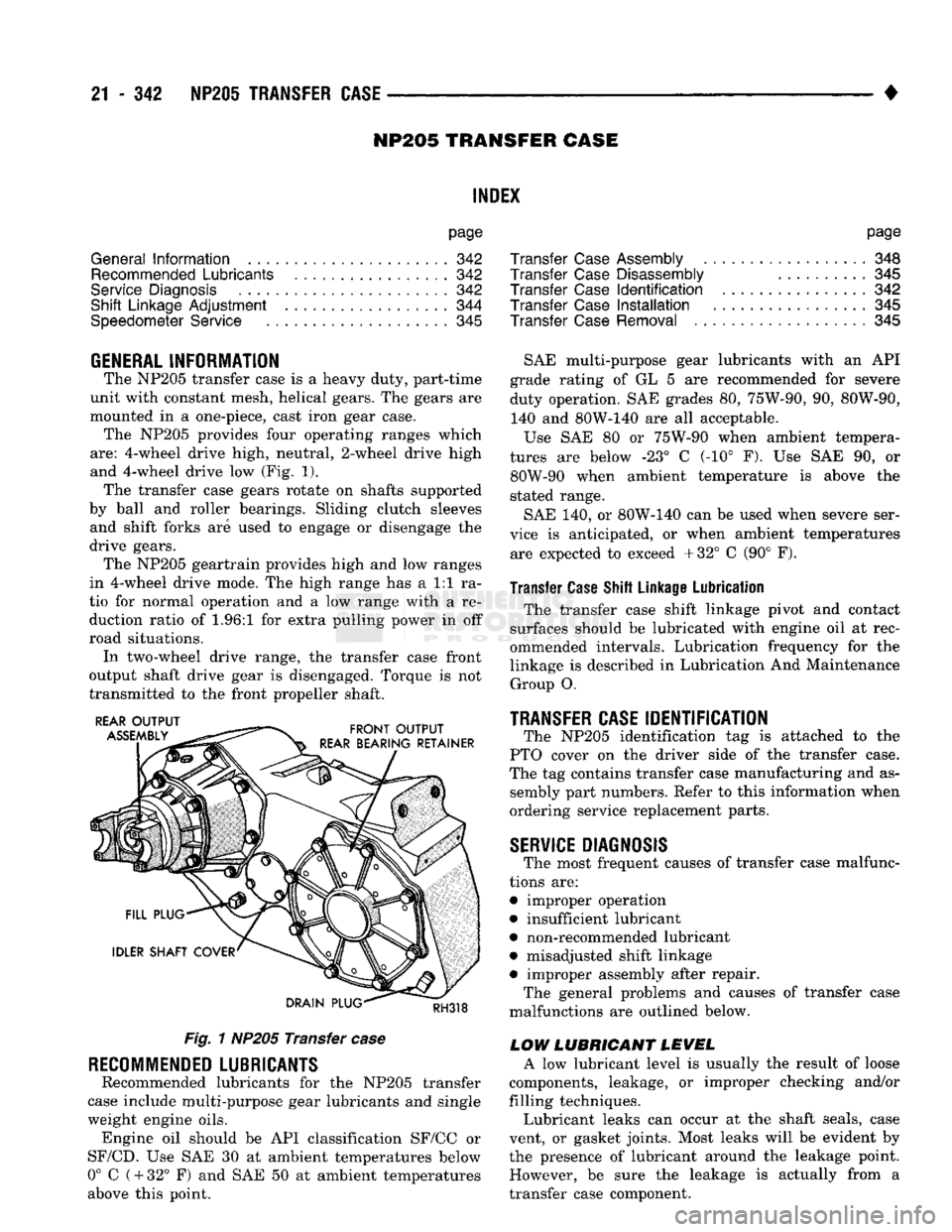
one-piece, cast iron gear case. The NP205 provides four operating ranges which
are:
4-wheel drive high, neutral, 2-wheel drive high
and 4-wheel drive
low (Fig. 1).
The transfer case gears rotate
on
shafts supported
by ball
and
roller bearings. Sliding clutch sleeves and shift forks
are
used
to
engage
or
disengage
the
drive gears. The NP205 geartrain provides high
and low
ranges
in 4-wheel drive mode.
The
high range
has a 1:1 ra
tio
for
normal operation
and a low
range with
a re
duction ratio
of 1.96:1 for
extra pulling power
in off
road situations. In two-wheel drive range,
the
transfer case front
output shaft drive gear
is
disengaged. Torque
is not
transmitted
to the
front propeller shaft.
Fig.
1
NP205 Transfer
case
RECOMMENDED
LUBRICANTS
Recommended lubricants
for the
NP205 transfer
case include multi-purpose gear lubricants
and
single
weight engine oils. Engine
oil
should
be API
classification SF/CC
or
SF/CD.
Use SAE 30 at
ambient temperatures below
0°
C
(
+
32°
F) and SAE 50 at
ambient temperatures
above this point.
page
Transfer
Case
Assembly
348
Transfer
Case
Disassembly
..........
345
Transfer
Case
Identification
342
Transfer
Case
Installation
345
Transfer
Case
Removal
345
SAE multi-purpose gear lubricants with
an API
grade rating
of GL 5 are
recommended
for
severe
duty operation.
SAE
grades
80,
75W-90,
90,
80W-90, 140
and
80W-140
are all
acceptable.
Use
SAE 80 or
75W-90 when ambient tempera
tures
are
below
-23° C (-10° F). Use SAE 90, or
80W-90 when ambient temperature
is
above
the
stated range.
SAE
140, or
80W-140
can be
used when severe ser
vice
is
anticipated,
or
when ambient temperatures are expected
to
exceed +32°
C (90° F).
Transfer Case Shift Linkage Lubrication
The transfer case shift linkage pivot
and
contact
surfaces should
be
lubricated with engine
oil at
rec
ommended intervals. Lubrication frequency
for the
linkage
is
described
in
Lubrication
And
Maintenance Group
O.
TRANSFER CASE
IDENTIFICATION
The NP205 identification
tag is
attached
to the
PTO cover
on the
driver side
of the
transfer case.
The
tag
contains transfer case manufacturing
and as
sembly part numbers. Refer
to
this information when
ordering service replacement parts.
SERVICE
DIAGNOSIS
The most frequent causes
of
transfer case malfunc
tions
are:
• improper operation
• insufficient lubricant
• non-recommended lubricant
• misadjusted shift linkage
• improper assembly after repair. The general problems
and
causes
of
transfer case
malfunctions
are
outlined below.
LOW LUBRICANT LEVEL
A
low
lubricant level
is
usually
the
result
of
loose
components, leakage,
or
improper checking and/or
filling techniques. Lubricant leaks
can
occur
at the
shaft seals, case
vent,
or
gasket joints. Most leaks will
be
evident
by
the presence
of
lubricant around
the
leakage point. However,
be
sure
the
leakage
is
actually from
a
transfer case component.