1993 DODGE TRUCK jump start
[x] Cancel search: jump startPage 387 of 1502
8E
- 6
INSTRUMENT PANEL
AND
GAUGES
•
(5)
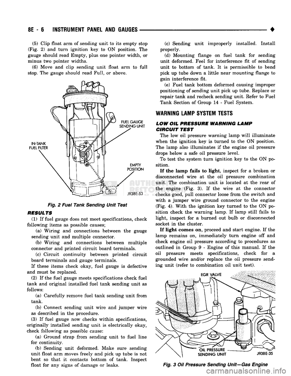
Clip float arm of sending unit to its empty stop
(Fig. 2) and turn ignition key to ON position. The
gauge should read Empty, plus one pointer width, or
minus two pointer widths.
(6) Move and clip sending unit float arm to full
stop.
The gauge should read Full, or above.
Fig. 2 Fuel Tank Sending Unit Test
RESULTS (1) If fuel gauge does not meet specifications, check
following items as possible causes; (a) Wiring and connections between the gauge
sending unit and multiple connector. (b) Wiring and connections between multiple
connector and printed circuit board terminals.
(c) Circuit continuity between printed circuit
board terminals and gauge terminals.
If these items check okay, fuel gauge is defective
and must be replaced.
(2) If the fuel gauge meets specifications check fuel
tank and original installed fuel tank sending unit as follows:
(a) Carefully remove fuel tank sending unit from
tank.
(b) Connect sending unit wire and jumper wire
as described in the procedure.
(3) If fuel gauge now checks within specifications,
originally installed sending unit is electrically okay,
check following as possible cause:
(a) Ground strap from sending unit to fuel line
for continuity. (b) Sending unit deformed. Make sure sending
unit float arm moves freely and pick up tube is not
bent so that it contacts bottom of tank. Inspect float for any signs of damage or leaks. (c) Sending unit improperly installed. Install
properly.
(d) Mounting flange on fuel tank for sending
unit deformed. Feel for interference fit of sending
unit to bottom of tank. It is permissible to bend
pick up tube down a little near mounting flange to gain interference fit.
(e) Fuel tank bottom deformed causing improper
positioning of sending unit pick up tube. Replace or
repair tank and recheck sending unit. Refer to Fuel
Tank Section of Group 14 - Fuel System.
WARNING
LAMP
SYSTEM
TESTS
LOW
OH.
PRESSURE WARNING LAMP CIRCUIT
TEST
The low oil pressure warning lamp will illuminate
when the ignition key is turned to the ON position.
The lamp also illuminates if the engine oil pressure drops below a safe oil pressure level.
To test the system turn ignition key to the ON po
sition.
If the lamp fails to light, inspect for a broken or
disconnected wire at the oil pressure combination
unit. The combination unit is located at the rear of
the engine (Fig. 3). If the wire at the connector checks good, pull connector loose from the switch and
with a jumper wire ground connector to the engine (Fig. 4). With the ignition key turned to the ON po
sition check the warning lamp. If lamp still fails to
light, inspect for a burned out bulb or disconnected
socket in the cluster.
If light comes on, proceed and start engine. If the
lamp remains on, immediately turn engine off and
check engine oil pressure according to procedures as
outlined in Group 9 - Engine of this manual. If the
oil pressure meets specifications, check for a
grounded wire and/or replace the oil pressure send
ing unit (refer to combination oil unit test). Fig. 3 Oil Pressure Sending Unit—Gas Engine
Page 512 of 1502
WIRING
DIAGRAMS
8W
- 37
WIRING DIAGRAMS AD-BODY
INDEX
Wiring Diagram Name Sheet Number
A/C
Heater System
with
Diesel Engine ............ .69,70 Blower Motor
. .69
Compressor
.70
Cycling Switch
.70
Diodes
70
Fuse
69
Low Pressure Switch
70
Resistor
. 69
Switch-Blower
. 69
Vacuum
Control
Switch
.69
Wide Open
Throttle
Cut-Out Relay
70
A/C
Heater System
with Gas
Engine .67,68 Blower Motor
.67
Compressor
.68
Cycling Switch
68
Low Pressure Switch
.68
Diodes
. .68
Fuse
. .67
Resistor
67
Switch-Blower
67
Vacuum
Control
Switch
.67
Wide Open
Throttle
Cutout Relay
68
Air Heater Relay Diesel Engine
.21
Air
Intake
Heater Diesel Engine
22
Anti-Lock Rear Brake System
with
Diesel Engine
.....
.33,34 Brake Warning Lamp Switch
34
Data Link Connector
33
Duel Solenoid Hydraulic Valve
34
Electronic Vacuum
Sensor
.34
Fuse
33
Module
.33
Park
Brake Switch
.33
Resistor
34
Rolls
Test Connector
33
Sensor
34
Stop
Lamp
34
Anti-Lock Rear Brake System
with Gas
Engine .31,32 Brake Warning Lamp Switch
.32
Data Link Connector
. .31
Dual Solenoid Hydraulic Valve
32
Fuse
31
Module
31
Park
Brake Switch
.31
Resistor
32
Rolls
Test Connector
31
Sensor
32
Stop
Lamp Switch
32
Back-Up
Lamp Switch
with
Diesel Engine
.7
Back-Up
Lamp Switch
with Gas
Engine
.9
Battery
.1,3,5
Brake Warning
Indicator
Lamp (Diesel Engine)
.57
Brake Warning
Indicator
Lamp
(Gas
Engine)
58
Brake Warning
Indicator
Lamp Switch (Diesel Engine)
. . . .34
Wiring Diagram Name Sheet Number
Brake Warning
Indicator
Lamp Switch
(Gas
Engine)
32
Bulkhead Disconnect 50-Way .85,86
Buzzer-Combined Headlamp,
Key In, and
Seat
Belt
. . .
.27,28
Bypass
Jumper
(Clutch
Pedal Position)
8
Cargo
Lamp .49,50
Cargo
Lamp Switch
49
Charging System
with
Diesel Engine ..............
.5,6
Battery
5
Generator
. .6
Charging System
with
Gas Engine
.3,4
Battery
3
Generator
, . .4
Cigar
Lighter,
Ash &
Glove
Box
Lamps
52
Circuit
Breakers Power Windows
2,71
Clearance Lamps Duel Rear Wheels
.
.41,43 Clearance Lamps Roof Mounted
40
Clockspring 30,36,38
Clutch Pedal Position Switch
.8
Cold
Start
Advance Motor
24
Compressor,
A/C
68,70 Data Link Connector 17,23,31,33
Data Link Connectors
Rear
Wheel Anti-Lock Diesel Engine
.33
Rear
Wheel Anti-Lock Gas Engine
31
Daytime Running
Light
Module
46
Diesel
Control
System .21,22,23,24,25,26
Air Heater Relay
. .21
Air
Intake
Heater
21
Automatic
Shut Down Relay
22
Cold
Start
24
Crankshaft Position
Sensor
. .25
Data Link Connector
. .23
Engine
Coolant Temp Switch
.26
Fuel Heater
24
Fuel Solenoid
24
Intake
Air
Temp
Sensor
25
Powertrain
Control
Module 21,22,23,25,26
Resistor
.24
Thermo Switch
24
Throttle
Position (Sensor)
26
Transmission Thermo Switch
. . .26
Vehicle Speed
Sensor
25,26 Water
in
Fuel
Sensor
.25
Dimmer Switch-Headlamp
. .47
Diode 68,70
Diode
and
Mold Assembly
51
Dome
and
Cargo Lamp
50
Door
Jamb Switches
49
Left
Switch
.49
Right Switch
49
Dual Solenoid Hydraulic Valve
.32
EMCC
System (3-Speed)
. .11
Page 513 of 1502
8W
- 38
WIRING
DIAGRAMS
• Wiring Diagram Name Sheet Number
EMCC
Relay
11
EMCC
Solenoid
11
Ground
11
EMCC
Relay
with Gas
Engine
11,16
EMCC
Solenoid
with Gas
Engine
11,12
Engine
Oil
Pressure Sending
Unit
.27,28
Engine
Starter
Motor
7,9
Engine
Starter
Relay
.7,9
Engine
Starter
System 1,7,8,9 Back-Up Lamp
Switch
.7,9
Bypass
Jumper
(Clutch
Pedal
Position)
8
Clutch
Pedal
Position
Switch
8
Fuse
. 7,9
Motor
7,9
Park/Neutral
Position
Switch
. .7,9
Relay
7,9
Engine Temp Sending
Unit
.
.27,28
Flasher-Hazard Warning
.56
Flasher-Turn Signal
56
Four Wheel
Drive
Indicator
Lamp
13
Front
End
Lighting
. .
.43,44
Front
End
Lighting
(Canada) 45,46
Fuel
Gauge
81,82
Fuel
Tank Gauge
Level
Sending
Unit
Diesel Engine
77
Fuel
Tank Gauge
Level
Sending
Unit
with Gas
Engine
78
Fuel
Heater
Diesel Engine
24
Fuel
Solenoid Diesel Engine
.24
Fuse
Application
Chart
1,2
Fuse
Block Module
and
Relay Bank
82
Fuses
Fuse
1 2,36
Fuse
2
.........
2,10,12,13,14,58,77,78
Fuse
3
2,7,9,10,39
Fuse
4
1,30,47
Fuse
5
1,77,78
Fuse
6
......
.1,73
Fuse
7
1,10,52
Fuse
8
.2,10,61,63
Fuse
9
.2,10,31,33,56
Fuse
10
.2,10,54,55
Fuse
11
2,10,66,67,69
Fuse
12
2,10,71
Fuse
13 1,56
Fuse
14
1,47,52,61,63
Fuse
15
1,49,51,52,61,63,75
Fusible Links 1,2,3,4,5,6,21
Gas
Engine
Wiring
Connector
89
Gauge-Fuel .77,78
Generator
.4,6
Glove
Box
Lamp
Switch
52
Hazard Warning System
. .56
Headlamp Dimmer
Switch
47
Headlamp
Switch
1,47
Headlamp
Switch
Controlled
Interior
Lamps
Headlamps 43,44,
Heated
Rear Window
(Sport
Utility)
Heater
Motor
Resistor
Heater
System Wiring Diagram Name Sheet Number
Horn System
30
Identification
Lamps-Dual Rear Wheels
41,42
Identification
Lamps-Roof Mounted
. 40
Ignition
Coil
.16
Ignition
Switch
.2,10
Ignition
Switch
System
10
Ignition
System (Gas Engine)
.........
.15,16,17,18,19,20
Automatic
Shut Down Relay
.16
Camshaft
Position
Sensor
20
Crankshaft
Position
Sensor
.18
Data
Link
Connector
* . . .17
Engine Coolant Temp
Sensor
20
EVAP
Purge Solenoid
16
Exhaust Gas
Recirculation
Solenoid
16
Fuel
Pump Relay
.16
Heated
Oxygen
Sensor
. . . 17
Idle
Air
Control
Motor
.19
Ignition
Coil
.15
Injectors
.15
Intake
Air
Temp
Sensor
. .20
Map
Sensor
. .20
Powertrain
Control
Module .15,16,17,18,19,20
Throttle
Position
(Sensor)
.18
Vehicle
Speed
Sensor
.20
Ignition
Time
Delay Relay
49
Injectors
.15 Intermittent
Wiper
System .53,54
Control
Unit
.54 Intermittent
Windshield
Wiper
Motor
54
Windshield
Washer Pump
Motor
53
Wiper
Switch
53
Key-In
Switch
49
Key-In Warning Buzzer 77,78
Lamps
Air-Conditioning
and
Heater
Switch
Lamp
48
Ash
Receiver .48,52 Back-Up Lamps
......
79,80,81
Cargo Lamp
.
.49,50 Clearance Lamps-Dual Rear Wheels .41,42
Clearance Lamps Roof Mounted
.40
Cluster
Illumination
Lamps
.
.57,58,59
Dome Lamp
50,51
Four Wheel
Drive
Indicator
.13
Glove
Box
Lamp
52
Headlamp-Left
43,45 Headlamp-Right 44,46
Headlamp
Switch
Controlled
Interior
Lamps
. 48
Heater
Switch
Lamp
.48
High Beam
Indicator
Lamp
.59
Identification
Lamp
.
.40,41
Ignition
Switch
Lamp
.49
Instrument
Panel
Illumination
Lamps
.
.57,58,59
License Lamp
. . . 80
.
.48 Low
Engine
Oil
Pressure Lamp
59
45,46
Map
Lamp
49
.
.39
Parking
Lamp-Left
Front
43,45
66,67 Parking Lamp-Right
Front
44,46 .
.66
Rear
End
Lighting
System .79,80,81
Page 524 of 1502
WIRING DIAGRAMS 8W - 49
TO
IGNITION
SWITCH
(SEE
SH 10) • A41 16YL—»-
S21
14YL/BK
31
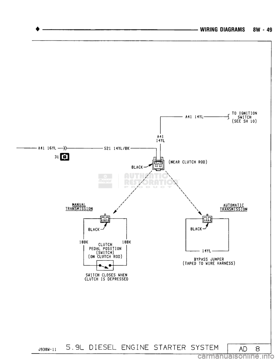
MANUAL
TRANSMISSION
BLACK J
18BK
CLUKH
18BK
PEDAL POSITION
(SWITCH)
(ON CLUTCH ROD)
BYPASS
JUMPER
(TAPED TO WIRE HARNESS)
SWITCH CLOSES WHEN
CLUTCH IS
DEPRESSED
J938W-11
5.9L DIESEL ENGINE STARTER SYSTEM
AD 8
Page 875 of 1502
14
- 56
FUEL
SYSTEM
• (5) Move the switch to the HIGH position. The en
gine speed should increase. Move the switch to the
LOW position. The engine speed should decrease.
(a) If the engine speed changes while using the
exerciser tool, the IAC motor is functioning prop
erly. Disconnect the exerciser tool and connect the
IAC stepper motor wire connector to the stepper motor.
(b) If the engine speed does not change, turn the
ignition OFF and proceed to step (6). Do not discon
nect exerciser from the IAC stepper motor.
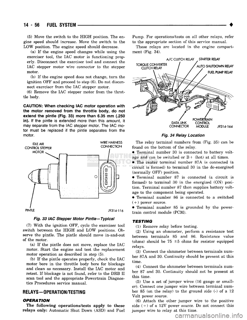
(6) Remove the IAC stepper motor from the throt
tle body.
CAUTION:
When checking IAC motor operation with
the motor removed from
the
throttle
body,
do not
extend
the
pintle (Fig.
33)
more than
6.35 mm (.250
in).
If the pintle is
extended more than
this
amount,
it
may
separate
from
the
IAC stepper
motor.
The
IAC
mo
tor
must
be
replaced
if the pintle
separates
from
the
motor.
WIRE HARNESS
PINTLE
J9314-116
Fig.
33 IAC Stepper Motor Pintle—Typical (7) With the ignition OFF, cycle the exerciser tool
switch between the HIGH and LOW positions. Ob
serve the pintle. The pintle should move in-and-out
of the motor.
(a) If the pintle does not move, replace the IAC
motor. Start the engine and test the replacement
motor operation as described in step (5). (b) If the pintle operates properly, check the IAC
motor bore in the throttle body bore for blockage and clean as necessary. Install the IAC motor and
retest. If blockage is not found, refer to the DRB II scan tool and the appropriate Powertrain Diagnos
tics Procedures service manual.
RELAYS—OPERATION/TESTING
OPERATION
The following operations/tests apply to these
relays only: Automatic Shut Down (ASD) and Fuel Pump. For operations/tests on all other relays, refer
to the appropriate section of this service manual.
These relays are located in the engine compart
ment (Fig. 34).
DATA LINK CONTROL
CONNECTOR MODULE
J9314-164
Fig.
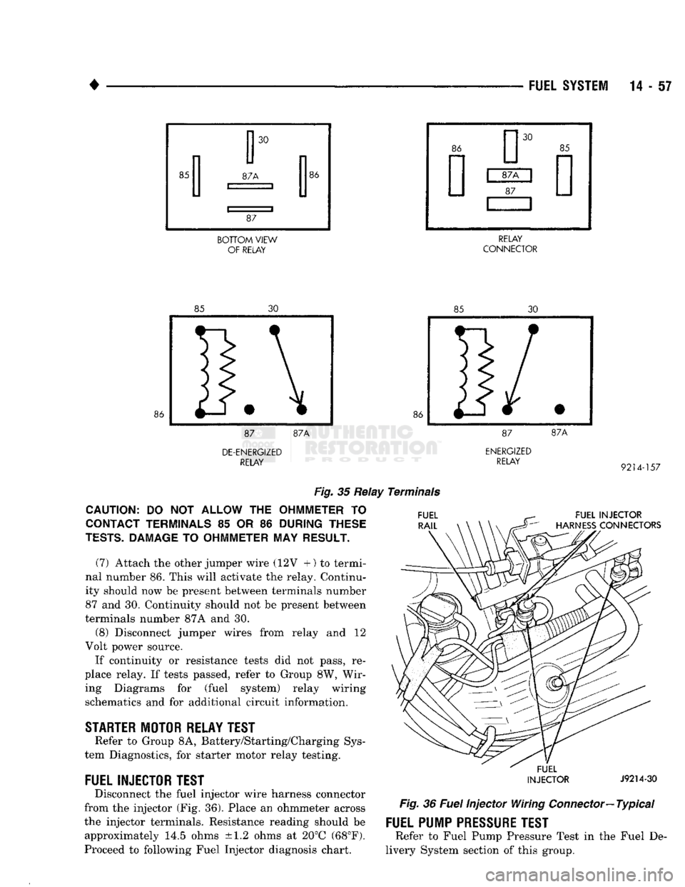
34 Relay Location The relay terminal numbers from (Fig. 35) can be
found on the bottom of the relay. • Terminal number 30 is connected to battery volt
age and can be switched or B+ (hot) at all times.
• The center terminal number 87A is connected (a
circuit is formed) to terminal 30 in the de-energized (normally OFF) position.
• Terminal number 87 is connected (a circuit is
formed) to terminal 30 in the energized (ON) posi
tion. Terminal number 87 then supplies battery volt age to the component being operated.
• Terminal number 86 is connected to a switched ( +
)
power source.
• Terminal number 85 is grounded by the power-
train control module (PCM).
TESTING
(1) Remove relay before testing. (2) Using an ohmmeter, perform a resistance test
between terminals 85 and 86. Resistance value (ohms) should be 75 ±5 ohms for resistor equipped
relays.
(3) Connect the ohmmeter between terminals num
ber 87A and 30. Continuity should be present at this
time.
(4) Connect the ohmmeter between terminals num
ber 87 and 30. Continuity should not be present at
this time.
(5) Use a set of jumper wires (16 gauge or small
er).
Connect one jumper wire between terminal num
ber 85 (on the relay) to the ground side (-) of a 12 Volt power source. (6) Attach the other jumper wire to the positive
side ( +
)
of a 12V power source. Do not connect this
jumper wire to relay at this time.
Page 876 of 1502
•
BOTTOM
VIEW
OF RELAY RELAY
CONNECTOR
DE-ENERGIZED
RELAY
ENERGIZED
RELAY
9214-157
Fig.
35 Relay Terminals
CAUTION:
DO NOT
ALLOW
THE
OHMMETER
TO
CONTACT TERMINALS
85 OR 86
DURING THESE
TESTS.
DAMAGE
TO
OHMMETER
MAY
RESULT.
(7) Attach the other jumper wire (12V +) to termi
nal number 86. This will activate the relay. Continu
ity should now be present between terminals number
87 and 30. Continuity should not be present between
terminals number 87A and 30.
(8) Disconnect jumper wires from relay and 12
Volt power source.
If continuity or resistance tests did not pass, re
place relay. If tests passed, refer to Group 8W, Wir ing Diagrams for (fuel system) relay wiring schematics and for additional circuit information.
STARTER
MOTOR RELAY TEST
Refer to Group 8A, Battery/Starting/Charging Sys
tem Diagnostics, for starter motor relay testing.
FUEL INJECTOR TEST
Disconnect the fuel injector wire harness connector
from the injector (Fig. 36). Place an ohmmeter across
the injector terminals. Resistance reading should be approximately 14.5 ohms ±1.2 ohms at 20°C (68°F).
Proceed to following Fuel Injector diagnosis chart.
FUEL INJECTOR
HARNESS
CONNECTORS
FUEL
INJECTOR
J9214-30
Fig.
36
Fuel
Injector Wiring
Connector—
Typical
FUEL PUMP
PRESSURE
TEST
Refer to Fuel Pump Pressure Test in the Fuel De
livery System section of this group.
Page 1448 of 1502
HEATING
AND
AIR
CONDITIONING
24 -
TEMPERATURE
IN
TEST AREA
21-29° C
(70-85°
F)
VERIFY R-12 CHARGE-CONNECT MANIFOLD GAUGES
SEE
MAINTENANCE AND ADJUSTMENTS SECTION
IF
R-12
CHARGE
IS
LOW, CORRECT LEAK, EVACUATE, AND CHARGE SYSTEM
BYPASS
CYCLING CLUTCH SWITCH USING JUMPER WIRE REFER
TO
GROUP
8W,
WIRING DIAGRAMS
START ENGINE ADJUST IDLE
TO 1000
rpm
IN
PARK OR NEUTRAL
WITH
PARK BRAKE SET LOCATE AND REMOVE BOTH
VACUUM LINES AT RECIRC DOOR ACTUATOR INSTALL
LT-GN LINE WHERE DK-GN LINE HAD BEEN
CLOSE
PASSENGER COMPARTMENT
SET
CONTROL TO A/C, PANEL, HIGH BLOWER, FULL HEAT
ENGINE
RPM BLOWER
MOTOR
SPEED
I
EVAPORATOR
I
SUCTION GAUGE
I
PSIG
(kPag)
1
COMPRESSOR
DISCHARGE
GAUGE
PSIG
(kPag)
2
—m
POSSIBLE
I
CAUSE
I
20-35
PSIG
140-240
PSIG
1000 —
HI
(140 TO 240
kPag)
(966
TO
1656
kPag)
i
— NORMAL
Cr a
FREEZE
H-VALVE 15 INCHES
OF VACUUM
THAW
H-VALVE 38 PSIG
(262
kPag)
OR MORE THEN
DROPS
TO 25 TO 35
PSIG
(172
TO
240
kPag)
RETURN RECIRC DOOR VACUUM LINES
TO
NORMAL a
1000
HI
20 30
PSIG
(140 TO 207
kPag)
H240
PSIG OR HIGHER
(1656
kPag)
20-30
PSIG
(140-207
kPag)
140
PSIG
(966
kPag)
OR
LESS
H-VALVE
STUCK OPEN
IF
CONDITIONS
CANNOT BE MET
H-VALVE
STUCK CLOSED
IF
CONDITIONS
CANNOT BE MET
RESTRICTED
CONDENSER-
RESTRICTED
DISCHARGE
LINE
-RADIATOR
OVERHEATING-
AIR
IN
SYSTEM- OVERCHARGED
SYSTEM-COOLING FAN INOP.
RECONNECT LOW PRESSURE/CYCLING SWITCH AND RECONNECT THE VACUUM LINES
TO
THE RECIRC/ACUATOR DEFECTIVE
COMPRESSOR
HEAD
GASKET
OR
DISCHARGE
REEDS
J9124-104
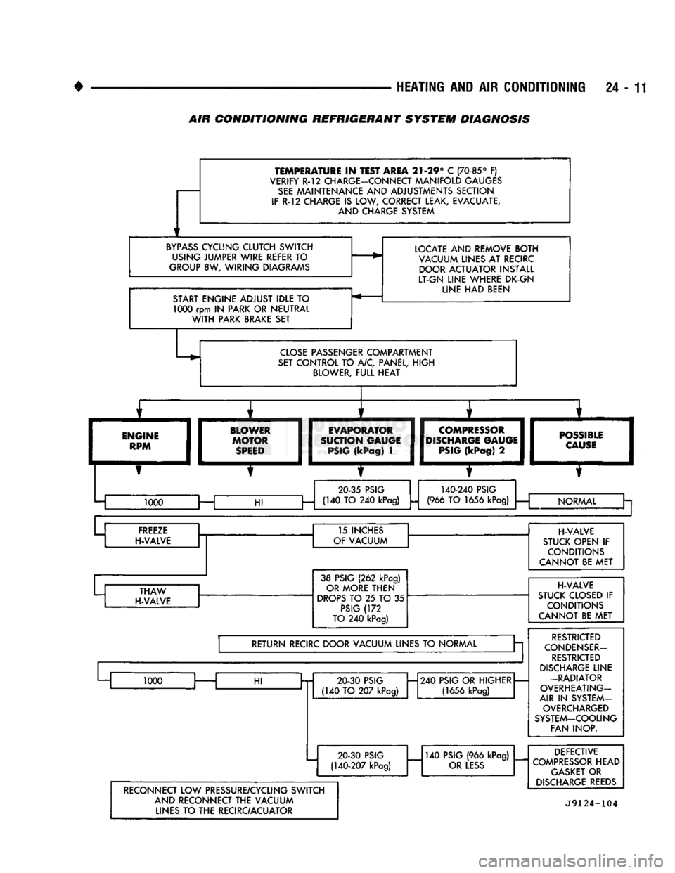
AIR
CONDITIONING REFRIGERANT SYSTEM DIAGNOSIS