1991 MITSUBISHI ECLIPSE wiring
[x] Cancel search: wiringPage 1139 of 1216
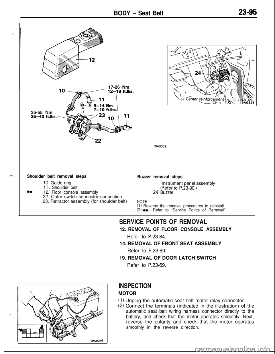
BODY - Seat Belt23-9535-55 Nm
25-40 ft.lbs.\17-26 Nm
Shoulder belt removal steps
10. Guide ring
1 1. Shoulder beltc*12. Floor console assembly22. Outer switch connector connection
23. Retractor assembly (for shoulder belt)
19A0309
Buzzer removal stepsInstrument panel assembly24
(gy;ZfieerrtO P.23-80.)
NOTE(1) Reverse the removal procedures to reinstall.(2) +e : Refer to “Service Points of Removal”
19A0319
SERVICE POINTS OF REMOVAL
12. REMOVAL OF FLOOR CONSOLE ASSEMBLYRefer to
P.23-84.14. REMOVAL OF FRONT SEAT ASSEMBLY
Refer to
P.23-90.19. REMOVAL OF DOOR LATCH SWITCH
Refer to
P.23-69.
INSPECTION
MOTOR
(1) Unplug the automatic seat belt motor relay connector.
(2) Connect the terminals (indicated in the illustration) of the
automatic seat belt wiring harness connector directly to the
battery, and check that the motor operates smoothly. Next,reverse the polarity and check that the motor operates
smoothly in the reverse direction.
Page 1140 of 1216
23-96BODY - Seat Belt
Q ET19A0316
I) : Terminal to checkthe release switch
I+ : Terminal to check
the fasten switchlQA0316
16A07.51
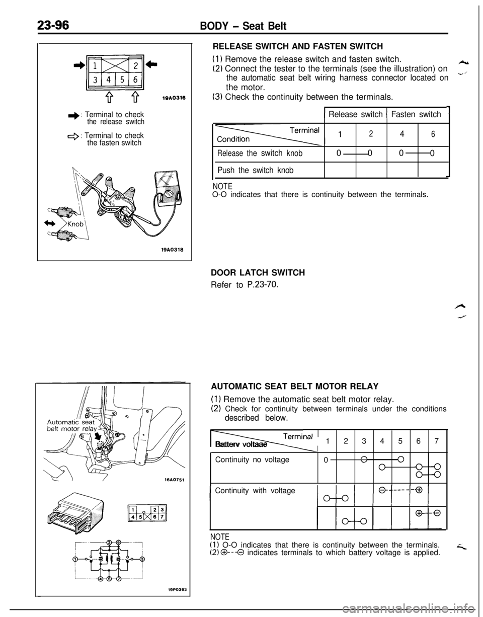
19PO363RELEASE SWITCH AND FASTEN SWITCH
(1) Remove the release switch and fasten switch.
(2) Connect the tester to the terminals (see the illustration) on*
the automatic seat belt wiring harness connector located on-’the motor.
(3) Check the continuity between the terminals.
11 Release switch 1 Fasten switch
Releasetheswitchknob
Push the switch knob
246000
0
NOTEO-O indicates that there is continuity between the terminals.
DOOR LATCH SWITCH
Refer to
P.23-70.AUTOMATIC SEAT BELT MOTOR RELAY
(1) Remove the automatic seat belt motor relay.
(2) Check for continuity between terminals under the conditions
described below.
Termi, lalIIBatterv voltaae
m-al1234567
Continuity no voltage
0
n 0”0
IContinuity with voltageIIIIIIII
NOTE(1) O-O indicates that there is continuity between the terminals.(2) O---O indicates terminals to which battery voltage is applied.
Page 1158 of 1216
24-14 HEATERS AND AIR CONDITIONING - Service Adjustment Procedures
-Discharge
w-w
SuctiongaugeDischalgauge
2OUO306
SuctiongaugeDischargegauge
2OUO307--
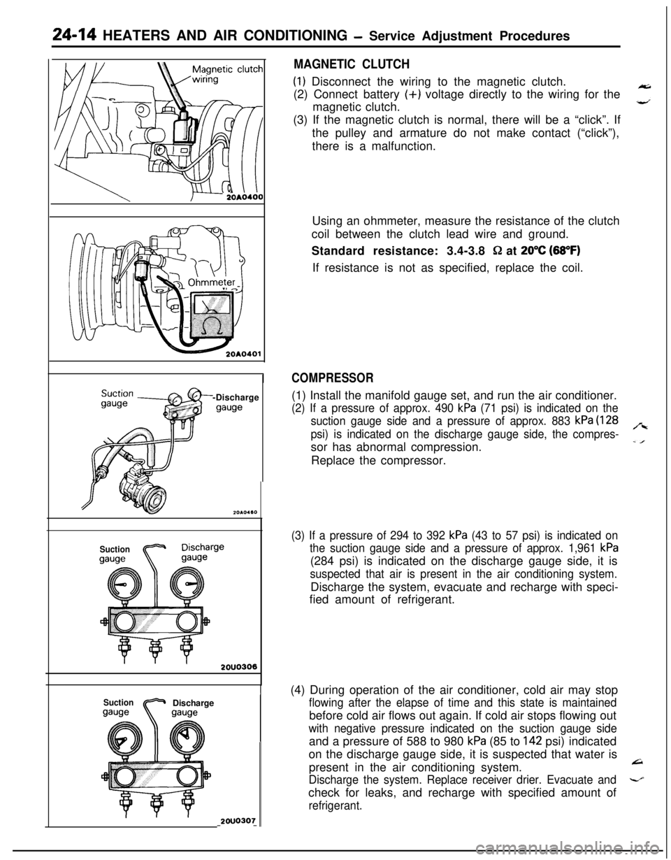
MAGNETIC CLUTCH(I) Disconnect the wiring to the magnetic clutch.
(2) Connect battery (+) voltage directly to the wiring for the
magnetic clutch.
,”(3) If the magnetic clutch is normal, there will be a “click”. If
the pulley and armature do not make contact (“click”),
there is a malfunction.
Using an ohmmeter, measure the resistance of the clutch
coil between the clutch lead wire and ground.
Standard resistance: 3.4-3.8
Q at 20°C (88°F)If resistance is not as specified, replace the coil.
COMPRESSOR(1) Install the manifold gauge set, and run the air conditioner.
(2) If a pressure of approx. 490 kPa (71 psi) is indicated on the
suction gauge side and a pressure of approx. 883
kPa (128
psi) is indicated on the discharge gauge side, the compres-
,“ssor has abnormal compression.
-IReplace the compressor.
(3) If a pressure of 294 to 392 kPa (43 to 57 psi) is indicated on
the suction gauge side and a pressure of approx. 1,961
kPa(284 psi) is indicated on the discharge gauge side, it is
suspected that air is present in the air conditioning system.Discharge the system, evacuate and recharge with speci-
fied amount of refrigerant.
(4) During operation of the air conditioner, cold air may stop
flowing after the elapse of time and this state is maintainedbefore cold air flows out again. If cold air stops flowing out
with negative pressure indicated on the suction gauge sideand a pressure of 588 to 980
kPa (85 to 142 psi) indicated
on the discharge gauge side, it is suspected that water is
present in the air conditioning system.
L=I
Discharge the system. Replace receiver drier. Evacuate and-check for leaks, and recharge with specified amount of
refrigerant.
Page 1162 of 1216
24-18 HEATERS AND AIR CONDITIONING - Service Adjustment Procedures
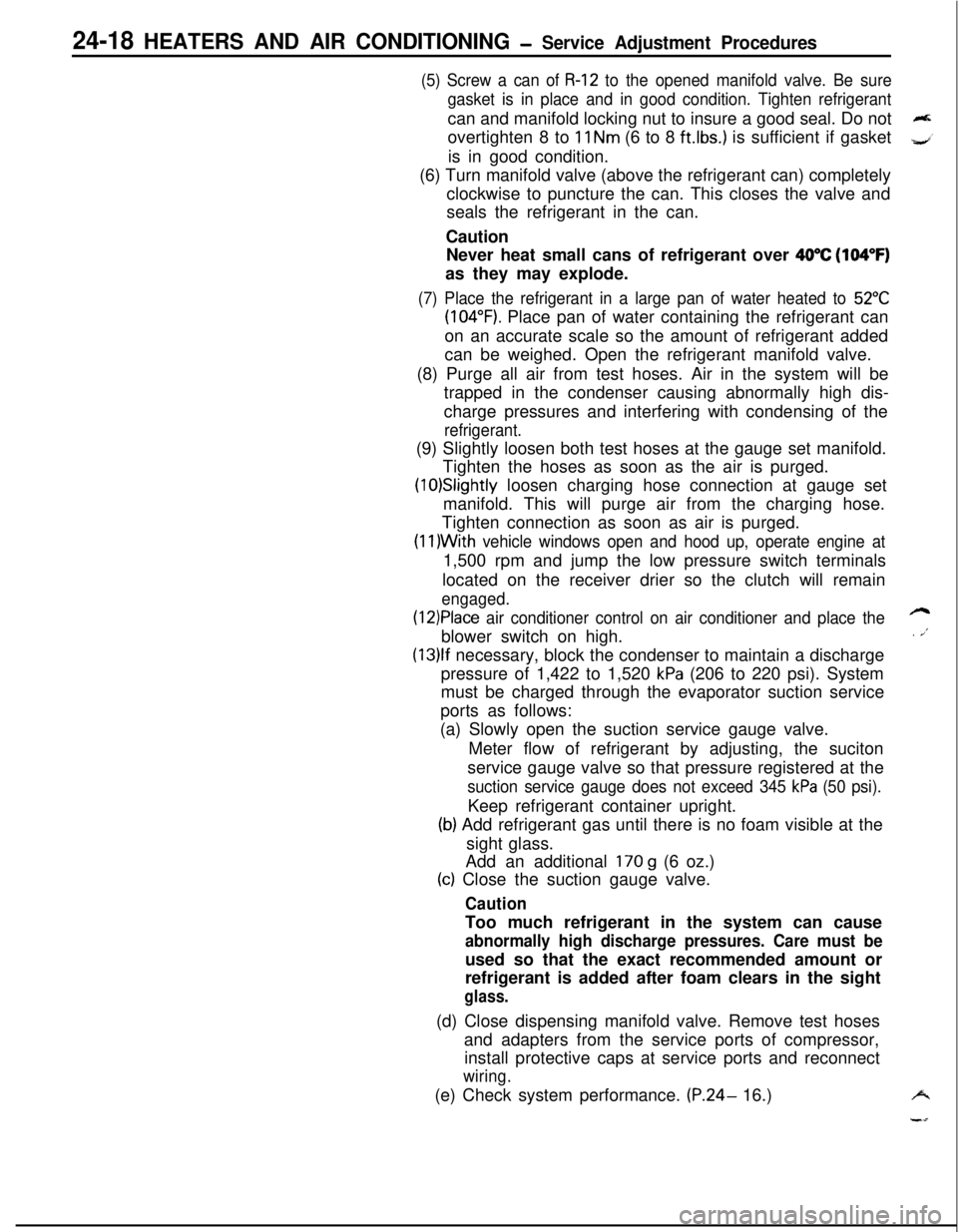
(5) Screw a can of R-12 to the opened manifold valve. Be sure
gasket is in place and in good condition. Tighten refrigerantcan and manifold locking nut to insure a good seal. Do not
overtighten 8 to
11 Nm (6 to 8 ft.lbs.) is sufficient if gasket
is in good condition.
(6) Turn manifold valve (above the refrigerant can) completely
clockwise to puncture the can. This closes the valve and
seals the refrigerant in the can.
Caution
Never heat small cans of refrigerant over
40°C (104°F)as they may explode.
(7) Place the refrigerant in a large pan of water heated to 52°C
(104°F). Place pan of water containing the refrigerant can
on an accurate scale so the amount of refrigerant added
can be weighed. Open the refrigerant manifold valve.
(8) Purge all air from test hoses. Air in the system will be
trapped in the condenser causing abnormally high dis-
charge pressures and interfering with condensing of the
refrigerant.(9) Slightly loosen both test hoses at the gauge set manifold.
Tighten the hoses as soon as the air is purged.
(10)Slightly loosen charging hose connection at gauge set
manifold. This will purge air from the charging hose.
Tighten connection as soon as air is purged.
(I l)With vehicle windows open and hood up, operate engine at1,500 rpm and jump the low pressure switch terminals
located on the receiver drier so the clutch will remain
engaged.
(12)Place air conditioner control on air conditioner and place theblower switch on high.
(13)lf necessary, block the condenser to maintain a discharge
pressure of 1,422 to 1,520
kPa (206 to 220 psi). System
must be charged through the evaporator suction service
ports as follows:
(a) Slowly open the suction service gauge valve.
Meter flow of refrigerant by adjusting, the suciton
service gauge valve so that pressure registered at the
suction service gauge does not exceed 345 kPa (50 psi).Keep refrigerant container upright.
(b) Add refrigerant gas until there is no foam visible at the
sight glass.
Add an additional
170 g (6 oz.)
(c) Close the suction gauge valve.
CautionToo much refrigerant in the system can cause
abnormally high discharge pressures. Care must beused so that the exact recommended amount or
refrigerant is added after foam clears in the sight
glass.(d) Close dispensing manifold valve. Remove test hoses
and adapters from the service ports of compressor,
install protective caps at service ports and reconnect
wiring.(e) Check system performance.
(P.24- 16.)
e
. i”
A
i-4
Page 1166 of 1216
24-22 HEATERS AND AIR CONDITIONING - Service Adjustment Procedures(9) Charge through the suction side of the system by slowly
opening the suction manifold valve. Adjust the valve as
necessary so charging pressure does not exceed 345
kPa 6(50 psi). Maintain the temperature of the water in the pan w’
by adding warm water as necessary.
Note the weight of water added, to ensure accuracy when
determining amount of refrigerant added to system.
(lO)When specified refrigerant charge Max. 925
g (32 oz.) has
entered the system, close the gauge set manifold valves,
refrigerant manifold valves, and
reconnnect wiring. Each
can contains 397
g (14 oz.) of R-l 2. Use 2 l/2 cans.
HANDLING
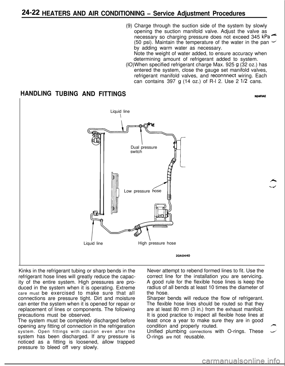
TUBINGANDFITTINGSLiquid line
\
IDual pressure
switch
Low pressure
Liquid lineHigh pressure hose
20A0440Kinks in the refrigerant tubing or sharp bends in the
refrigerant hose lines will greatly reduce the capac-
ity of the entire system. High pressures are pro-
duced in the system when it is operating. Extreme
care must be exercised to make sure that all
connections are pressure tight. Dirt and moisture
can enter the system when it is opened for repair or
replacement of lines or components. The following
precautions must be observed.
The system must be completely discharged before
opening any fitting of connection in the refrigeration
system. Open fittings with caution even after the
system has been discharged. If any pressure is
noticed as a fitting is loosened, allow trapped
pressure to bleed off very slowly.Never attempt to rebend formed lines to fit. Use the
correct line for the installation you are servicing.
A good rule for the flexible hose lines is keep the
radius of all bends at least 10 times the diameter of
the hose.
Sharper bends will reduce the flow of refrigerant.
The flexible hose lines should be routed so that they
are at least 80 mm (3 in.) from the exhaust manifold.
It is good practice to inspect all flexible hose lines atleast once a year to make sure they are in good
condition and properly routed.
Unified plumbing connections with O-rings. These
O-rings are not reusable.
Page 1178 of 1216
24-34HEATERS AND AIR CONDITIONING - Evaporator
EVAPORATOR
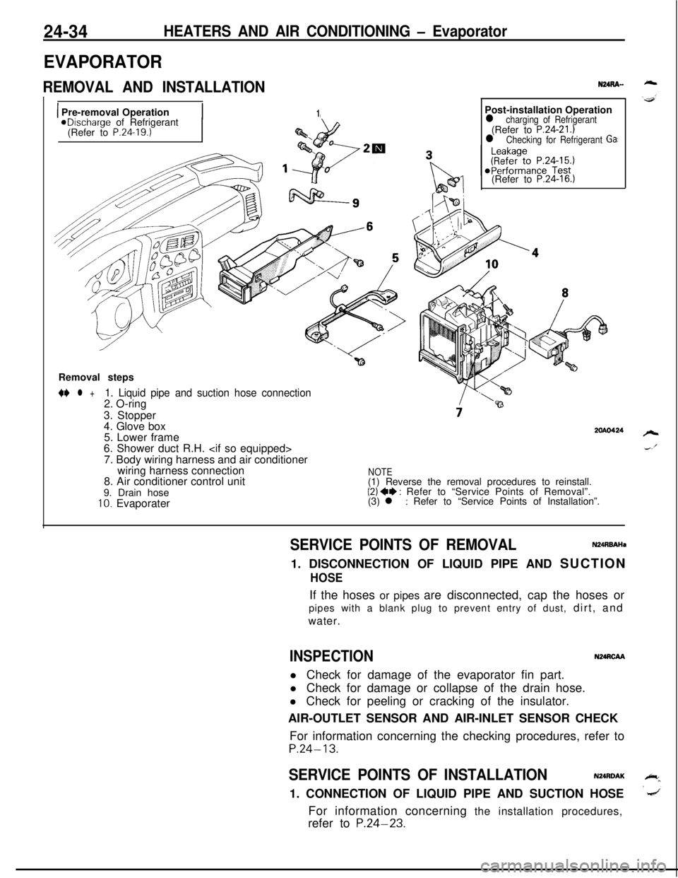
REMOVAL AND INSTALLATION
1 Pre-removal Operation1aDischarge of Refrigerant
(Refer to P.24.19.)Post-installation Operation
l charging of Refrigerant(Refer to P.24-21.)l Checking for Refrigerant Ga:(Refer to
P.24-16.)Removal steps
N l +1. Liquid pipe and suction hose connection2. O-ring
3. Stopper
4. Glove box
5. Lower frame
6. Shower duct R.H.
7. Body wiring harness and air conditioner
wiring harness connection
8. Air conditioner control unit
9. Drain hose
10. Evaporater
2OAO424
NOTE(1) Reverse the removal procedures to reinstall.
(2) ++ : Refer to “Service Points of Removal”.
(3) l : Refer to “Service Points of Installation”.
SERVICE POINTS OF REMOVALN24RBAHa1. DISCONNECTION OF LIQUID PIPE AND SUCTION
HOSEIf the hoses or pipes are disconnected, cap the hoses or
pipes with a blank plug to prevent entry of dust, dirt, and
water.
INSPECTIONN24RCAAl Check for damage of the evaporator fin part.
l Check for damage or collapse of the drain hose.
l Check for peeling or cracking of the insulator.
AIR-OUTLET SENSOR AND AIR-INLET SENSOR CHECK
For information concerning the checking procedures, refer to
P.24-13.
SERVICE POINTS OF INSTALLATIONN24RDAK1. CONNECTION OF LIQUID PIPE AND SUCTION HOSE
For information concerning the installation procedures,
refer to
P.24-23.
Page 1179 of 1216
HEATERS AND AIR CONDITIONING - Evaporator
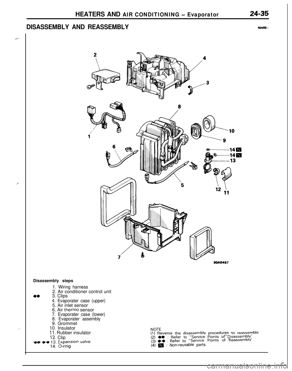
DISASSEMBLY AND REASSEMBLY
24-35
NURE--
3ZOAO457Disassembly steps
1. Wiring harness2. Air conditioner control unit
4*3. Clips4. Evaporater case (upper)5. Air inlet sensor
6. Air therm0 sensor
7. Evaporater case (lower)
8. Evaporater assembly9. Grommet
IO. Insulator11. Rubber insulator
12. Clip+) ++ 13. Expansion valve14. O-ringNOTE
(1) Reverse the disassembly procedures to reassyyble(2) ~~ : Refer to “Service Points of Disassembly,(3) +4 : Refer to“Service Points of Reassembly
(4) m : Non-reusable parts.
.