1991 MITSUBISHI ECLIPSE wiring
[x] Cancel search: wiringPage 226 of 1216

BRAKES - G-sensor
G-SENSOR
REMOVAL AND INSTALLATION
14AO595
NOTEReverse the removal procedures to reinstall.
G-sensor removal steps
1. Wiring harness connector
2. G-sensor3. G-sensor bracket
14AO194
14A0195
INSPECTION
(1)Place the sensor on a level surface, then check that there isconductance between the terminals.
(2) Slowly inclining the G-sensor in the direction of forward
vehicle travel, check that there is no conductance above a
sensor angle of 30 degrees.
Page 302 of 1216

9-18ENGINE - Specifications
TORQUE SPECIFICATIONS
NO9CG-Items
Engine mount insulator nut (large)
(small)
Engine mount bracket nut or bolt
Transaxle mount insulator nut
Transaxle mount to body
Front roll stopper insulator nut
Front roll stopper bracket to centermember
Rear roll stopper insulator nut
Rear roll stopper bracket to centermember
Accelerator cable adjusting bolts
Fuel high pressure hose to delivery pipe
Ground cable to air intake manifold
Control wiring harness to air intake plenum
Power steering oil pump to bracket
Air conditioner to bracketcompressor
Exhaust pipe clamp bolt
Exhaust pipe to rubber hanger
Oil drain plug
panOil (bolts)
pan(nuts)VVater pulley
pump
Tensioner pulley bracket (air conditioner compressor)
Timing belt front coverCrankshaft sprocket
Camshaft sprocket
Timing belt “B” tensioner bolt
-eft engine support bracket3il switch
pressure3il unit
pressure gauge
Iii filter bracket
Iii cover
pumpqelief plug
‘lywheel or drive plate
ixhaust pipe bracket
support
‘rant roll stopper bracket
Iear roll stopper bracket‘rant engine bracket
support
:1.8L Engine>
Oil screen
Rocker cover
Camshaft bearing cap bolt (6 x 20)
(8 x 65)
Exhaust pipe to exhaust manifold
Intake manifold bolt
stay
Cylinder head bolt
Crankshaft pulley
Crankshaft damper pulleyNm
ftlbs.
60-8043-58
30-4022-29
50-6536-47
60-8043-58
40-5029-36
50-6536-47
40-5029-36
40-5029-36
40-5029-36
4-63-4
4-6
3-4
4-6
3-4
4-6
3-4
35-45
25-33
23-27
17-20
30-4022-29
10-157-l 135-45
25-33
6-84-6
5-73.5-5
8-106-7
23-27
17-20
10-127-9
110-13080-94
80-10058-72
15-2211-16
30-4222-308-126-9
8-126-9
15-2211-16
15-1811-13
40-5029-36
130-14094-101
30-4222-3055-75
40-54
110-13080-94
50-7036-51
18-2513-18
5-74-5
20-2714-2019-21
14-15
30-4022-29
18-2513-18
70-7551-5415-1811-13
15-1811-13
Page 315 of 1216

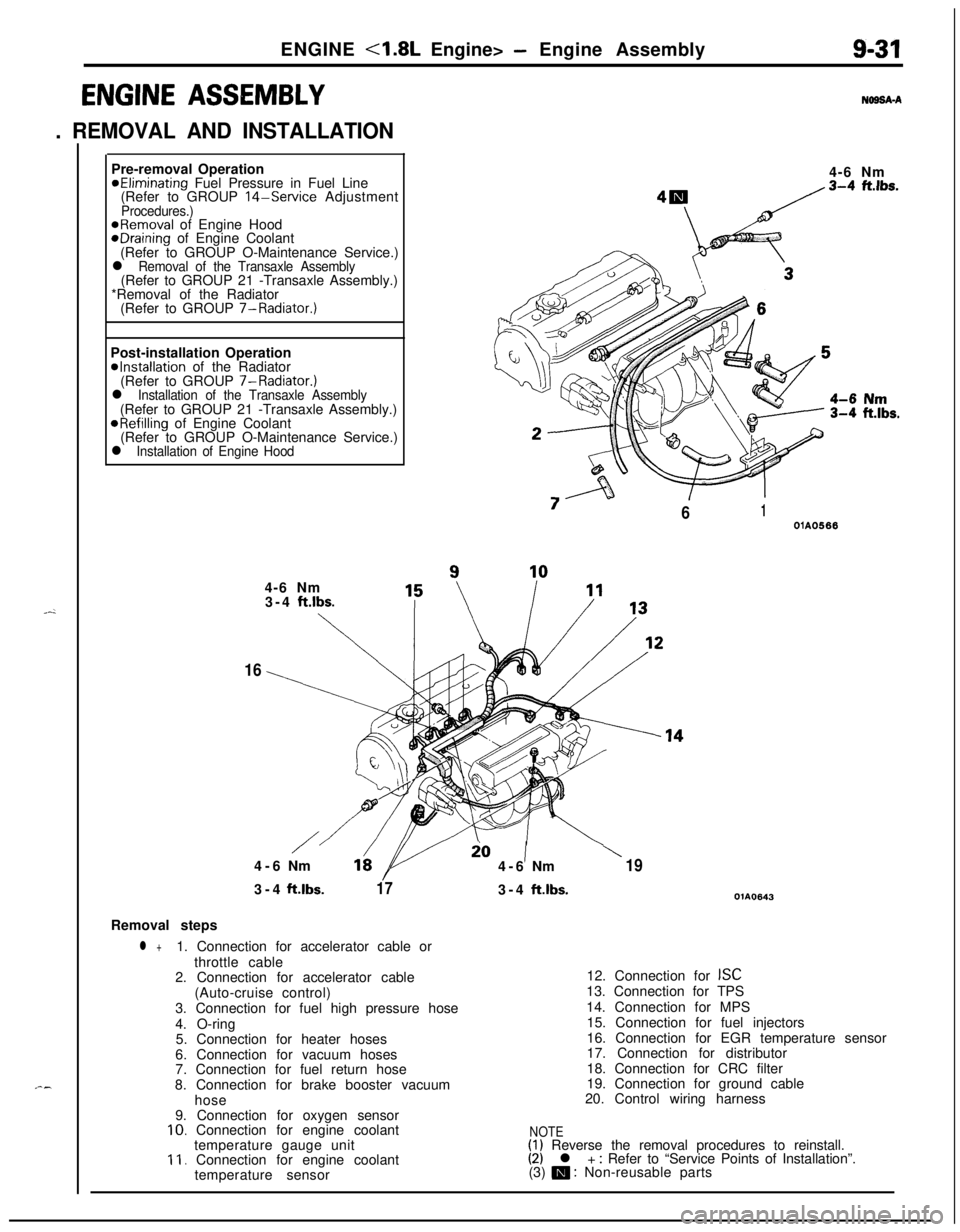
ENGINE <1.8L Engine> - Engine Assembly9-31
ENGINE ASSEMBLY
. REMOVAL AND INSTALLATION
N69SA-APre-removal Operation
@Eliminating Fuel Pressure in Fuel Line
(Refer to GROUP 14-Service AdjustmentProcedures.)@Removal of Engine HoodeDraining of Engine Coolant
(Refer to GROUP O-Maintenance Service.)
l Removal of the Transaxle Assembly(Refer to GROUP 21 -Transaxle Assembly.)
*Removal of the Radiator
(Refer to GROUP 7-Radiator.)
Post-installation Operation
@Installation of the Radiator
(Refer to GROUP 7-Radiator.)
l Installation of the Transaxle Assembly(Refer to GROUP 21 -Transaxle Assembly.)
@Refilling of Engine Coolant
(Refer to GROUP O-Maintenance Service.)
l Installation of Engine Hood4-6 Nm
“7
/61OlA05664-6 Nm
3-4
ft.lbs.
\
16
/io1\4-6Nm164-6Nm193-4ft.lbs.
173-4ft.lbs.OlA0643Removal steps
l +1. Connection for accelerator cable or
throttle cable
2. Connection for accelerator cable
(Auto-cruise control)
3. Connection for fuel high pressure hose
4. O-ring
5. Connection for heater hoses
6. Connection for vacuum hoses
7. Connection for fuel return hose
8. Connection for brake booster vacuum
hose
9. Connection for oxygen sensor
10. Connection for engine coolant
temperature gauge unit
11. Connection for engine coolant
temperature sensor12. Connection for
ISC13. Connection for TPS
14. Connection for MPS
15. Connection for fuel injectors
16. Connection for EGR temperature sensor
17. Connection for distributor
18. Connection for CRC filter
19. Connection for ground cable
20. Control wiring harness
NOTE(1) Reverse the removal procedures to reinstall.(2) l + : Refer to “Service Points of Installation”.
(3) m : Non-reusable parts
Page 320 of 1216

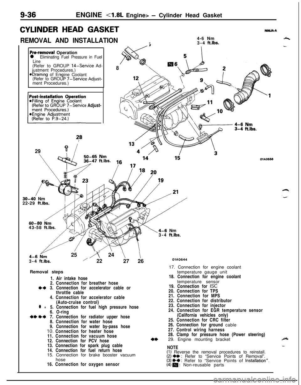
9-36ENGINE
CYLINDER HEAD GASKET
REMOVAL AND INSTALLATION4-6 Nm
73-4 ft.lbs.
NWJA-A
Pre-removal Operationl Eliminating Fuel Pressure in Fuel
Line(Refer to GROUP
14-Service Ad-
justment Procedures.)*Draining of En
ine Coolant
(Refer to GRO9P -/-Service Adjust-ment Procedures.)
(Refer to GROUP
7-Service Adjust-~~~~~~~n
?*
29?i
8
30-46 Nm
22-29 ft.lbs.
60-80 ium43-58 ftlbs.25
iy 24 \\3-4
ftlbs./2227 26
Removal steps
1. Air intake hose
2. Connection for breather hose
I)43. Connection for accelerator cable or
throttle cable
4. Connection for accelerator cable
(Auto-cruise control)
l +5. Connection for fuel high pressure hose
6. O-ring
+e W7. Connection for radiator upper hose
8. Connection for water hose
9. Connection for water by-pass hose
10. Connection for heater hose
11. Connection for vacuum hose
12. Connection for PCV hose
13. Connection for spark plug cable
14. Connection for fuel return hose
15. Connection for brake booster vacuum
hose
16. Connection for oxygen sensor
1\4-6 Nm
3-4 ftlbs.
OlAO556
QlAO64417. Connection for engine coolant
temperature gauge unit
18. Connection for engine coolant
temperature sensor
19. Connection for
ISC20. Connection for TPS
21. Connection for MPS
22. Connection for distributor
23. Connection for injector
24. Connection for EGR temperature sensor
(California vehicles only)
25. Connection for CRC filter
26. Connection for ground cable
27. Control wiring harness
28. Clamp for pressure hose (Power steering)
29. Engine mounting bracket
NOTE
(I) Reverse the removal procedures to reinstall.(2) Ce : Refer to “Service Points of Removal”.(3) ++ : Refer to “Service Points of Installation”.(4) m : Non-reusable parts
Page 365 of 1216

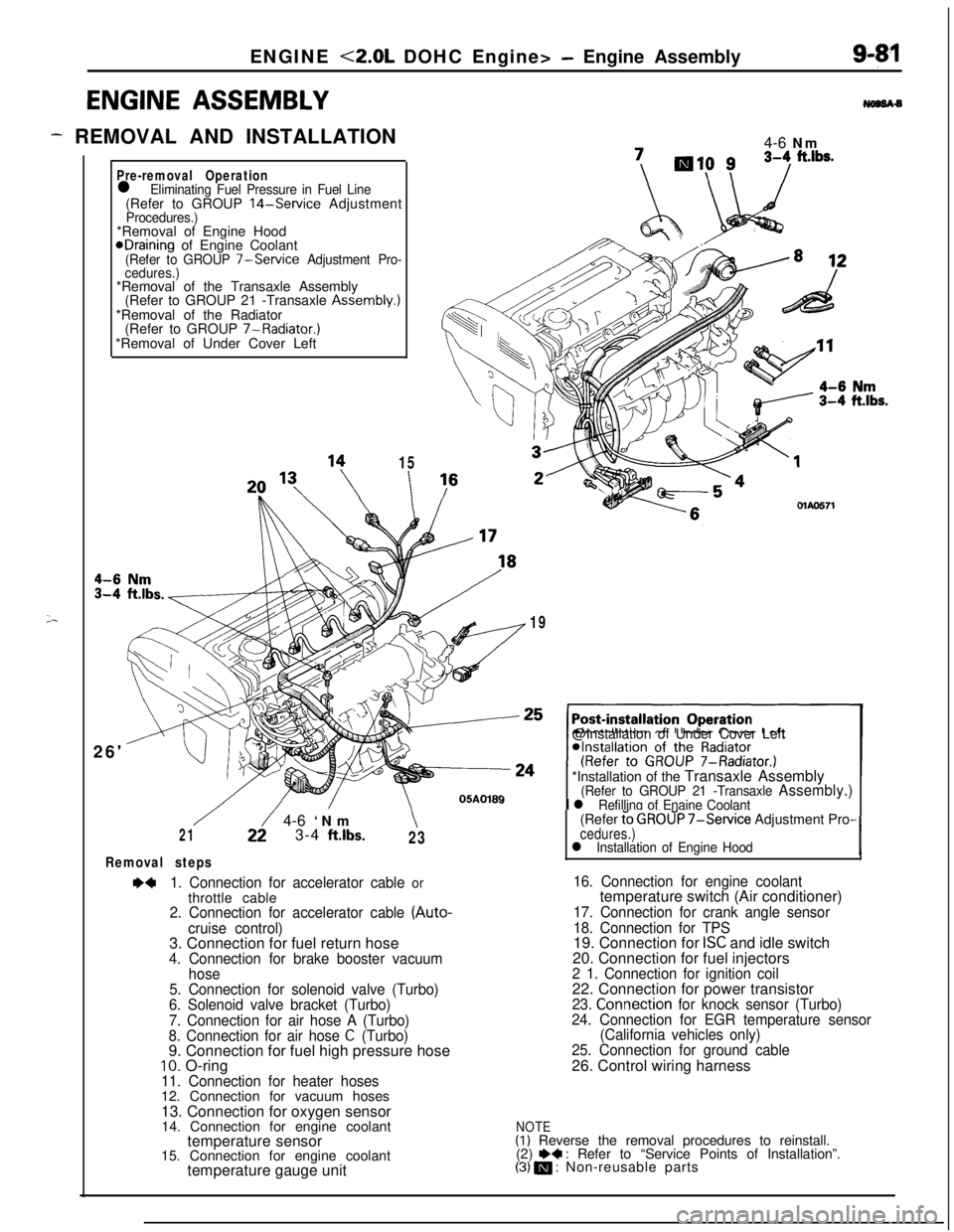
ENGINE <2.0L DOHC Engine> - Engine Assembly
ENGINE ASSEMBLY
- REMOVAL AND INSTALLATION
;-
Pre-removal Operationl Eliminating Fuel Pressure in Fuel Line(Refer to GROUP 14-Service AdjustmentProcedures.)*Removal of Engine Hood
@Draining of Engine Coolant(Refer to GROUP 7-Service Adjustment Pro-
cedures.)*Removal of the Transaxle Assembly
(Refer to GROUP 21 -Transaxle Assembly.)
*Removal of the Radiator
(Refer to GROUP 7-Radiator.)
*Removal of Under Cover Left
26'
15
I4-6 Nm\I /MAO571
19@Installation of Under Cover Left
*Installation of the Transaxle Assembly
(Refer to GROUP 21 -Transaxle Assembly.)
I l Refilling of Enaine Coolant
/22/ 4-6 ‘Nm\213-4 ftlbs.23
Removal steps
~~1. Connection for accelerator cable orthrottle cable
2. Connection for accelerator cable (Auto-
cruise control)3. Connection for fuel return hose
4. Connection for brake booster vacuum
hose
5. Connection for solenoid valve (Turbo)
6. Solenoid valve bracket (Turbo)
7. Connection for air hose A (Turbo)
8. Connection for air hose
C (Turbo)9. Connection for fuel high pressure hose
10. O-ring11. Connection for heater hoses12. Connection for vacuum hoses
13. Connection for oxygen sensor
14. Connection for engine coolant
temperature sensor
15. Connection for engine coolant
temperature gauge unit(Refer
t’o GROUP 7-Service Adjustment Pro-cedures.)l Installation of Engine Hood‘I
16. Connection for engine coolanttemperature switch (Air conditioner)
17. Connection for crank angle sensor
18. Connection for TPS19. Connection for
ISC and idle switch
20. Connection for fuel injectors
2 1. Connection for ignition coil22. Connection for power transistor
23. Connection for knock sensor (Turbo)
24. Connection for EGR temperature sensor
(California vehicles only)
25. Connection for ground cable26. Control wiring harness
NOTE(I) Reverse the removal procedures to reinstall.
(2) e+ : Refer to “Service Points of Installation”.(3) m : Non-reusable parts
Page 366 of 1216

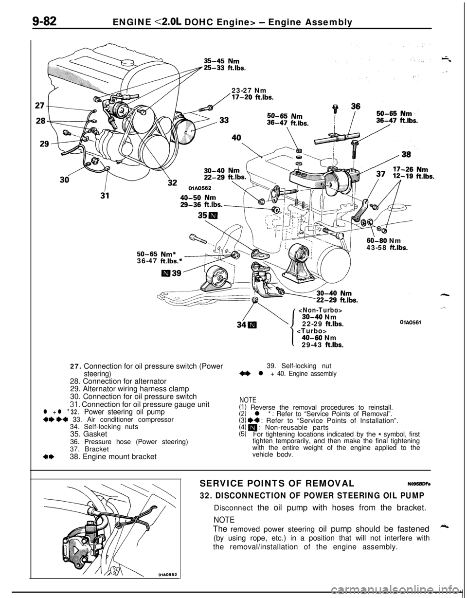
9-82ENGINE <2.0L DOHC Engine> - Engine Assembly
23-27 Nm
/17-20 ftlbs.
60-60 Nm
43-58 ft.lbs.50-65 Nm*36-47 ft.lbs.*27. Connection for oil pressure switch (Power
steering)28. Connection for alternator
29. Alternator wiring harness clamp
30. Connection for oil pressure switch
31, Connection for oil pressure gauge unitl + l * 32.Power steering oil pump+9 ~~ 33. Air conditioner compressor
34. Self-locking nuts
35. Gasket
36. Pressure hose (Power steering)
37. Bracket
4*38. Engine mount bracket
22-29 ftlbs.
.--
OlAO561
1
I40-60 Nm
29-43 ft.lbs.39. Self-locking nut
+e l + 40. Engine assembly
NOTE(I) Reverse the removal procedures to reinstall.(2) l * : Refer to “Service Points of Removal”.(3) I)+ : Refer to “Service Points of Installation”.(4) m : Non-reusable parts(5)For tightening locations indicated by the * symbol, first
tighten temporarily, and then make the final tightening
with the entire weight of the engine applied to the
vehicle bodv.
SERVICE POINTS OF REMOVALNOSSBDFa
32. DISCONNECTION OF POWER STEERING OIL PUMPDisconnect the oil pump with hoses from the bracket.
NOTEThe removed power steering oil pump should be fastened
A(by using rope, etc.) in a position that will not interfere with
the removal/installation of the engine assembly.
Page 565 of 1216

AUTO-CRUISE CONTROL SYSTEM - Troubleshooting144w
Auto-cruise control system cannot be set.
NOTEThis chart is to be used, then, for troubleshooting if it is not
possible to use the self-diagnosis for checking.
Prepare to conduct input check.
)( (Refer to P.14lrWhere codes
No.21, 22, 23, 25 and 26disolaved when, with the vehicle stationary,the’ input check codes were recalled?
‘#
No-8
cArc-3 ttie results of all inout checks normals?
L--y--
I
Check resultsProbable causeRemedy
ii”,:” chart
Code 21 remains even though SETSET switch ON mal-Replace the controlNo.2switch
is set to OFF.functionswitch
SET switch input lineRepair the harnessshort-circuit
:-Code 22 remains even though RE-SUME switch is set to OFF.RESUME switch ONmalfunction
RESUME switch input
line short-circuit
Replace the controlswitch
Repair the harnessNo.3
Code 23 is not canceled even if theMalfunction of stopReplace stop lightNo.6stop light switch
is turned OFF bylight switch circuit.switch or repair har-
releasing the brake pedal.ness.
Code 25 does not disappear, andMalfunction of theCheck or repair theNo.4
code 24 does not appear, evenvehicle-speed sensorvehicle speed sensor
though vehicle speed reaches appro-circuit (damaged or dis-circuit.ximately
40 km/h (25 mph) or higher.connected wiring, orshort-circuit)
Code 26 is not canceled even if theclutch switch is turned OFF by re-leasing the clutch pedal.Malfunction of clutch
switch circuit.
Replace clutch switchNo.8or repair harness.
Code 26 is not canceled even if theMalfunction of inhibitorReplace inhibitor switchNo. 7select lever is moved to anything butswitch circuit.or repair harness.
N, P
the auto-cruise vacuum pump circuit.NOTE_. . . e_,1 (Go to check chart No.5.)IIf the results of the check oT tne auro-crutse vacuum pump
circuit (check chart No. 5) and of the auto-cruise vacuum pump
and actuator itself (P.14-138.) reveal no abnormal
condition,replace
the electronic control unit (ECU).
-.
Page 566 of 1216

14-112AUTO-CRUISE CONTROL SYSTEM - Troubleshootina
Trouble symptomProbable causeCheck chart No.Remedy
l The set vehicle speed variesMalfunction of the vehi-No.4Repair the vehicle speec
greatly upward or downward.cle speed sensor circuitsensor system, or re-l “Hunching”
(repeated alternatingplace the part.
acceleration and deceleration)Malfunction of the
occurs after setting is made.speedometer cable orspeedometer drive gearAuto-cruise
vacuumNo.5Repair the auto-cruise
pump circuit poor con-vacuum pump, ortactreplace the part.Malfunction of the
auto-
cruise vacuum pumpMalfunction of the
ECU-Replace the ECU.
The auto-cruise control system is notDamaged or discon-If the input check codeRepair the harness or
canceled when the brake pedal isnetted wiring of theNo. 23 indicates a mal-replace the stop light
depressed.stop light switch inputfunction. No. 6switch.circuit; brake switch (forauto-cruise control) mal-function (short-circuit)Auto-cruise
vacuumNo. 5Repair the harness or
pump drive circuit short-replace the auto-cruisecircuitvacuum pump.Malfunction of the
ECU-Replace the ECU.
The auto-cruise control system is notDamaged or discon-If the input check codeRepair the harness, or
canceled when the clutch pedal isnetted wiring of clutchNo. 26 indicates a mal-repair or replace the
depressed. (vehicles with a manualswitch input circuitfunction. No. 8clutch switch.
transaxle)(It is canceled, however, when theClutch switch improper
brake pedal is depressed.)installation (won’tswitch ON)Malfunction of the
ECU-Replace the ECU.
The auto-cruise control system is notDamaged or discon-If the input check codeRepair the harness, orcanceled when the shift lever isnetted wiring of inhibi-No. 26 indicates a mal-repair or replace the in-
moved to the “N” position. (vehiclestor switch input circuitfunction. No.7hibitor switch.llvith an automatic transaxle)
[It is canceled, however, when theImproper adjustment of
Drake pedal is depressed.)inhibitor switchMalfunction of the
ECU-Replace the ECU.
Cannot decelerate by using the SETTemporary damaged orNo. 2Repair the harness orswitchdisconnected wiring ofreplace the SET switch.SET switch input circuitAuto-cruise
vacuumNo.5Repair the harness orpump circuit poor con-replace the auto-cruisetactvacuum pump andactuator.Malfunction of the auto-cruise vacuum pump
and actuator (includingclogging of negativepressure passage)Malfunction of the
ECU-Replace the ECU.