Page 1087 of 1216
BODY - Rear Bumper23-43
REAR BUMPER
- REMOVAL AND INSTALLATION
< Normal type >
N23ZAAV
0 Removal of Rear End Trim(Refer to P.23-85.)
JI0 lnstallatron of Rear End Tnm
18A0452
Rear bumper assembly removal steps1. Splash shield mounting clip
2. Rear panel garnish3. Rear combination light
4. Connection for license plate light wiring
harness and body wiring harness
5. Rear bumper assembly
8. Fascia plate upper
9. Rear bumper reinforcement assembly
10. Fascia plate lower
11. Rear bumper fascia
Rear bumper fascia removal steps1. Splash shield mounting clip
2. Rear panel garnish3. Rear combination light
6. License plate light harness connector
7. Back-up light harness connector
8. Fascia plate upper
10. Fascia plate lower11. Rear bumper fascia
NOTEReverse the removal procedures to reinstall.
Page 1088 of 1216
< Large type >
]0 lnstallatron of Rear End Tnm
23-44BODY - Rear Bumper
18AO722
Rear bumper assembly removal steps1. Splash shield mounting clip
2. Rear panel garnish3. Rear combination light
4. Connection for license plate light wiring
harness and body wiring harness
5. Rear bumper assembly8. Fascia plate upper
9. Rear bumper reinforcement assembly
10. Fascia plate lower11. Rear bumper fascia
Rear bumper fascia removal steps1. Splash shield mounting clip
2. Rear panel garnish3. Rear combination light
6. License plate light harness connector
7. Back-up light harness connector
8. Fascia plate upper
10. Fascia plate lower
11. Rear bumper fascia
NOTEReverse the removal procedures to reinstall.
Page 1089 of 1216
BODY - Rear Bummer23-45
DISASSEMBLY AND REASSEMBLY<
Normal type >
Disassembly steps1. License plate light
2. Back-up light
3. Rear side marker light
4. License plate light wiring harness
5. Bumper absorber
6. Rear bumper reinforcement
7. License plate bracket
8. Rear bumper fasciaNOTE
(1) Reverse the disassembly procedures to reassemble.(2) +* : Refer to “Service Points of Disassembly”.
SERVICE POINTS OF DISASSEMBLY5. REMOVAL OF BUMPER ABSORBER
Caution1. Do not attempt to repair a bumper absorber that has
been compressed in an accident; replace it with a new
one.2. Before discarding the bumper absorber, drill a 3 mm
(. 13 in.) diameter hole to discharge the gas containedin the unit.
3.
If the bumper absorber is to be discarded, do not burn
it.
Page 1090 of 1216
23-46BODY - Rear Bumper
< Large type >
517-26 Nm
18A0721
Disassembly steps1 License plate light
2. Back-up light
3. Rear side marker light
4. License plate light wiring harness
4*5. Bumper absorber6. Rear bumper reinforcement
7. License plate bracket
8. Rear bumper fascia
SERVICE POINTS OF DISASSEMBLY5. REMOVAL OF BUMPER ABSORBER
Caution1. Do not attempt to repair a bumper absorber that has
been compressed in an accident; replace it with a new-one.
-F--2. Before discarding the bumper absorber, drill a 3 mm
-z
(. 13 in.1 diameter hole to discharge the gas containedin the unit.
3.
If the bumper absorber is to be discarded, do not burn
it.
Page 1107 of 1216
BODY - Door AssemblvDOOR ASSEMBLY
- REMOVAL AND INSTALLATION
N22MAW17-26
12-19
17-26
12-19
15A0511
Removal steps
1. Connection for door wiring harness
connector
*+ 2. Spring pin
3. Door assembly
l 4. Upper hinge
.c 5. Lower hinge6. Striker7. Striker shim
8. Door switch cap
9. Door switch
l * 10. Door check strap
0 Removal of Cowl Side Trim(Refer to P.23-85.)
l Installation of Cowl Side Trim(Refer to P.23-85.)
0 Door Adjustment
NOTE(I) Reverse the removal procedures to reinstall.(2) I)+ : Refer to “Service Points of Instal$tion”.
Page 1127 of 1216
BODY - Instrument Panel23-83
191026024. Air duct
(A)25. Air duct
(B)26.Distribution duct
27.Side defroster hoses
28. Defroster nozzle assembly
29. Side defroster grilles
30. Side air outlet assembly
31. Bracket
32. Combination meter wiring harness
connector connections33. Instrument panel wiring harness
34. Instrument panel pad
35.Vin plate
36.Instrument
panel
NOTE(I) Reverse the disassembly procedures to reassemble(2) 4, : Refer to “Service Points of Disassembly”.
SERVICE POINTS OF DISASSEMBLY32. DISCONNECTION OF COMBINATION METER WIRING
HARNESS CONNECTORS
Insert a flat-tip I- 1 screwdriver and open the tab of the
connector, and then remove the harness connectors.
Page 1128 of 1216
Page 1138 of 1216

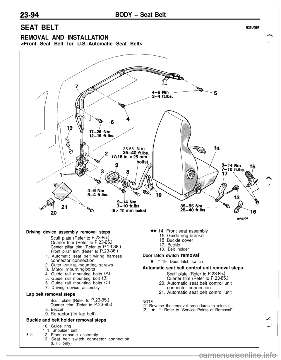
23-94BODY - Seat Belt
SEAT BELT
REMOVAL AND INSTALLATION
N23UQBF
/
//35-55 Nm
25-40 ft.lbs.U/16 in. x 25 mm
bolts) ,n(8 x 20 mm
bolts)
Driving device assembly removal steps
Scuff plate (Refer to P.23-85.1Quarter trim (Refer to P.23-85.)Center pillar trim (Refer to P.23-86.)
Front pillar trim (Refer to P.23-86.)
1. Automatic seat belt wiring harness
connector connection
2. Outer
casinq mounting screws
3. Motor mouriting bolts-4. Guide rail mounting bolts (A)5. Guide rail mounting bolt (B)6. Guide rail mounting bolts (Cl
7. Driving device assembly
Lap belt removal steps
Scuff plate (Refer to P.23-85.)
Quarter trim (Refer to P.23-85
8. Bezzel
9. Retractor (for lap belt)
Buckle and belt holder removal steps
10. Guide ring
l *1 1. Shoulder belt
12. Floor console assembly
13. Seat belt switch connector connection
(L.H. only)
25-4.0 ft.lbs.
w 14. Front seat assembly
15. Guide ring bracket
16. Buckle cover
17. Buckle18. Belt holder
Door latch switch removall * 19. Door latch switch
Automatic seat belt control unit removal steps
Scuff plate (Refer to P.23-85.)Quarter trim (Refer to P.23-85.)20. Automatic seat belt control unit
connector connection
21. Automatic seat belt control unit
NOTE(1) Reverse the removal procedures to reinstall.(2) l * : Refer to “Service Points of Removal”