Page 883 of 1216

AUTOMATIC TRANSAXLE - Troubleshooting21-189
_ 4, ppBgeneratorCheck the resistance betweenterminals 1 and 2 or 3 and 4.Short-circuit; or
dam-aged or disconnectedwiring
:
I
.
4
/
NormalI
1750338II\
Pulse generator terminals.(215-275 Q/2O”C (68°F)1
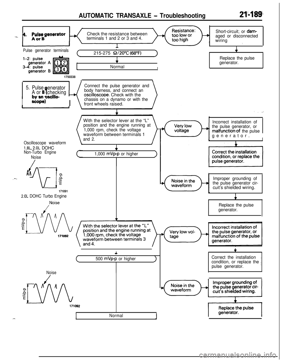
5. PulseeneratorConnect the pulse generator and
A or B?checkingwbody harness, and connect an
+ mm narillroscilloscooe. Check with the\
I
#, -mm v3nlwdP
scope)I \
chassis on a dynamo or with thefront wheels raised.
With the selector lever at the “L”
position and the engine running at
1,000 rpm, check the voltagewaveform between terminals 1
and 2.
Oscilloscope waveform
1,8L, 2.0L DOHCNon-Turbo Engine
Noise
/AA_--
iw
5E4
1,000 mVp-p or higher>
171091
2.0L DOHC Turbo Engine
,Noise
Replace the pulse
generator.
. . .,’
Incorrect installation of
the pulse generator, or
malfunction,of the pulsegenerator.
II
Improper grounding of
the pulse generator cir-cuit’s shielded wiring.
i
Replace the pulse
generator.+
(500 mVp-p or higherJ
Noise
Normal1
+,I
Correct the installation
condition, or replace the /pulse generator.
Page 884 of 1216
21490AUTOMATIC TRANSAXLE - Troubleshooting6.
Pressure-Check the resistance between
terminal 1 of the solenoid valve
connector and the transaxle case.Short-circuit, or’@, ,,n-
1:aged or disconnectedwiring1
Solenoid valve
connector terminalsConnect
12V between the trans-
axle case and terminal 2;
switch ON and OFF and check for
operation noise.” ,“,
Foreign material caught
between the valve andguide1 .
1:
PCSV
2: DCCSV
3: SCSV-A4:
scsv-B
7. Shift-control
solenoid valve
(SCSV) A or Bt
Check the resistance between
terminal 3 or 4 of the solenoid
valve connector and the transaxle
case.t
4
c-22.3 f l.5Q/20°C (68°F)J
I
Replace the PCSV.
I
Short-circuit, or dam-+
aged or disconnectedwiring4
Replace the SCSV..Connect
12V between the trans-axle case and terminal 3 or 4;
switch ON and OFF and check for
operation noise of the solenoid
valve, and check the valve stroke.
~~~~~
4Noise exists.
I
NormalIa
/
Page 886 of 1216
21-192AUTOMATIC TRANSAXLE - Troubleshooting
9. Damper clutchcontrol solenoid
valve (DCCSV)
1,8L, 2.0L DOHC
Non-Turbo
Engine
Solenoid valve
connector terminals1:
PCSV2: DCCSV
3: SCSV-A4:
SCSV-B
1750338Check the resistance between
terminal 2 of the solenoid valve
connector and the transmission
case.too low or too
G’Short-circuit
0,s” dam-
aged or d&connectedwiring
.: ’
I
(Standard value: 3 Q/20%)I
INormalI*Sticking *Sticking
is isusually at the usually at the
release side. release side.
1 Replace the DCCSV. 1
171096
b adjust if necessary.
Replace the acceleratorswitch.
(No continuity (resistance: Q)))4
Normal
Page 898 of 1216
21-204AUTOMATIC TRANSAXLE - Troubleshooting
c;_----__---___-.
IGNITIONSWITCH(IG2)0
?
3E-7r
0
1UA
\IEjC-53mJ
ca (LB)
POWER/
ECONOMY
;$;;E OVER "r-
D-19A, .
12l!i3Fl3453$
,F
IGHT
3 19 ~lo~ll~l2~la~lq1qls
E
A/T SELECTOR
LEVER POSITION
ILLUMINATIONLIGHT
WITHOUTAU;iUi~;UISE
hf---
II
sP5 11
LIEI
AUTO-
CRUISE
CONTROL
UNIT
Y
-t
______--___---__--------
4
gF
C-61 57_______-__-----_---_-----
J/B
Remark**Mark indicates the oPtional wiringFEI~~I;S for auto-cruise control
Page 911 of 1216
AUTOMATIC TRANSAXLE - Transaxle Control21-217
TRANSAXLE CONTROL
dl_i REMOVAL AND INSTALLATIONNZlub-
-.
lo-14 Nm7-10 ft.lbs.
i284-6
Nm
y-14 Nm7-10 ft.lbs.
Transaxle control cable and selector lever
assembly removal steps
1. Plug2. Side cover (B)3. Power (PWR)/Economy (ECO) switch
4. Side cover(B)
5. Cover(B)
6. Cup holder7. Carpet
8.
EZrreTstion of floor console wiring
9. Guide ring
IO. Shoulder belt 11. Floor console
17. Snap pin18. Key interlock cable (selector lever
assembly side)
23.
S$i; lock cable (selector lever assembly
26. Snap pin27. Clip
28. Adjusting nut
l 4 29. Clip++ 30. Transaxle control cable31. Selector lever assembly
zykeverse the removal procedures to reinstall.(2) l + : Refer to “Service Points of Installation”
Page 912 of 1216

2l-218AUTOMATIC TRANSAXLE - Transaxle Control
724
169-14
Nm7-10 ftlbs.7
\\4-6 Nm3-4 ft.lbs.3-4
ft.lbs.
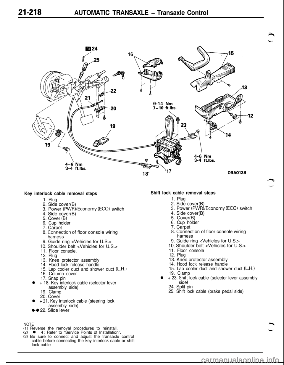
Key interlock cable removal steps
1. Plug2. Side cover(B)
3. Power
(PWR)/Economy (ECO) switch
4. Side cover(B)
5. Cover
(B)6. Cup holder7. Carpet
8.
;ir;eystion of floor console wiring
9. Guide ring
10. Shoulder belt 11. Floor console.
12. Plug
13. Knee protector assembly
14. Hood lock release handle
15. Lap cooler duct and shower duct
(L.H.)16. Column cover
17. Snap pin
l + 18. Key interlock cable (selector lever
assembly side)
19. Clamp20. Cover
l + 21, Key interlock cable (steering lock
assembly side)
e+ 22. Slide lever
NOTE(I) Reverse the removal procedures to reinstall.(2) l 4 : Refer to “Service Points of Installation”.(3) Be sure to connect and adjust the transaxle control
cable before connecting the key interlock cable or shift
lock cable18'
‘1709A0138
Shift lock cable removal steps
1. Plug2. Side cover(B)
3. Power
(PWR)/Economv (EC01 switch
4. Side cover(B)
’5. Cover(B)
6. Cup holder7. Carpet
8. Connection of floor console wiring
harness9. Guide ring
10. Shoulder belt
11. Floor console
12. Plug13. Knee protector assembly
14. Hood lock release handle
15. Lap cooler duct and shower duct (L.H.)19. Clamp
l + 23. :izs lock cable (selector lever assembly24. Split pin
25. Shift lock cable (brake pedal side)
Page 1022 of 1216
21-328AUTOMATIC TRANSAXLE - Valve Bodv
XSV-ASkV-Brj,,SV (FJA22)TFAM80(3) After securing the lower valve body by
the installationbolt, remove the special tool.
Sk
5./4./3./2. INSTALLATION OF SOLENOID VALVE ASSEM-
BLYInstall each solenoid valve in the position shown in the
figure.
Solenoid valveWiring colorI
Shift control solenoid valve “A”
Shift control solenoid valve “B”
Damper clutch control solenoid valve
Yellow
Red
Pressure control solenoid valveBlue
Page 1080 of 1216

23-36BODY - Liftgate
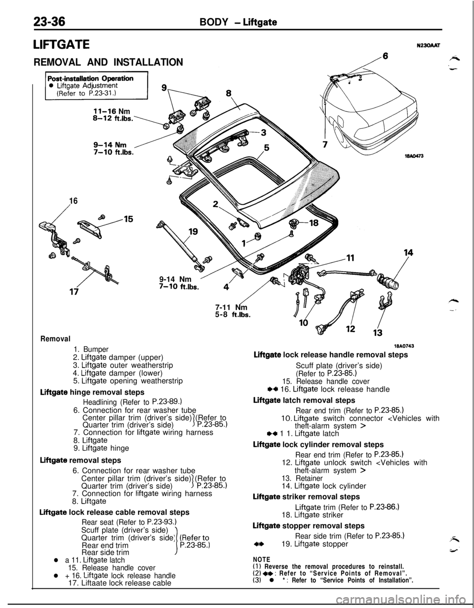
LIFTGATEN230AAT
REMOVAL AND INSTALLATION/
11-16 Nm
16
/9-14 Nm
’7-10 ft.lbs.
“‘/- -$j7-11 Nm
5-8
ft.lbs.
Removal
1. Bumper2.
Liftgate damper (upper)
3.
Liftgate outer weatherstrip
4.
Liftgate damper (lower)
5. Liftgate opening weatherstrip
Liftgate hinge removal steps
Headlining (Refer to P.23-89.16. Connection for rear washer tube
Center pillar trim (driver’s side) (Refer to
Quarter trim (driver’s side)
3P.23-85.)7. Connection for
liftgate wiring harness
8.
Liftgate9. Liftgate hinge
Liftgate removal steps
6. Connection for rear washer tube
Center pillar trim (driver’s side) (Refer to
Quarter trim (driver’s side)
1P.23-85.)7. Connection for
liftgate wiring harness
8.
Liftgate
Liftgate lock release cable removal steps
Rear seat (Refer to P.23-93.)Scuff plate (driver’s side)
Quarter trim (driver’s side) (Referto
Rear end trim
1P.23-85.)Rear side trim
l a 11. Liftgate latch
15. Release handle cover
l + 16. Liftgate lock release handle17. Liftaate lock release cable
WA0743
Liftgate lock release handle removal steps
Scuff plate (driver’s side)
(Refer to P.23-85.)15. Release handle cover
w 16. Liftgate lock release handle
Liftgate latch removal steps
Rear end trim (Refer to P.23-85.)10. Liftgate switch connector ,4 1 1. Liftgate latch
Liftgate lock cylinder removal steps
Rear end trim (Refer to P.23-85.112. Liftgate unlock switch
theft-alarm system >
13. Retainer14. Liftgate lock cylinder
Liftgate striker removal stepsLiftgate
trim (Refer to P.23-86.)18. Liftgate striker
Liftgate stopper removal steps
Rear side trim (Refer to P.23-85.)
c*19. Liftgate stopper
NOTE
(1) Reverse the removal procedures to reinstall.(2) 4* : Refer to “Service Points of Removal”.(3) l * : Refer to “Service Points of Installation”.