Page 567 of 1216

.z
c-AUTO-CRUISE CONTROL SYSTEM
- Tr6ubleshootina
Trouble symptom
Cannot accelerate or resume speed
by using the RESUME switch.
Probable cause
Damaged or discon-netted wiring, or short-circuit, of
RESUMEswitch input circuit
Remedy .’ ’-c liiCheck chart No.,;+ >,, a”:; : :
9 . /~ A%No.3.Repair theharness‘&
replace the RESUMEswitch.Auto-cruise
vacuumNo. 5Repair the harness orpump circuit poor con-replace the auto-cruisetact
vacuum,pump andactuator.Malfunction of the auto-cruise vacuum pumpand actuator (includingair leak from negativepressure passage)Malfunction of the
ECU.-Replace the ECU.
Auto-cruise control system can beMalfunction of theNo.4Repair the vehicle-set while
traveling at a vehicle speedvehicle-speed sensorspeed sensor system,
of less than 40 km/h (25 mph), orcircuitor replace the part.there
is no automatic cancellation atthat
speed.Malfunction of the‘I,speedometer cable orthe speedometer drive6 i
gear
The indicator light of combination
meter does not illuminate.
(But auto-cruise control system is
normal.)Malfunction
of control function by
ON/OFF switching of ELC 4 A/T
accelerator switch,Non-operation of damper clutch,
2nd gear hold, etc.)3verdrive
is not canceled during
‘ixed speed driving.
10 shift to overdrive during manual
driving. Malfunction of the
ECU-Replace the ECU.
Damaged or discon--Repair the harness or
netted bulb of indicatorreplace the bulb.light
Harness damaged ordisconnected
‘._,.Malfunction of circuit
re-No. 9Repair the harness or
lated to acceleratorreplace the part.switch
OFF functionMalfunction of the
ECUMalfunction of circuit
re-No. 10Repair the harness or
lated to overdrive can-replace the part.
cellation, or malfunction
of ECU
Page 579 of 1216
Page 709 of 1216
MANUAL TRANSAXLE - Transaxle Control2M5
TRANSAXLE CONTROL
-^ REMOVAL AND INSTALLATION
Removal steps1. Plug
2. Side cover (A)
3. Side cover(B)
4. Cover(B)
N21JA-A
919AO349
9-14 Nm .
+-
0
0OQA017412. Cotter pin
13. Retainer
14. Retainer
15. Cotter pin
9-14 Nm7- 10 ftlbs.5. Manual transaxle shift lever knob
6. Cup holder
7. Carpet
8. Connection for floor console wiring
I)4 16. Shift cable
I)+ 17. Select cable
18. Shift lever assembly
harness
9. Guide ring
10. Shoulder belt
11. Floor console
NOTE(1) Reverse the removal procedures to reinstall.(2) *a : Refer to “Service Points of Installation”.(3) m : Non-reusable parts
Page 716 of 1216

21-22MANUAL TRANSAXLE - Transaxle
1 Transaxleside1 Radiator lower hose
1 Transaxle side1 Radiator lower hosepart ofdrive shaft
I
-Transaxle
09LOO5819. REMOVAL OF TRANSAXLE ASSEMBLY
Caution
On the turbo vehicle, take care to prevent damaging
+Gthe lower hose of the radiator with the end of the
’transaxle housing.
As a protective countermeasure, wind tape around the
lower hose and the transaxle housing at the positions
shown in the figure.
Support the transaxle assembly by using a transaxle jack;
then, after moving the transaxle assembly to the right,
lower it.
NOTEWhen supporting the transaxle assembly by the transaxle
jack, take care to be sure that the jack’s force is applied to awide area, not to only a small localized area.
SERVICE POINTS OF INSTALLATION
NZlMDAP19. INSTALLATION OF TRANSAXLE ASSEMBLY
Caution
On the turbo vehicle, take care to prevent damaging
Athe lower hose of the radiator with the end of the
-transaxle housing.
As a protective countermeasure, wind tape around the
lower hose and the transaxle housing at the positions
shown in the figure.
15. INSTALLATION OF DRIVE SHAFT
(1) Provisionally install the drive shaft so that the inboard
joint part of the drive shaft is straight, and not bent
relative to the transaxle.
Caution
Care must be taken to ensure that the oil seal lip
part of the transaxle is not damaged by the serratedpart of the drive shaft.
(2) Align the serrations and securely insert the drive shaft
into the transaxle.
7. INSTALLATION OF STARTER
Tighten the starter installation bolts with the wiring harness
clip and the ground cable.
Page 874 of 1216

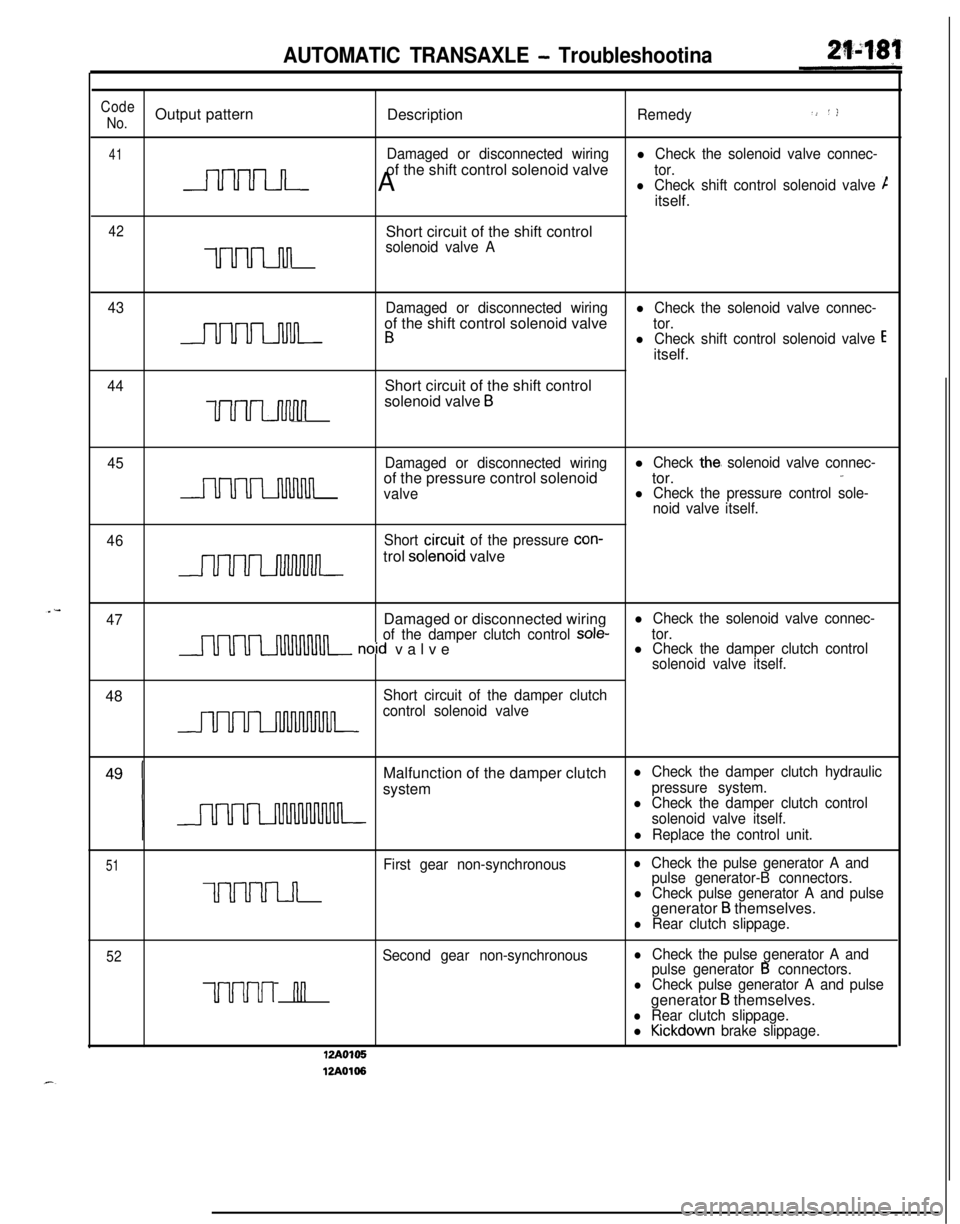
21480AUTOMATIC TRANSAXLE - Troubleshootina
FAULT CODE DESCRIPTION
Code
No.Output patternDescription
Remedy
11Abnormal increase of TPS outputl Check the throttle position sensor
nconnector.
l Check the throttle position sensoritself.
12l Adjust the throttle position sensor.
Abnormal decrease of TPS outputl Check the accelerator switch
(Code No. 24output
or not).Malfunction of the throttle-
position sensor or incorrect
adjustment
Damaged or disconnected wiringl Check the oil temperature sensorof low oil temperature sensor
connector.
l Check the oil temperature sensoritself.
16Short circuit of high oil tempera-ture sensor
Damaged or disconnected wiring
of high oil temperature sensor orshort-circuit of low oil tempera-
ture sensor
21
n
Damaged or disconnected wiringl Check the kickdown servo switchof the kickdown servo switch
connector.l Check the kickdown servo switch
itself.
22
nnShort circuit of the kickdown
ser-vo switch
23Damaged or disconnected wiringl Check the ignition pulse signal line.
of the ignition pulse pick-up cable24
Short circuit of the acceleratorswitch or improper adjustmentl Check the accelerator switch con-
nectar.l Check the accelerator switch itself.
l Adjust the accelerator switch.
31
u’u I n
Damaged or disconnected wiring
of the pulse generator AlCheck the pulse generator A and
pulse generator B themselves.l Check the vehicle speed reed
switch (for chattering).32
Damaged or disconnected wiring
uuLnJ-l-of the pulse generator B
12A0104
12A0107
Page 875 of 1216

AUTOMATIC TRANSAXLE - Troubleshootina
Code.> ‘)No.Output pattern
DescriptionRemedy
41Damaged or disconnected wiringl Check the solenoid valve connec-of the shift control solenoid valve
nnnn A
tor.lCheck shift control solenoid valve Citself.
42Short circuit of the shift control
uuu-mn
solenoid valve A
43Damaged or disconnected wiring
l Check the solenoid valve connec-of the shift control solenoid valve
- B
tor.l Check shift control solenoid valve Eitself.
44Short circuit of the shift control
uuvuwlnsolenoid valve B
45Damaged or disconnected wiringlCheck the, solenoid valve connec-,.
uuuumnof the pressure control solenoidtor.valvel Check the pressure control sole-
noid valve itself.
46
J-~-,,-=
Short circu.it of the pressure con-trol
solenoid valve
47Damaged or disconnected wiringl Check the solenoid valve connec-
of the damper clutch control
sole-nnnn~ noid valvetor.l Check the damper clutch control
solenoid valve itself.48
Short circuit of the damper clutchnnnncontrol solenoid valveMalfunction of the damper clutch
l Check the damper clutch hydraulicsystem
pressure system.l Check the damper clutch control
solenoid valve itself.
l Replace the control unit.
51First gear non-synchronouslCheck the pulse generator A and
UUUUI~
pulse generator-B connectors.l Check pulse generator A and pulsegenerator B themselves.l Rear clutch slippage.
52Second gear non-synchronouslCheck the pulse generator A and
pulse generator B connectors.
uuuul nnlCheck pulse generator A and pulsegenerator
B themselves.l Rear clutch slippage.l Kickdown brake slippage.
I-Y I”*
12Ao106
Page 876 of 1216

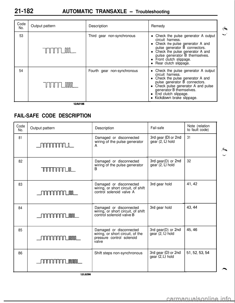
21-182AUTOMATIC TRANSAXLE - TroubleshootingDescription
Code
No.
53Output pattern
UUUULnnn-
Remedy
lCheck the pulse generator A output
circuit harness.
lCheck the pulse generator A and
pulse generator
B connectors.
lCheck the pulse generator A andpulse generator B themselves.
l Front clutch slippage.l Rear clutch slippage.
lCheck the pulse generator A output
circuit harness.
lCheck the pulse generator A and
pulse generator B connectors.
l Check pulse generator A and pulsegenerator
B themselves.
l End clutch slippage.
l Kickdown brake slippage. Third gear non-synchronous
54Fourth gear non-synchronous
uuuuLnMn-12A0106
FAIL-SAFE CODE DESCRIPTION
CodeNo.Output patternDescriptionFail-safeNote (relation
to fault code)
81Damaged or disconnectedwiring of the pulse generator
A3rd gear (D) or 2nd
gear (2, L) hold
31
3rd gear(D) or 2ndgear (2, L) hold
32Damaged or disconnectedwiring of the pulse generator
B
82
83
3rd gear hold41,42Damaged or disconnectedwiring, or short circuit, of shift
control solenoid valve A43,44
843rd gear hold
Damaged or disconnectedwiring, or short circuit, of shift
control solenoid valve
B
Damaged or disconnectedwiring, or short circuit, of the
pressure control solenoid
valve
45,463rd gear(D) or 2ndgear (2, L) hold85
86Shift steps non-synchronous3rd gear (D) or 2nd
gear (2, L) hold51,52,53,54
12LO296
Page 882 of 1216

21-188AUTOMATIC TRANSAXLE - Troubleshooting
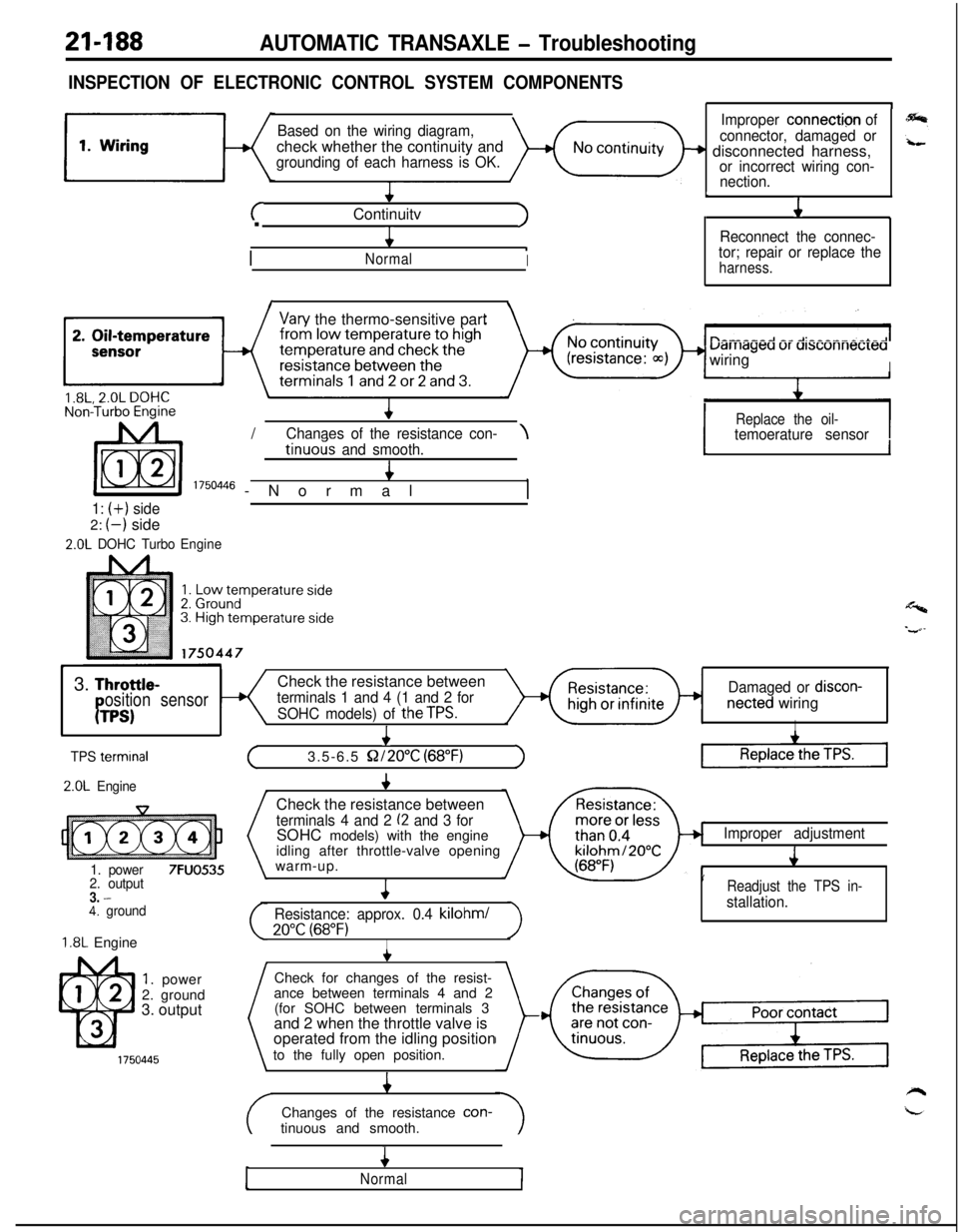
INSPECTION OF ELECTRONIC CONTROL SYSTEM COMPONENTS
Based on the wiring diagram,check whether the continuity and
grounding of each harness is OK.
+
cContinuitvJ.
4
/
.NormalI
1
Improper connection of
connector, damaged or
+ disconnected harness,or incorrect wiring con-
nection.
L
J1
Reconnect the connec-
tor; repair or replace the
harness.
I\
Vary the thermo-sensitive part
uarriageu ur ursconnecreawiring
I/
IReplace the oil-Chanaes of the resistance con-\temoerature sensortinuo& and smooth.4
I 1750446 -Normal,
1: (+) side2:
(-) side
2.0L DOHC TurboEngine
1I
Y3.
Throttle-Check the resistance betweenosition sensorterminals 1 and 4 (1 and 2 forDamaged or discon-
PTPS)SOHC models) of theTPS.netted wiringI
I
TPS termrnal
2.0L Engine
1. power
7FUO5352. output3. -4. ground
1.8L Engine
1. power
2. ground
3. output
+
(3.5-6.5 S2/2O”C (68°F)1Check the resistance between
terminals 4 and 2 (2 and 3 forSOHC models) with the engine
idling after throttle-valve opening
warm-up.
4
Resistance: approx. 0.4 kilohml
20°C (68°F)I
Improper adjustment
J
’Readjust the TPS in-
stallation.Check for changes of the resist-
ance between terminals 4 and 2
(for SOHC between terminals 3
and 2 when the throttle valve is
operated from the idling position
to the fully open position.
4Changes of the resistance con-
tinuous and smooth.
4
Normal