Page 406 of 1216
9-122ENGINE <2.0L DOHC Engine>- Front Case, Oil Pump and Silent ShaftMain gallery
Check valve6LUO14Left
rearbearing
6EN323
SERVICE POINTS OF REASSEMBLYNOSRHAG36. INSTALLATION OF OIL JET
;;;itWhen installing the oil jet, make sure that the nozzle is in
_correct direction, that is, toward the piston.
33. INSTALLATION OF LEFT SILENT SHAFT REAR BEAR-
ING
(1) Install the special (GUIDE PLATE) tool to the cylinder
block.k
(2) Apply engine oil to the rear bearing outer circumference1and bearing hole in cylinder block.
(3) Using the special tool, install the rear bearing.
NOTEThe left rear bearing has no oil holes.
Page 407 of 1216
-
ENGINE <2.0L DOHC Engine>- Front Case, Oil Pump and Silent Shaft
6EN388
6EN390
6EN388
block6EN391
Oil
6FN074
32. INSTALLATION OF RIGHT SILENT SHAFT REAR BEAR-ING
(1) Apply engine oil to outer surface of bearing.
(2) Using special tools, install right rear bearing. Make sure
that oil hole of bearing is aligned with oil hole of cylinder
block.31. INSTALLATION OF SILENT SHAFT FRONT BEARINGS
(1) Using special tools, install front bearing.
(2) Make sure that oil hole of bearing is aligned with oil holeof cylinder block.
Page 408 of 1216
9-124ENGINE <2.0L DOHC Engine> -Front Case, Oil Pump and Silent ShaftOil hole
6EN075 1
6EN331j(3) Furthermore, make sure that clinch of bearing is in
upper most position.
28. INSTALLATION OF DRIVE
GEAR/27. DRIVEN GEAR
Coat the gear with plenty of engine oil, and align the two
timing marks.
25. INSTALLATION OF CRANKSHAFT FRONT OIL SEAL
Using the special tool, install the crankshaft front oil seal
into front case.
24./23. INSTALLATION OF OIL SEAL
Using a socket wrench, press-in the oil seal into front case.21. INSTALLATION OF FRONT CASE
(1) Set the special tool on the front end of the crankshaft
and apply a thin coat of engine oil to the outer
circumference of the special tool to install the front
case.
Page 409 of 1216
ENGINE <2.0L DOHC Engine> -Front Case, Oil Pump and Silent Shaft9-1256E
N026:(2) Install the front case assembly through a new front
case gasket and temporarily tighten the flange bolts
(other than those for tightening the filter bracket).
(3) Mount the oil filter bracket with oil filter bracket gasket.
Then, install the four bolts with washers.
(4) Tighten the bolts to specification.
NOTE
Bolts indicated by the * symbol should be tightened at atorque of 27-34 Nm
(20-25 ft.1b.s.).20. INSTALLATION OF DRIVEN GEAR BOLT
(1) Insert a Phillips screwdriver into a hole in the left side ofthe cylinder block to lock the silent shaft.
(2) Secure the oil pump driven gear onto the left silent
shaft by tightening the driven gear bolt to specified
torque.18. INSTALLATION OF PLUG CAP
(1) Install a new O-ring to the groove of front case.
(2) Using the special tool, install the plug cap and tighten tospecified torque.
Page 410 of 1216

9-126ENGINE <2.0L DOHC Engine>- Front Case, Oil Pump and Silent Shaft
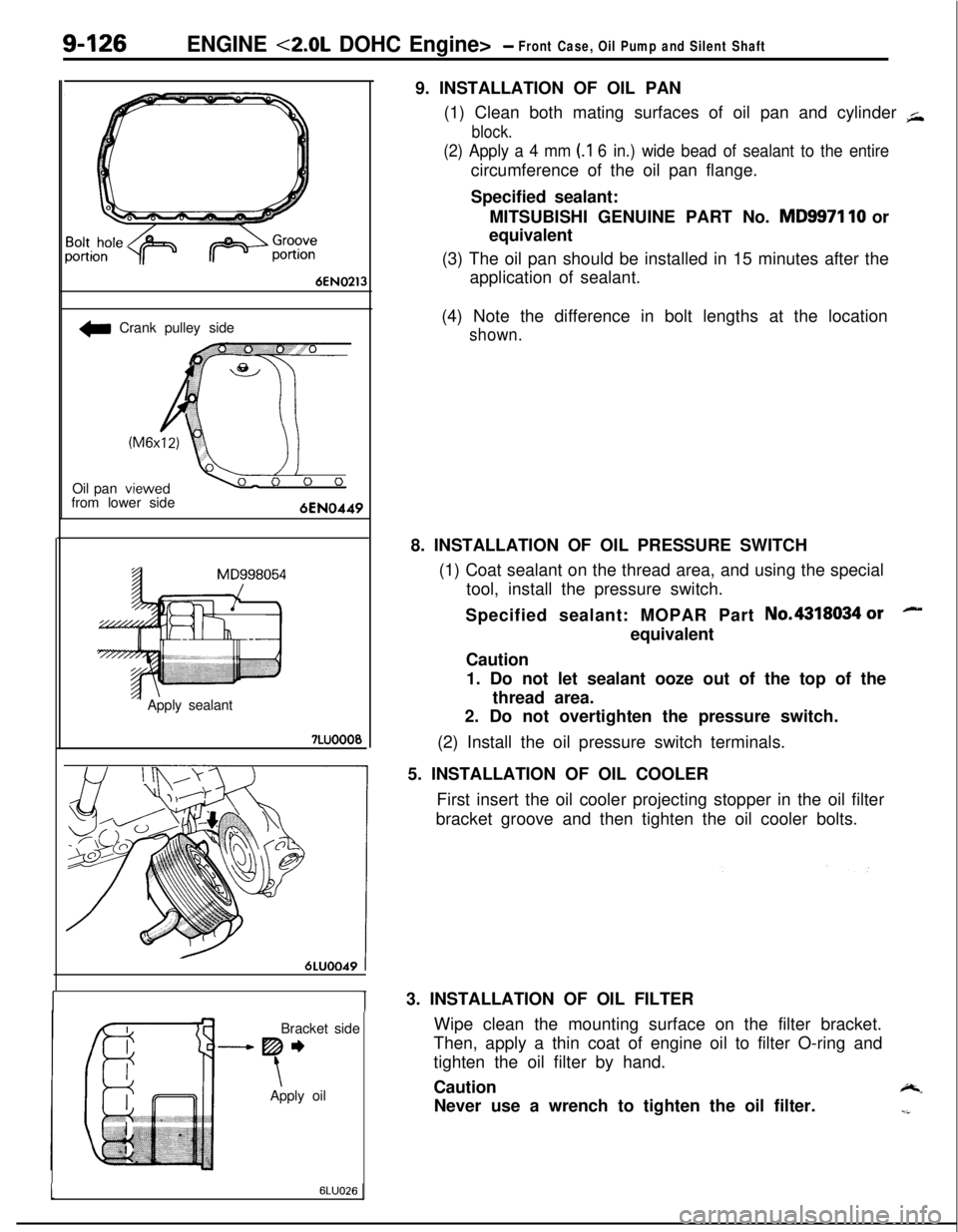
6EN0213
w Crank pulley side
Oil pan
from lower side
‘- Apply sealant7LUOOO0
6LUOO49 tBracket side
-----Be
\Apply oil9. INSTALLATION OF OIL PAN
(1) Clean both mating surfaces of oil pan and cylinder
+
block.
(2) Apply a 4 mm (.I 6 in.) wide bead of sealant to the entirecircumference of the oil pan flange.
Specified sealant:
MITSUBISHI GENUINE PART No.
MD9971 10 or
equivalent
(3) The oil pan should be installed in 15 minutes after the
application of sealant.
(4) Note the difference in bolt lengths at the location
shown.8. INSTALLATION OF OIL PRESSURE SWITCH
(1) Coat sealant on the thread area, and using the special
tool, install the pressure switch.
Specified sealant: MOPAR Part No.4318034
orequivalent
Caution
1. Do not let sealant ooze out of the top of the
thread area.
2. Do not overtighten the pressure switch.
(2) Install the oil pressure switch terminals.
5. INSTALLATION OF OIL COOLER
First insert the oil cooler projecting stopper in the oil filter
bracket groove and then tighten the oil cooler bolts.lu3. INSTALLATION OF OIL FILTER
Wipe clean the mounting surface on the filter bracket.
Then, apply a thin coat of engine oil to filter O-ring and
tighten the oil filter by hand.
Caution
-.Never use a wrench to tighten the oil filter.
-i
16LUO26
Page 411 of 1216
ENGINE <2.0L DOHC Engine> - Piston and Connecting Rod
PISTON AND CONNECTINGRODNonlE-8
cIISASSEMBLY AND REASSEMBLY
6
disassembly steps1. Nut
+e l +2. Connecting rod cap
3. Connecting rod bearing
e+ 4. Piston and connecting rod assembly5. Connecting rod bearing
6. Bolt+e ~~ 7. Piston ring No. 1+e ++ 8. Piston ring No.2
l * 9. Oil ring10. Piston pin11. Piston12. Connecting rod
f86 50-53 Nm36-36 ftlbs.6EN0216
NOTE(1) Reverse the disassembly procedures to reassemble(2) l e : Refer to “Service Points of Disassembly”.(3) +4 : Refer to “Service Points of Reassembly”.
Page 412 of 1216

9-128ENGINE <2.0L DOHC Enaine> - Piston and Connectina Rod
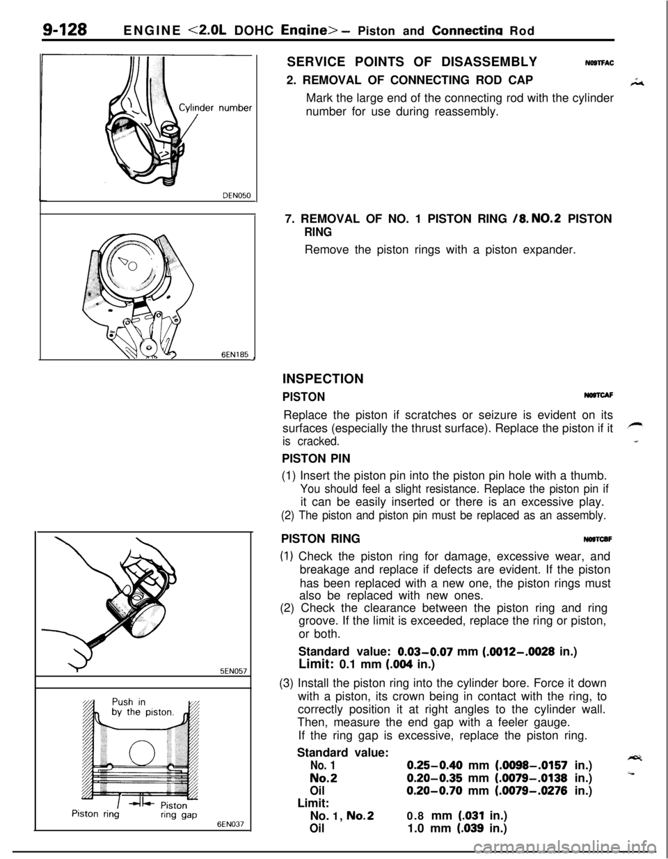
DEN050
6EN185
95EN057
Piston ringring gap6EN037
JSERVICE POINTS OF DISASSEMBLY
NOSTFAC2. REMOVAL OF CONNECTING ROD CAP
Mark the large end of the connecting rod with the cylinder
number for use during reassembly.
7. REMOVAL OF NO. 1 PISTON RING
/8. NO.2 PISTON
RINGRemove the piston rings with a piston expander.
INSPECTION
PISTONNO@lCAFReplace the piston if scratches or seizure is evident on its
surfaces (especially the thrust surface). Replace the piston if it
is cracked.PISTON PIN
(1) Insert the piston pin into the piston pin hole with a thumb.
You should feel a slight resistance. Replace the piston pin ifit can be easily inserted or there is an excessive play.
(2) The piston and piston pin must be replaced as an assembly.PISTON RING
NOSTCBF
(1) Check the piston ring for damage, excessive wear, and
breakage and replace if defects are evident. If the piston
has been replaced with a new one, the piston rings must
also be replaced with new ones.
(2) Check the clearance between the piston ring and ring
groove. If the limit is exceeded, replace the ring or piston,
or both.
Standard value: 0.03-0.07 mm
(.0012-.0028 in.)
Limit: 0.1 mm
(.004 in.)
(3) Install the piston ring into the cylinder bore. Force it down
with a piston, its crown being in contact with the ring, to
correctly position it at right angles to the cylinder wall.
Then, measure the end gap with a feeler gauge.
If the ring gap is excessive, replace the piston ring.
Standard value:
No. 10.25-0.40 mm (.0098-.0157 in.)
No.20.20-0.35 mm (.0079-.0138 in.)
Oil0.20-0.70 mm (.0079-.0276 in.)
Limit:
No. 1,
No.20.8 mm (.031 in.)
Oil1.0 mm (.039 in.)
Page 413 of 1216

ENGINE <2.0L DOHC Engine> - Piston and Connecting Rodgi’1.29
L
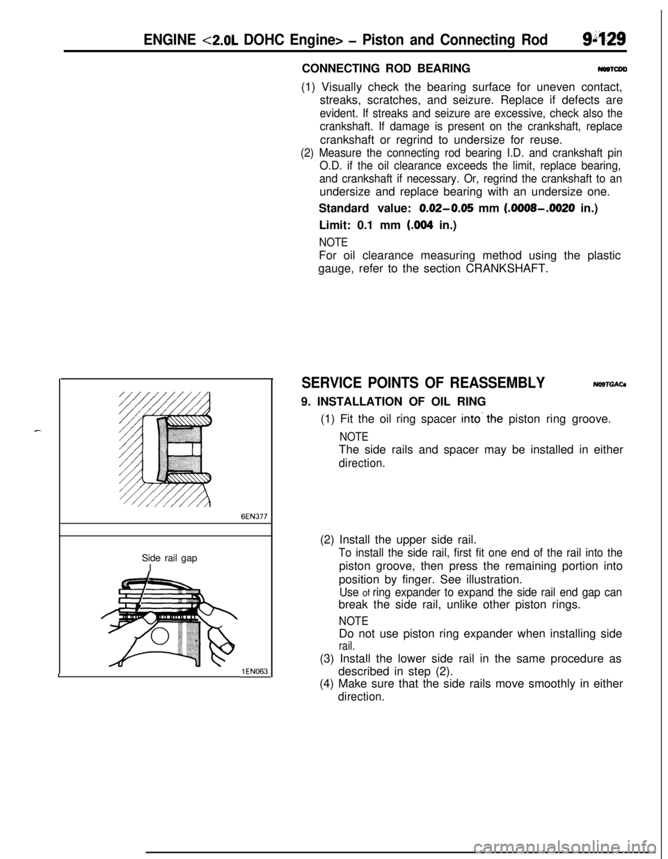
6EN377Side rail gap
I
1 EN062ICONNECTING ROD BEARING
NWTCDD(1) Visually check the bearing surface for uneven contact,
streaks, scratches, and seizure. Replace if defects are
evident. If streaks and seizure are excessive, check also the
crankshaft. If damage is present on the crankshaft, replacecrankshaft or regrind to undersize for reuse.
(2) Measure the connecting rod bearing I.D. and crankshaft pin
O.D. if the oil clearance exceeds the limit, replace bearing,
and crankshaft if necessary. Or, regrind the crankshaft to anundersize and replace bearing with an undersize one.
Standard value:
0.02-0.05 mm (.0008-JO20 in.)
Limit: 0.1 mm
(.004 in.)
NOTEFor oil clearance measuring method using the plastic
gauge, refer to the section CRANKSHAFT.
SERVICE POINTS OF REASSEMBLYNO9TGACa9. INSTALLATION OF OIL RING
(1) Fit the oil ring spacer
into’the piston ring groove.
NOTEThe side rails and spacer may be installed in either
direction.(2) Install the upper side rail.
To install the side rail, first fit one end of the rail into thepiston groove, then press the remaining portion into
position by finger. See illustration.
Use of ring expander to expand the side rail end gap canbreak the side rail, unlike other piston rings.
NOTEDo not use piston ring expander when installing side
rail.(3) Install the lower side rail in the same procedure as
described in step (2).
(4) Make sure that the side rails move smoothly in either
direction.