Page 414 of 1216
9-130ENGINE <2.0L DOHC Engine> - Piston and Connecting Rod
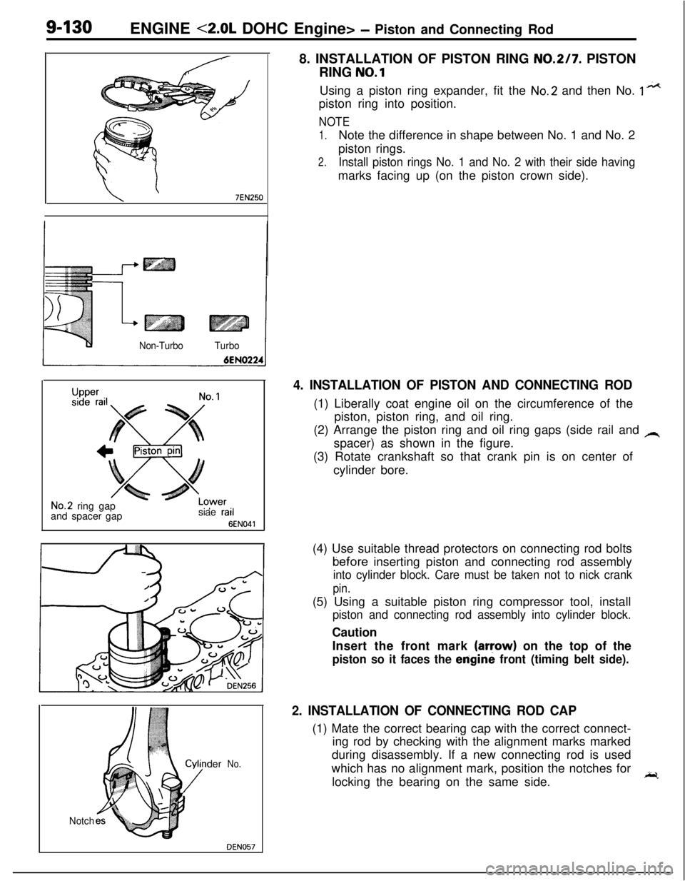
8. INSTALLATION OF PISTON RING
NO.217. PISTON
RING
NO.1
\ ’7EN250
Non-TurboTurbo
Upper
LCsiae rail
6
3wer’ ‘I
EN041
No.2 ring gap
and spacer gap
der
No.
Notch
DEN057Using a piston ring expander, fit the
No.2 and then No. 1 n*tpiston ring into position.
NOTE
1.Note the difference in shape between No. 1 and No. 2
piston rings.
2.Install piston rings No. 1 and No. 2 with their side havingmarks facing up (on the piston crown side).
4. INSTALLATION OF PISTON AND CONNECTING ROD(1) Liberally coat engine oil on the circumference of the
piston, piston ring, and oil ring.
(2) Arrange the piston ring and oil ring gaps (side rail and
Aspacer) as shown in the figure.
(3) Rotate crankshaft so that crank pin is on center of
cylinder bore.
(4) Use suitable thread protectors on connecting rod boltstiefore inserting piston and connecting rod assembly
into cylinder block. Care must be taken not to nick crank
pin.(5) Using a suitable piston ring compressor tool, install
piston and connecting rod assembly into cylinder block.Caution
Insert the front mark
(aryow) on the top of the
piston so it faces the erigine front (timing belt side).
2. INSTALLATION OF CONNECTING ROD CAP(1) Mate the correct bearing cap with the correct connect-
ing rod by checking with the alignment marks marked
during disassembly. If a new connecting rod is used
which has no alignment mark, position the notches for
locking the bearing on the same side.
I;r.
Page 415 of 1216
ENGINE <2.0L DOHC Engine> - Piston and Connecting Rod9-131(2) Check if the thrust clearance in the connecting rod big
end is correct.
Standard value:
0.10-0.25 mm (.0040-.0098 in.)
Limit: 0.4 mm
(.0157in.)
Page 416 of 1216
g-132 ENGINE <2.0L DOHC ‘Engine>- Crankshaft, Flywheel and Drive Plate
CRANKSHAFT, FLYWHEEL AND DRIVE PLATEDISASSEMBLY AND REASSEMBLY
NOBUE-B
1
lo-12 Nm5
7-9 ft.lbs.I
FORWARDIO-12
N/m7-9 ft.lbs.
130-140 Nm94-101 ft.lbs.
I47-51
ftlbs.
130-140 Nm‘94-101 ft.lbs.
6ENO227
Disassembly steps
1. Flywheel (Manual transaxle)
2. Adapter plate3. Drive plateAutomatic
4. Crankshaft bushingtransaxle
5. Rear plate6. Bell housing cover
7. Oil seal case8. Gasket
l + 9. Oil separatorl a 10. Oil seall + 11. Bearing cap
l + 12. Lower bearing
13. Crankshaftl + 14. Upper bearing
NOTE(1) Reverse the disassembly procedures to reassemble.(2) e+ : Refer to “Service Points of Reassembly”.(3) 0 : Non-reusable parts
Page 417 of 1216
ENGINE <2.0L DOHC Engine>- Crankshaft, Flywheel and Drive Plate,91133
INSPECTIONNOSUHAD
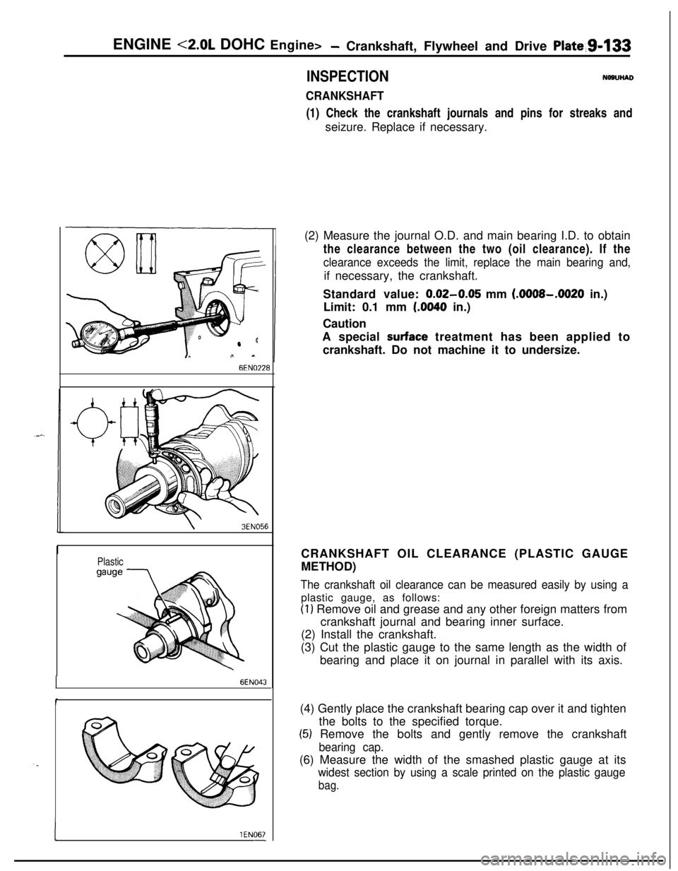
CRANKSHAFT(1) Check the crankshaft journals and pins for streaks and
seizure. Replace if necessary.
6EN0’228
\3EN056
Plastic
6EN043
. .
I1 EN067-(2) Measure the journal O.D. and main bearing I.D. to obtain
the clearance between the two (oil clearance). If the
clearance exceeds the limit, replace the main bearing and,if necessary, the crankshaft.
Standard value:
0.02-0.05 mm (.OOOS-.0020 in.)
Limit: 0.1 mm
(.0040 in.)
Caution
A special
surface treatment has been applied to
crankshaft. Do not machine it to undersize.
CRANKSHAFT OIL CLEARANCE (PLASTIC GAUGE
METHOD)
The crankshaft oil clearance can be measured easily by using aplastic gauge, as follows:
(1) Remove oil and grease and any other foreign matters from
crankshaft journal and bearing inner surface.
(2) Install the crankshaft.
(3) Cut the plastic gauge to the same length as the width of
bearing and place it on journal in parallel with its axis.
(4) Gently place the crankshaft bearing cap over it and tighten
the bolts to the specified torque.
(5) Remove the bolts and gently remove the crankshaft
bearing cap.(6) Measure the width of the smashed plastic gauge at its
widest section by using a scale printed on the plastic gauge
bag.
Page 418 of 1216
g-134 ENGINE <2.0L DOHC Engine>- Crankshaft, Flywheel and Drive Plate
3EN301CRANKSHAFT REAR OIL SEAL
(1) Check oil seal lip for wear and damage.
(2) Check rubber for deterioration or hardening.
(3) Check oil seal case for cracks and damage.
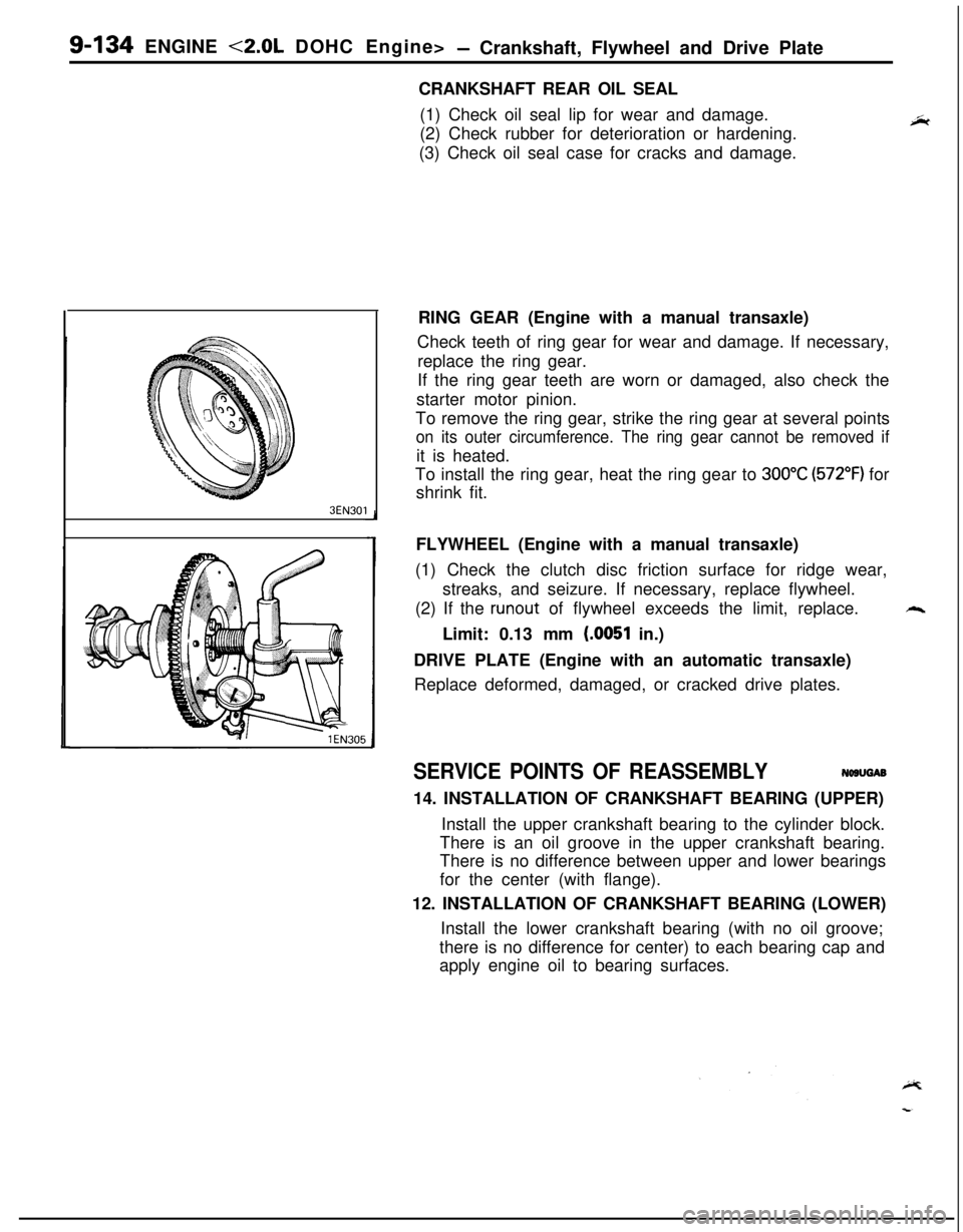
RING GEAR (Engine with a manual transaxle)
Check teeth of ring gear for wear and damage. If necessary,
replace the ring gear.
If the ring gear teeth are worn or damaged, also check the
starter motor pinion.
To remove the ring gear, strike the ring gear at several points
on its outer circumference. The ring gear cannot be removed ifit is heated.
To install the ring gear, heat the ring gear to
300°C (572°F) for
shrink fit.
FLYWHEEL (Engine with a manual transaxle)
(1) Check the clutch disc friction surface for ridge wear,
streaks, and seizure. If necessary, replace flywheel.
(2) If the
runout of flywheel exceeds the limit, replace.++.Limit: 0.13 mm
(.0051 in.)
DRIVE PLATE (Engine with an automatic transaxle)
Replace deformed, damaged, or cracked drive plates.
SERVICE POINTS OF REASSEMBLYNWUGAB
14. INSTALLATION OF CRANKSHAFT BEARING (UPPER)
Install the upper crankshaft bearing to the cylinder block.
There is an oil groove in the upper crankshaft bearing.
There is no difference between upper and lower bearings
for the center (with flange).
12. INSTALLATION OF CRANKSHAFT BEARING (LOWER)
Install the lower crankshaft bearing (with no oil groove;
there is no difference for center) to each bearing cap and
apply engine oil to bearing surfaces.
Page 419 of 1216
ENGINE <2.0L DOHC Engine> -Crankshaft, Flywheel and Drive Plate g-135
‘I. _
Front ofengine
(Timing
belt side)
BEN02
DEN063
6ENO48-
11. INSTALLATION OF BEARING CAP
(1) Verify the correct identification mark and the directionof the arrow for installation.
(2) After installing the bearing caps, make sure that the
crankshaft turns smoothly and the end play is correct. Ifthe end play exceeds the limit, replace crankshaft
bearings.Standard value:
0.05-0.18 mm (.0020-.0071 in.)
Limit: 0.25 mm
(.0098 in.)
10. INSTALLATION OF OIL SEALUsing the special tool, press-fit the oil seal into the
crankshaft rear oil case. Use a new oil seal.9. INSTALLATION OF OIL SEPARATOR
Force the oil separator into the oil seal case so that the oilhole in the separator is directed downward (arrow in
illustration).
Page 420 of 1216
9-136ENGINE <2.0L DOHC Engine> - Cylinder Block
CYLINDER BLOCK
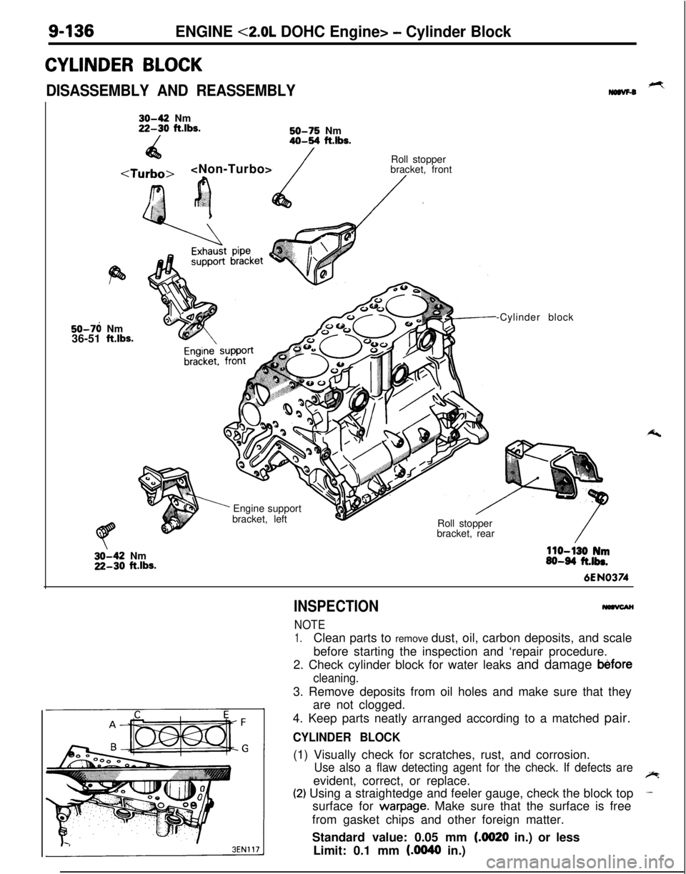
DISASSEMBLY AND REASSEMBLY,+Ymaw-030-42 Nm22-30 ft.lbs.
/50-75 Nm40-54 ft.lbs.
4a
/
r.‘?’
’ cRoll stopper
bracket, front/.50-76 Nm
36-51
ftlbs.
’ Engine support
bracket, left
Roll stopper
bracket, rear-Cylinder block32-42 Nm22-30
ftlbs.
110-130 Nm60-64 ft.lbs.6EN0374
INSPECTION
NOTE
1.Clean parts to remove dust, oil, carbon deposits, and scale
before starting the inspection and ‘repair procedure.
2. Check cylinder block for water leaks and damage
b&fore
cleaning.3. Remove deposits from oil holes and make sure that they
are not clogged.
4. Keep parts neatly arranged according to a matched pair.
CYLINDER BLOCK(1) Visually check for scratches, rust, and corrosion.
Use also a flaw detecting agent for the check. If defects areevident, correct, or replace.~
(2) Using a straightedge and feeler gauge, check the block top-surface for
warpage. Make sure that the surface is free
from gasket chips and other foreign matter.
Standard value: 0.05 mm
(4020 in.) or less
Limit: 0.1 mm
(AM40 in.)
Page 421 of 1216
ENGINE <2.0L DOHC Engine> - Cylinder Block9437
Thrustdirection
6EN054-(3) If the distortion is excessive, correct within the allowable
limit or replace.
Grinding limit: 0.2 mm
(008 in.)
The total thickness of the stock allowed to be
removed from cylinder block and mating cylinder
head is 0.2 mm
(008 in.) at maximum.
Cylinder block height (when new): 284 mm (11.18 in.)
(4) Check cylinder walls for scratches and seizure. If defects
are evident, correct (bored to oversize) or replace.
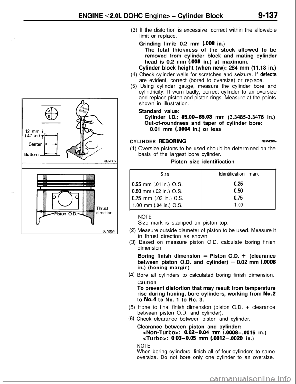
(5) Using cylinder gauge, measure the cylinder bore and
cylindricity. If worn badly, correct cylinder to an oversize
and replace piston and piston rings. Measure at the points
shown in illustration.
Standard value:
Cylinder I.D.:
85.00-85.03 mm (3.3485-3.3476 in.)
Out-of-roundness and taper of cylinder bore:
0.01 mm
(6064 in.) or less
CYLINDER REBORINGNO9VEDCa(1) Oversize pistons to be used should be determined on the
basis of the largest bore cylinder.
Piston size identification
Size0.25 mm
(.Ol in.) O.S.
0.50 mm
(.02 in.) O.S.
0.75 mm
(.03 in.) OS.
1.00 mm LO4 in.) O.S.
Identification mark0.25
0.50
0.75
1 .oo
NOTESize mark is stamped on piston top.
(2) Measure outside diameter of piston to be used. Measure it
in thrust direction as shown.
(3) Based on measure piston O.D. calculate boring finish
dimension.Boring finish dimension
= Piston O.D. + (clearance
between piston O.D. and cylinder)
- 0.02 mm (.OOOSin.) (honing margin)
(4) Bore all cylinders to calculated boring finish dimension.
CautionTo prevent distortion that may result from temperature
rise during honing, bore cylinders, working from
No.2to No.4 to No. 1 to No. 3.
(5) Hone to final finish dimension (piston O.D. + clearance
between piston O.D. and cylinder).
(6) Check clearance between piston and cylinder.
Clearance between piston and cylinder:
:
0.02-064 mm (AMOS-,001~ in.)
:
0.03-0.05 mm (.OOW-.O020 in.)
NOTEWhen boring cylinders, finish all of four cylinders to same
oversize. Do not bore only one cylinder to an oversize.