1991 MITSUBISHI ECLIPSE engine
[x] Cancel search: enginePage 423 of 1216

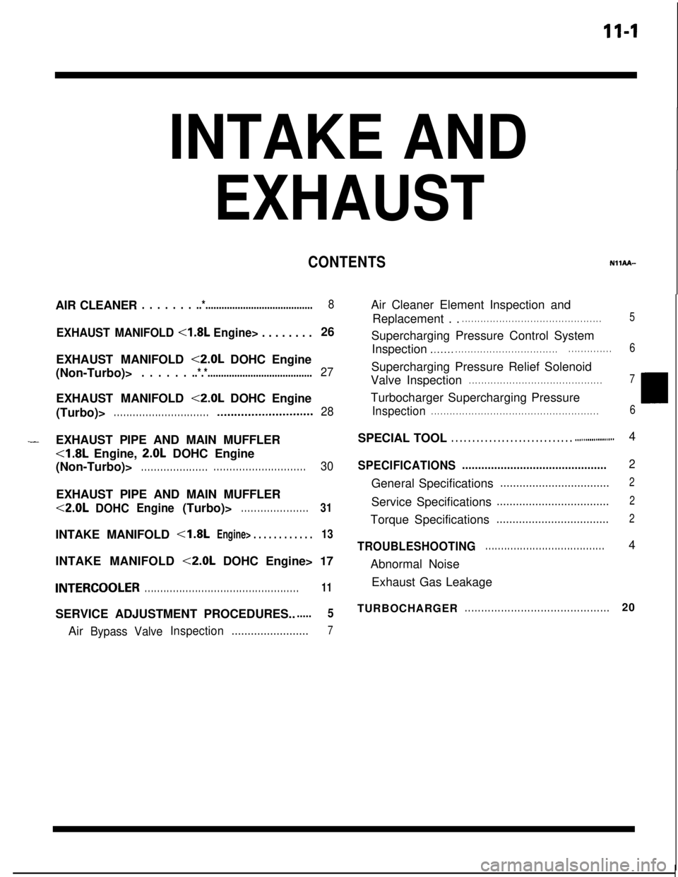
11-l
INTAKE AND
EXHAUSTAIR CLEANER
. . . . . . . ..*........................................8
EXHAUST MANIFOLD <1.8L Engine> . . . . . . . .26
EXHAUST MANIFOLD
<2.0L DOHC Engine
(Non-Turbo)>
. . . . . . ..*.*.......................................27EXHAUST MANIFOLD
<2.0L DOHC Engine
(Turbo)>
. . . . . . . . . . . . . . . . . . . . . . . . . . . . . .*...........................28
CONTENTSNllAA--
-EXHAUST PIPE AND MAIN MUFFLER<1.8L Engine,
2.0L DOHC Engine
(Non-Turbo)>
. . . . . . . . . . . . . . . . . . . . .. . . . . . . . . . . . . . . . . . . . . . . . . . . . .30EXHAUST PIPE AND MAIN MUFFLER<2.0L
DOHCEngine(Turbo)>. . . . . . . . . . . . . . . . . . . . .31INTAKE MANIFOLD
<1.8LEngine> . . . . . . . . . . . .13INTAKE MANIFOLD
<2.0L DOHC Engine> 17
INTERCOOLER. . . . . . . . . . . . . . . . . . . . . . . . . . . . . . . . . . . . . . . . . . . . . . . . .11SERVICE ADJUSTMENT PROCEDURES..
.....5Air
Bypass ValveInspection........................7Air Cleaner Element Inspection and
Replacement . .
. . . . . . . . . . . . . . . . . . . . . . . . . . . . . . . . . . . . . . . . . . . . .5Supercharging Pressure Control System
Inspection
.,...... . . . . . . . . . . . . . . . . . . . . . . . . . . . . . . . .. . . . . . . . . . . . . .6Supercharging Pressure Relief Solenoid
Valve Inspection
. . . . . . . . . . . . . . . . . . . . . . . . . . . . . . . . . . . . . . . . . . .7Turbocharger Supercharging Pressure
Inspection. . . . . . . . . . . . . . . . . . . . . . . . . . . . . . . . . . . . . . . . . . . . . . . . . . . . . .6SPECIAL TOOL
. . . . . . . . . . . . . . . . . . . . . . . . . . . . . ..#................4
SPECIFICATIONS.............................................2General Specifications
..................................2Service Specifications
...................................2Torque Specifications
...................................2
TROUBLESHOOTING. . . . . . . . . . . . . . . . . . . . . . . . . . . . . . . . . . . . . .4
Abnormal Noise
Exhaust Gas Leakage
TURBOCHARGER
. . . . . . . . . . . . . . . . . . . . . . . . . . . . . . . . . . . . . . . . . . . .20
Page 425 of 1216

--
INTAKE AND EXHAUST - SDecificationsII-3
ItemsIntake manifold
<1.8L Engine>
Accelerator cable to air intake plenum
Fuel high pressure hose to delivery pipe
Delivery pipe to intake manifold
Intake manifold stay
Engine hanger
Intake manifold to engine
Throttle body
Air intake plenum stay
Air intake plenum to intake manifold
Water outlet fitting
EGR valveEGR temperature sensor
Ground cable to air intake plenum
Control harness protector to air intake plenum
CoverIntake manifold
<2.0L DOHC Engine>
Accelerator cable to intake manifold
Throttle body stay
Fuel high pressure hose to delivery pipe
Delivery pipe to engine
Intake manifold stay
Intake manifold to engine
Mounting bolt
(M8)Mounting nut and bolt (MIO)
Ignition coil
Power transistor unit
Throttle body
EGR valveEGR temperature sensor
Control harness protector to intake manifold
Control harness clamp bolt
ixhaust manifold
<1.8L Engine>
Front exhaust pipe to exhaust manifold
Front exhaust pipe to engine
Exhaust manifold cover (A) to exhaust manifold
Exhaust manifold cover (B) to exhaust manifold
Exhaust manifold cover (A) to exhaust manifold cover (B)
Exhaust manifold to engine
Oxygen sensor
Engine oil level gauge guide mounting bolt
ixhaust manifold
<2.0L DOHC Engine (Non-Turbo)>
Front exhaust pipe to exhaust manifold
Front exhaust pipe to engine
Heat protector (A), (B)
Exhaust manifold to engine
Oxygen sensor
Engine hanger to engine
ixhaust manifold and turbocharger
<2.0L DOHC Engine (Turbo)>
Front exhaust pipe to exhaust fitting
Front exhaust pipe to engine
Heat protector (A),
(B)
Nmft.lbs.
4-6
3-4
4-6
3-4
IO-137-9
18-25
13-18
15-20II-14
15-2011-14
15-22II-16
15-2011-14
15-2011-14
17-2012-14
IO-157-11
IO-127-9
10-127-9
4-6
3-4
IO-137-9
4-6
3-4
15-22
11-16
4-6
3-4
IO-137-9
25-3018-22
15-2011-14
30-4222-30
20-2714-20
IO-127-9
15-22
11-16
15-22II-16
IO-127-9
4-6
3-4
IO-127-9
30-4022-29
30-4022-29
27-33
20-24
20-2814-20
8-106-7
15-2011-14
40-5029-36
12-15
9-l 1
30-4022-29
30-4022-29
12-15
9-l 1
25-3018-22
40-5029-36
12-15
9-l 1
40-6029-43
30-4022-29
12-15
9-11
Page 426 of 1216

11-4INTAKE AND EXHAUST- Specifications/Special Tool/Troubleshooting
ItemsEngine oil level gauge guide mounting bolt
Engine hanger to engine
Exhaust manifold to engine
Exhaust manifold to turbocharger
Oil pipe to engine
Water pipe
(B) to water inlet pipe
Waste gate actuator
Oxygen sensor
Water pipe
(B) to turbocharger
Air outlet fitting
Oil pipe to turbocharger
Water pipe (A) to turbocharger
Water pipe (A) mounting bolt
Exhaust fitting
Oil return pipe
Exhaust pipe and main muffler
Front exhaust pipe to exhaust manifold
Front exhaust pipe to exhaust fitting
Front exhaust pipe clamp
Rubber hangerFront exhaust pipe to catalytic converter
Catalytic converter to center exhaust pipe
Hanger bracket to body
Hook to center exhaust pipe
Center exhaust pipe to main muffler
Moulding to main muffler
Nmft.lbs.
12-15
9-l 112-159-11
25-3018-?255-65
40-4714-19
IO-l+
40-5029-36
IO-137-9
40-5029-36
35-5025-36
9-14
7-1028-34
20-25
35-5025-36
IO-127-9
55-65
40-47
8-106-7
30-4022-29
40-6029-43
30-4022-29
IO-157-11
40-6029-43
30-4022-29
10-157-11
10-157-11
30-4022-29
4-63-4
TROUBLESHOOTINGNllEAAB
Symptom
Exhaust gas leakage
Abnormal noiseProbable cause
Loose joints
Broken pipe or muffler
Broken separator in muffler
Broken rubber hangersInterference of pipe or muffler with vehicle body
Broken pipe or mufflerRemedy
Retighten
Repair or replace
Replace
Correct
Repair or replace
.-*
SPECIAL TOOLNllDA-
I ToolNumberNameI UseIRemoval/Installation of oxygen sensor
Removal/Installation of oxygen sensor
Fs\
Page 427 of 1216

INTAKE AND EXHAUST - Service Adjustment Procedures11-5
SERVICE ADJUSTMENT PROCEDURES
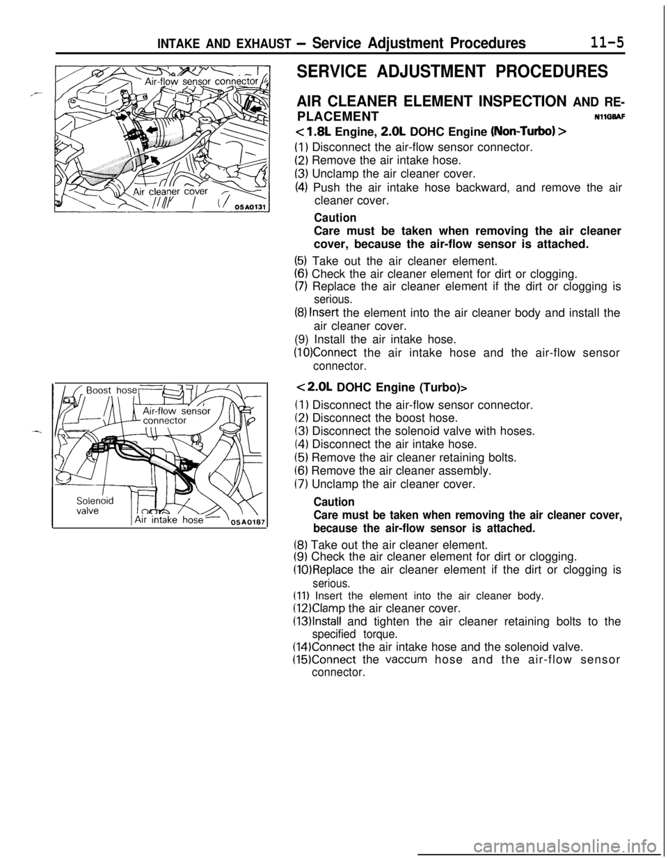
AIR CLEANER ELEMENT INSPECTION AND RE-PLACEMENTNllQBAF
< 1.8L Engine, 2.0L DOHC Engine (Non-Turbo) >
(1) Disconnect the air-flow sensor connector.
(2) Remove the air intake hose.
(3) Unclamp the air cleaner cover.
(4) Push the air intake hose backward, and remove the air
cleaner cover.
CautionCare must be taken when removing the air cleaner
cover, because the air-flow sensor is attached.
(5) Take out the air cleaner element.
(6) Check the air cleaner element for dirt or clogging.
(7) Replace the air cleaner element if the dirt or clogging is
serious.
(8) Insert the element into the air cleaner body and install the
air cleaner cover.
(9) Install the air intake hose.
(10)Connect the air intake hose and the air-flow sensor
connector.
<2.0L DOHC Engine (Turbo)>(I
1 Disconnect the air-flow sensor connector.
(2) Disconnect the boost hose.
(3) Disconnect the solenoid valve with hoses.
(4) Disconnect the air intake hose.
(5) Remove the air cleaner retaining bolts.
(6) Remove the air cleaner assembly.
(7) Unclamp the air cleaner cover.
Caution
Care must be taken when removing the air cleaner cover,
because the air-flow sensor is attached.
(8) Take out the air cleaner element.
(9) Check the air cleaner element for dirt or clogging.
(10)Replace the air cleaner element if the dirt or clogging is
serious.
(11) Insert the element into the air cleaner body.
(12)Clamp the air cleaner cover.
(13)lnstall and tighten the air cleaner retaining bolts to the
specified torque.
(14)Connect the air intake hose and the solenoid valve.
(15)Connect the vaccum hose and the air-flow sensor
connector.
Page 428 of 1216

11-6INTAKE AND EXHAUST - Service Adjustment Procedwes
Wasie gate actuator05AOlSO
TURBOCHARGER SUPERCHARGING PRESSURE
INSPECTIONN1mAAB!PTCautionPerform running inspection with two passengers in the
-’vehicle and where full throttle acceleration can be safely
made.The pressure gauge reading is taken by a front seat
passenger.
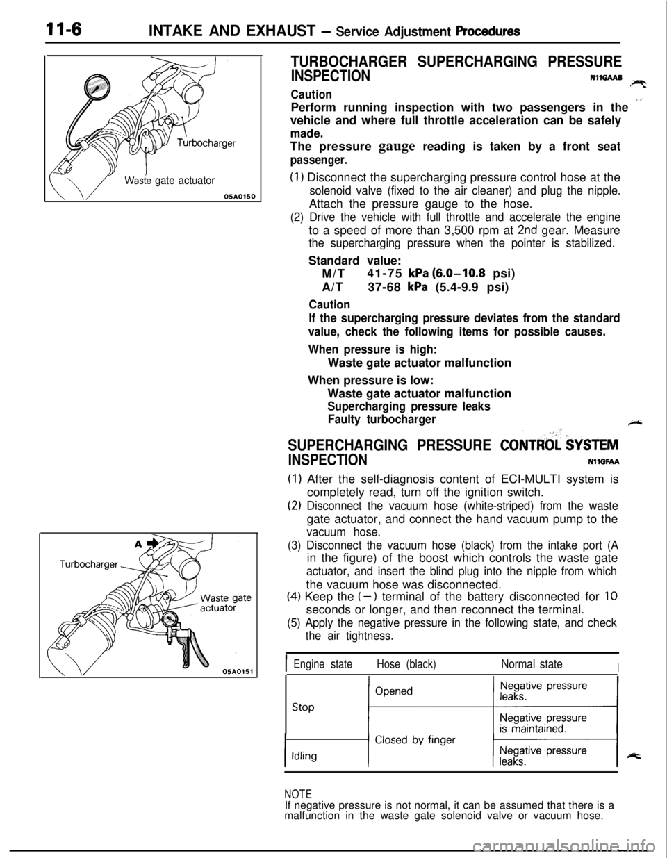
(1) Disconnect the supercharging pressure control hose at the
solenoid valve (fixed to the air cleaner) and plug the nipple.Attach the pressure gauge to the hose.
(2) Drive the vehicle with full throttle and accelerate the engineto a speed of more than 3,500 rpm at
2nd gear. Measure
the supercharging pressure when the pointer is stabilized.Standard value:
M/T41-75
kPa (6.0-10.8 psi)
A/T37-68
kPa (5.4-9.9 psi)
Caution
If the supercharging pressure deviates from the standard
value, check the following items for possible causes.
When pressure is high:Waste gate actuator malfunction
When pressure is low:
Waste gate actuator malfunction
Supercharging pressure leaks
Faulty turbocharger
+-
SUPERCHARGING PRESSURE CONTRtd $YSTEM
INSPECTIONNllGFAA
(1) After the self-diagnosis content of ECI-MULTI system is
completely read, turn off the ignition switch.
(2) Disconnect the vacuum hose (white-striped) from the wastegate actuator, and connect the hand vacuum pump to the
vacuum hose.
(3) Disconnect the vacuum hose (black) from the intake port (Ain the figure) of the boost which controls the waste gate
actuator, and insert the blind plug into the nipple from whichthe vacuum hose was disconnected.
(4) Keep the (- ) terminal of the battery disconnected for 10seconds or longer, and then reconnect the terminal.
(5) Apply the negative pressure in the following state, and check
the air tightness.
IEngine stateHose (black)Normal stateI
stop ;“““*I
NOTEIf negative pressure is not normal, it can be assumed that there is a
malfunction in the waste gate solenoid valve or vacuum hose.
Page 429 of 1216

INTAKE AND EXHAUST - Service Adjustment ProceduresII-7
w05A0155
h61
NO06061
NO0616 I
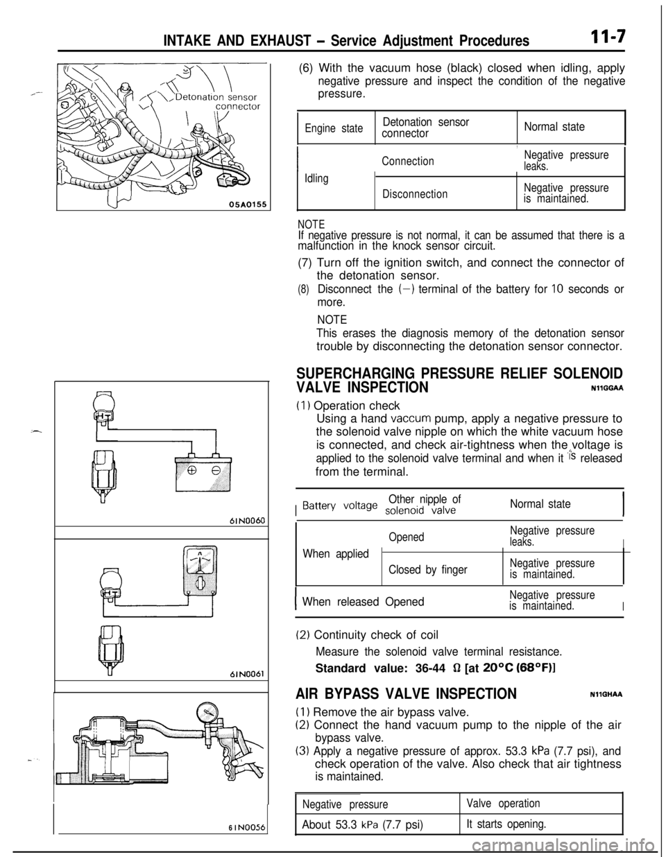
NO056(6) With the vacuum hose (black) closed when idling, apply
negative pressure and inspect the condition of the negative
pressure.
Engine stateDetonation sensor
connectorNormal state
,
ConnectionNegative pressureleaks.
Idling
DisconnectionNegative pressure
is maintained.
NOTEIf negative pressure is not normal, it can be assumed that there is amalfunction in the knock sensor circuit.(7) Turn off the ignition switch, and connect the connector of
the detonation sensor.
(8)Disconnect the (-) terminal of the battery for 10 seconds or
more.
NOTE
This erases the diagnosis memory of the detonation sensortrouble by disconnecting the detonation sensor connector.
SUPERCHARGING PRESSURE RELIEF SOLENOID
VALVE INSPECTIONNllGGAA
(1) Operation check
Using a hand
vaccum pump, apply a negative pressure to
the solenoid valve nipple on which the white vacuum hose
is connected, and check air-tightness when the voltage is
applied to the solenoid valve terminal and when it i‘s releasedfrom the terminal.
I
Other nipple ofBattery voile solenoid valveNormal state
OpenedNegative pressureleaks.IWhen applied
Closed by fingerNegative pressure
is maintained.
IWhen released OpenedNegative pressure
is maintained.
I
(2) Continuity check of coil
Measure the solenoid valve terminal resistance.Standard value: 36-44
fl [at 20°C (68OF)l
AIR BYPASS VALVE INSPECTIONNllGHAA
(1) Remove the air bypass valve.
(2) Connect the hand vacuum pump to the nipple of the air
bypass valve.
(3) Apply a negative pressure of approx. 53.3 kPa (7.7 psi), andcheck operation of the valve. Also check that air tightness
is maintained.
Negative pressure
About 53.3 kPa (7.7 psi)
Valve operation
It starts opening.
Page 430 of 1216

II-8INTAKE AND EXHAUST - Air Cleaner
AIR CLEANERREMOVAL AND INSTALLATION
< 1.8L Engine, 2.0L DOHC Engine (Non-Turbo) >
NllFA- -%
8-10 Nm
6-7 ft.1bs.y ’
LJ
*l
<2.0L DOHC Engine (Non-Turbo)>IO-13 Nm
7-9
ft.lbs.
18
9
80
05AO1374
05A0179
05A0140Removal steps1. Connection for air flow sensor
connector
2.Breather hose3. Air intake hose
4.Air cleaner
5. Air cleaner cover
6. Air cleaner element
7. Air flow sensor assembly
8. Air flow sensor gasket
9. Noise reduction filter
10.Cover11.Grommet12. Air cleaner body
13.Insulator14.Collar
15.Packing
16.Tuning pipe
17. Splash shield extension
18.Resonator
NOTE(I) Reverse the removal procedures to reinstall.(2) q : Non-reusable parts*I: <1.8L engine>*2: <2.0L DOHC engine (Non-Turbo)>
Page 431 of 1216

INTAKE AND EXHAUST - Air Cleaner
REMOVAL AND INSTALLATION
<2.0L DOHC Engine (Turbo)>
II-S
8-10 Nm6-7, ft.lbs.12-15 Nm9- 11 ftlbs.
/
8
18
05AO167
605A0182
Removal steps
1. Air pipe
B2. By-pass air hose3. Connection for air flow sensor
connector
4.Vacuum hose
5. Waste gate solenoid valve
6.Breather hose7.Purge hose8.Air cleaner9. Air intake hose
10. Air cleaner bracket11. Air cleaner cover
12. Air cleaner element13. Air flow sensor assembly
14. Air flow sensor gasket
15. Noise reduction filter
16.Cover17.Grommet
18. Air cleaner body
19.Insulator20.Collar
NOTE(1) Reverse the removal procedures to reinstall.(2) q : Non-reusable parts