Page 398 of 1216
9-114ENGINE <2.0L DOHC Engine> - Cylinder Head and Valve
Ridgewear
1 EN034Contact with
valve seat
(to be at center
6EN020
I
Freeheight
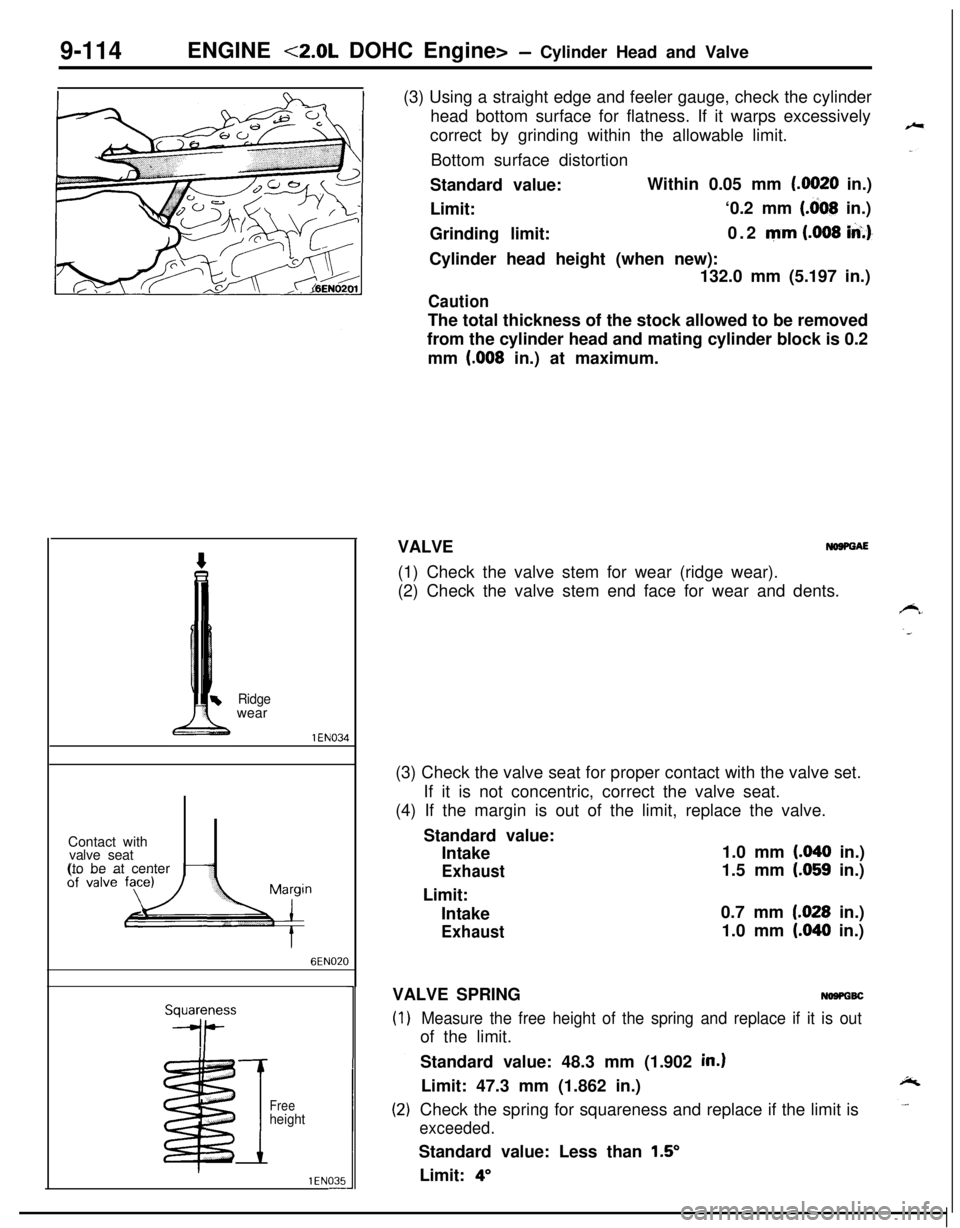
1 EN035-(3) Using a straight edge and feeler gauge, check the cylinder
head bottom surface for flatness. If it warps excessively
correct by grinding within the allowable limit.
Bottom surface distortion
Standard value:Within 0.05 mm
(.0020 in.)
Limit:‘0.2 mm
(.dO8 in.)
Grinding limit:0.2 mm
(.008 iA.)-Cylinder head height (when new):
132.0 mm (5.197 in.)
CautionThe total thickness of the stock allowed to be removed
from the cylinder head and mating cylinder block is 0.2
mm
(.008 in.) at maximum.
VALVE
NOSPGAE(1) Check the valve stem for wear (ridge wear).
(2) Check the valve stem end face for wear and dents.
(3) Check the valve seat for proper contact with the valve set.
If it is not concentric, correct the valve seat.
(4) If the margin is out of the limit, replace the valve.
Standard value:
Intake1.0 mm
(.040 in.)
Exhaust1.5 mm (.059 in.)
Limit:
Intake0.7 mm
1.028 in.)
Exhaust1.0 mm (.040 in.)
VALVE SPRING
NOSPGBC
Measure the free height of the spring and replace if it is outof the limit.
Standard value: 48.3 mm (1.902
in.)Limit: 47.3 mm (1.862 in.)
Check the spring for squareness and replace if the limit is
exceeded.Standard value: Less than
1.5’Limit:
4”
Page 399 of 1216
ENGINE <2.0L DOHC Engine> - Cylinder Head and Valve9-115
1Ghde I.D.
Guide O.D.
1 EN298
Valve
ispring
*seat
\ Iril
: :
MD998737
Valvestem
seal
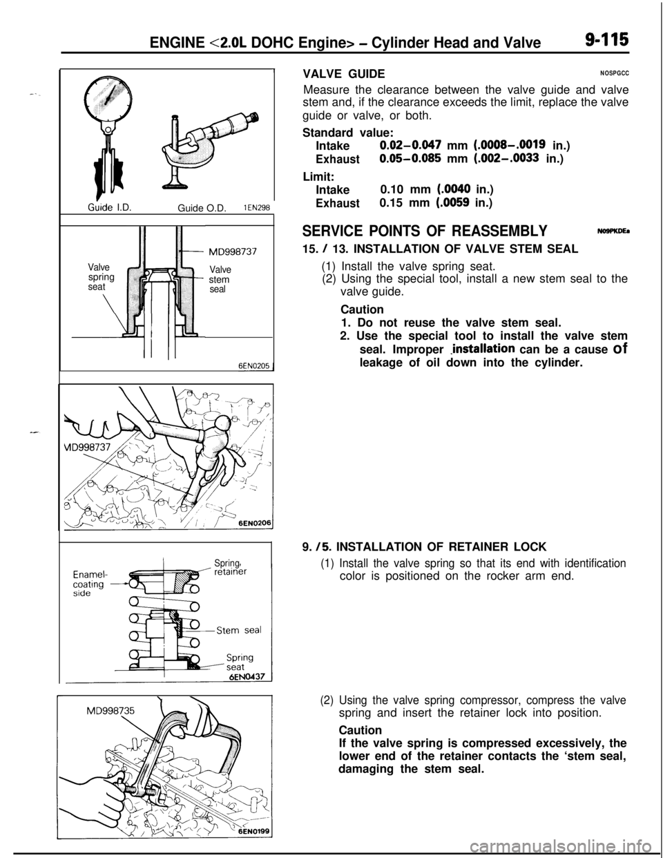
SpringVALVE GUIDE
NOSPGCCMeasure the clearance between the valve guide and valve
stem and, if the clearance exceeds the limit, replace the valve
guide or valve, or both.
Standard value:
Intake
0.02-0.047 mm (.OOOS-.0019 in.)
Exhaust0.05-0.085 mm (.002-.0033 in.)
Limit:
Intake0.10 mm
(.0040 in.)
Exhaust0.15 mm (.0059 in.)
SERVICE POINTS OF REASSEMBLYNoaPKDEa15.
/ 13. INSTALLATION OF VALVE STEM SEAL
(1) Install the valve spring seat.
(2) Using the special tool, install a new stem seal to the
valve guide.
Caution
1. Do not reuse the valve stem seal.
2. Use the special tool to install the valve stem
seal. Improper
Jnstallation can be a cause of
leakage of oil down into the cylinder.
9.
/5. INSTALLATION OF RETAINER LOCK
(1) Install the valve spring so that its end with identificationcolor is positioned on the rocker arm end.
(2) Using the valve spring compressor, compress the valvespring and insert the retainer lock into position.
Caution
If the valve spring is compressed excessively, the
lower end of the retainer contacts the ‘stem seal,
damaging the stem seal.
Page 400 of 1216
9416
I
ENGINE <2.0L DOHC Engine> - Cylinder Head and Valve
I1. INSTALLATION OF CYLINDER HEAD BOLTS
(1) Using the special tool, tighten the cylinder head bolts.
G Front of engine (Timing belt side)(2) Tighten the cylinder head bolts in the sequence shown.
Each bolt should be tightened in two to three steps,
torquing progressively. Tighten to specified torque in
the final sequence.
Page 401 of 1216

ENGINE <2.0L DOHC Engine> -Front Case, Oil Pump and Silent Shaft9-117
FRONT CASE, OIL PUMP AND SILENT SHAFT
DISASSEMBLY AND REASSEMBLY
40-45 Nm29-33 ft.lbs.
\
32
I
NOSRF-B11-13
ft.lbs.
LO8-12 Nm6-9 ft.lbs.\
\715-22 Nm -11-16 ft.lbs.,15-22
Nm11-16 ft.lbs.
Disassembly steps
I. Drain pluo
\/‘16EN046835-45
Nm25-33 ft.lbs.2.Gasket-l + 3. Oil filter
4. Oil cooler bolt (Turbo)
~~ 5. Oil cooler (Turbo)
6. Oil pressure switch
7.Harness assembly8. Oil pressure gauge unit
9.Oil pan10.Oil screen
11.Gasket12. Oil filter bracket
13.Gasket14.Relief plug
15.Gasket16.Relief spring17.Relief plunger
l 4 23. Oil seall + 24. Silent shaft oil seall + 25. Crankshaft front oil seal26. Oil pump cover
l * 27. Oil pump driven geare+ 28. Oil pump drive gear
29. Left silent shaft
30. Right silent shaft
W W 31. Silent shaft front bearings
W W 32. Right silent shaft rear bearing
~~ ~~ 33. Left silent shaft rear bearing34. Check valve (Turbo)
35. Gasket (Turbo)
l + 36. Oil jet (Turbo)37. Gasket (Turbo)
l I) W 18. Plug cap-NOTE19. O-ring(1) Reverse the disassembly procedures to reassemble.+e I)+ 20. Driven gear bolt(2) 4I) : Refer to “Service Points of Disassembly”.
I)+ 21. Front case(3) ~~ : Refer to “Service Points of Reassembly”.
22. Gasket(4) m : Non-reusable parts
Page 402 of 1216
9-118ENGINE <2.0L DOHC Engine>- Front Case, Oil Pump and Silent Shaft
7LUOOO5
I_ MD998727_ MD998727SERVICE POINTS OF DISASSEMBLY
NOIROA~U6. REMOVAL OF OIL PRESSURE SWITCH
(1) Remove the oil pressure switch terminals.
(2) Using the special tool, remove the oil pressure switch.
CautionSince sealant is coated on the thread area, be
careful not to break it.
9. REMOVAL OF OIL PAN
(1) Remove the all oil pan bolts.
(2) Drive in the special tool between the cylinder block and
oil pan.
NOTE
Never use a screwdriver or chisel, instead of the special
tool, as a deformed oil pan flange will result, resulting inoil leakage.
18. REMOVAL OF PLUG CAP
Using the special tool, remove the plug cap.
20. REMOVAL OF DRIVEN GEAR BOLT
(1) Remove the plug on the side of cylinder block.
(2) Insert a Phillips screwdriver [shank diameter 8 mm
(.32in.)] into the plug hold to block the silent shaft.
(3) Remove the driven gear bolt that secures the oil pump
driven gear to the silent shaft.
Page 403 of 1216
ENGINE <2.0L DOHC Engine>- Front Case, Oil Puma and Silent Shaft9419
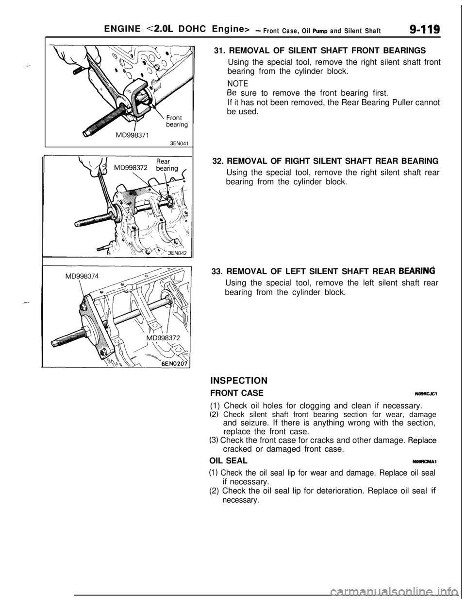
3EN04131. REMOVAL OF SILENT SHAFT FRONT BEARINGS
Using the special tool, remove the right silent shaft front
bearing from the cylinder block.
NOTE
Be sure to remove the front bearing first.
If it has not been removed, the Rear Bearing Puller cannot
be used.
32. REMOVAL OF RIGHT SILENT SHAFT REAR BEARING
Using the special tool, remove the right silent shaft rear
bearing from the cylinder block.
33. REMOVAL OF LEFT SILENT SHAFT REAR
BEARINGUsing the special tool, remove the left silent shaft rear
bearing from the cylinder block.
INSPECTION
FRONT CASE
NOSRCJCl(1) Check oil holes for clogging and clean if necessary.
(2) Check silent shaft front bearing section for wear, damage
and seizure. If there is anything wrong with the section,
replace the front case.
(3) Check the front case for cracks and other damage. Repladecracked or damaged front case.
OIL SEAL
NOSRCMAl
(1) Check the oil seal lip for wear and damage. Replace oil sealif necessary.
(2) Check the oil seal lip for deterioration. Replace oil seal
!if
necessary.
Page 404 of 1216
9-120ENGINE <2.0L DOHC Engine>- Front Case, Oil Pump and Silent Shaft
7LUOoo6
Fine
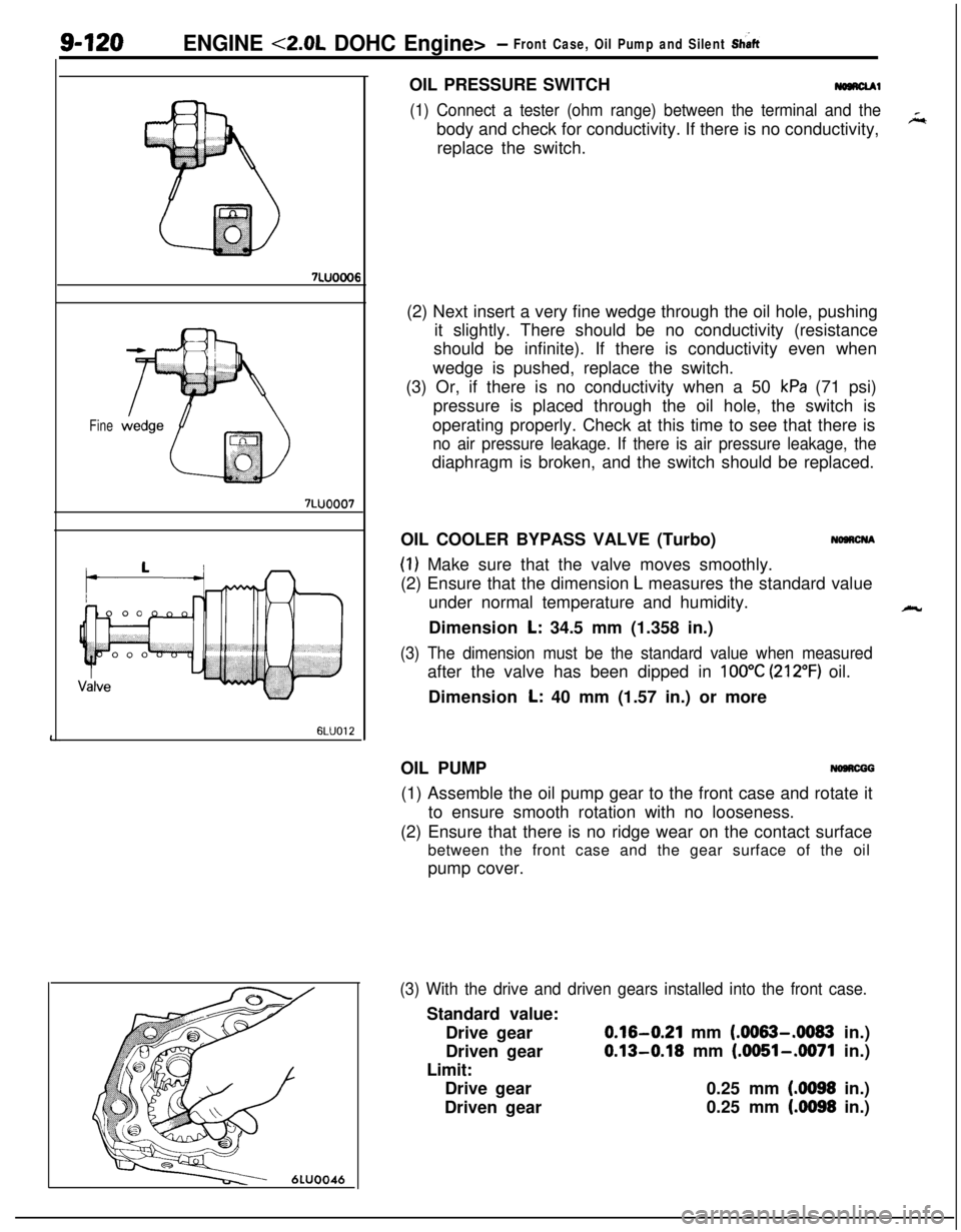
7LUOOO76LUO12OIL PRESSURE SWITCH
-1
(1) Connect a tester (ohm range) between the terminal and thebody and check for conductivity. If there is no conductivity,
replace the switch.
(2) Next insert a very fine wedge through the oil hole, pushing
it slightly. There should be no conductivity (resistance
should be infinite). If there is conductivity even when
wedge is pushed, replace the switch.
(3) Or, if there is no conductivity when a 50
kPa (71 psi)
pressure is placed through the oil hole, the switch is
operating properly. Check at this time to see that there is
no air pressure leakage. If there is air pressure leakage, thediaphragm is broken, and the switch should be replaced.
OIL COOLER BYPASS VALVE (Turbo)
NaacNA
(1) Make sure that the valve moves smoothly.
(2) Ensure that the dimension
L measures the standard value
under normal temperature and humidity.
Dimension
L: 34.5 mm (1.358 in.)
(3) The dimension must be the standard value when measuredafter the valve has been dipped in
100°C (212°F) oil.
Dimension
L: 40 mm (1.57 in.) or more
OIL PUMP
NOBRCGG(1) Assemble the oil pump gear to the front case and rotate it
to ensure smooth rotation with no looseness.
(2) Ensure that there is no ridge wear on the contact surface
between the front case and the gear surface of the oil
pump cover.
(3) With the drive and driven gears installed into the front case.Standard value:
Drive gear
0.16-0.21 mm (.0063-.0083 in.)
Driven gear
0.13-0.18 mm (.0051-.0071 in.)
Limit:
Drive gear0.25 mm
(.0098 in.)
Driven gear0.25 mm
(4098 in.)
k
Page 405 of 1216
ENGINE <2.0L DOHC Engine>- Front Case, Oil Pump and Silent Shaft9-121
II6LUOO13~DEN662
Engine oil
bOil jet
Check valve assembly
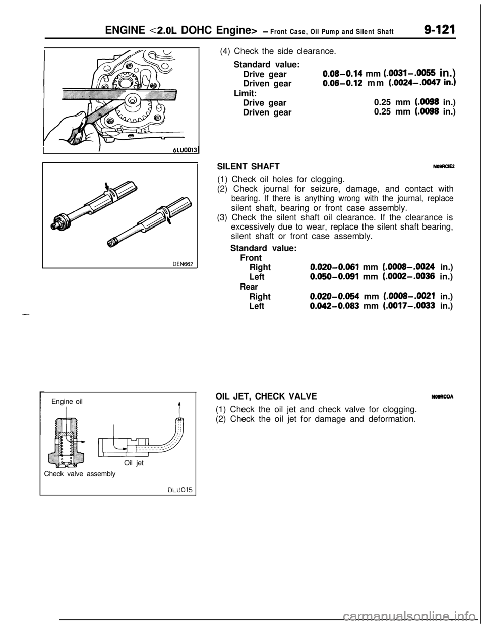
DLU015(4) Check the side clearance.
Standard value:
Drive gear
0.08-0.14 mm (.0031-.0055 in.)
Driven gear
0.06-0.12 mm (.0024-.0047 in.)Limit:
Drive gear0.25 mm
(.0098 in.)
Driven gear0.25 mm
(.0098 in.)
SILENT SHAFT
NOBRUE(1) Check oil holes for clogging.
(2) Check journal for seizure, damage, and contact with
bearing. If there is anything wrong with the journal, replacesilent shaft, bearing or front case assembly.
(3) Check the silent shaft oil clearance. If the clearance is
excessively due to wear, replace the silent shaft bearing,
silent shaft or front case assembly.
Standard value:
Front
Right
0.020-0.061 mm (.0008-.0024 in.)
Left0.050-0.091 mm (.0002-.0036 in.)
RearRight
0.020-0.054 mm (.0008-.0021 in.)
Left0.042-0.083 mm (.0017-.0033 in.)
OIL JET, CHECK VALVE
NOSRCOA(1) Check the oil jet and check valve for clogging.
(2) Check the oil jet for damage and deformation.