Page 268 of 1216

7-20COOLING - Water Pump <1.8L Engine>
aWater pump*<
l-----r,//
O-ringWater
pipe
04ROO24Identification
mark04lJoo25Alternater
brace
404uoo22
J
SERVICE POINTS OF INSTALLATIONN07ME40a
26. INSTALLATION OF O-RINGsInsert the O-ring to the water inlet pipe, and coat the,buter
circumference of the O-ring with water.,
By coating with water, the insertion to the water pump will
become easier.
Caution
1.Care must be taken not to permit engine oil or other
greases to adhere to the O-ring.
2.When inserting the pipe, check to be sure,that there
is no sand, dirt, etc. on its inner surface.
24. INSTALLATION OF WATER PUMP,
(1) Clean both gasket surfaces of water pump body and
cylinder block.
(2) Install new water pump gasket and water pump
assembly and tighten the bolts.
Bolt diameter (d)Torque
x length (e) mm (in.)Nm (ftlbs.)I
I I148 x 28 (.31 x 1.1)112-15 (9-10) 1
I I2
71 8 x 70 (.31 x 2.76) 120-27 (15-19)(
348x55(.31x2.17)12-15(9-10)
448x28(.31x1.1)I
22. INSTALLATION OF TIMING BELT B/20. FLANGE-For information concerning the installation of the timing
belt
B and the flange, refer to GROUP g-Timing Belt B.
18. INSTALLATION OF TIMING BELT/l7. TIMING BELT
FRONT LOWER COVER/lG. TIMING BELT FRONT UP-
PERCOVER/ 15. SEMI-CIRCULARPACKING / 13.
ROCKER COVERFor information concerning the installation of the timing
belt, the timing belt front lower cover, the timing belt front
upper cover, the semi-circular packing, and the rocker
cover, refer to GROUP
g-Timing Belt.
5. DRIVE BELT TENSION ADJUSTMENT
Refer to
P.7-9.
4. DRIVE BELT TENSION ADJUSTMENT
Refer to GROUP
19-Service Adjustment Procedures.
3. DRIVEBELTTENSIONADJUSTMENT
Refer to GROUP
24-Service Adjustment Procedures,
Page 269 of 1216

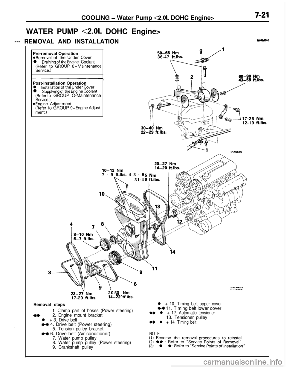
COOLING - Water Pump <2.0L DOHC Engine>7-21WATER PUMP <2.0L DOHC Engine>
--- REMOVAL AND INSTALLATION
No7Ms-B
_Pre-removal Operation
@Removal of the Under Coverl Draining of the Engine Coolant(Refer to GROUP O-MaintenanceService.)
50-65 Nm136-47 ft.lbs.
60-60 Nm
Post-installation Operation
l installation of the Under Coverl supplying of the Engine Coolant(Refer to GROUP O-MaintenanceService.)*Engine Adjustment
(Ri+&; to GROUP g-Engine Adjust-
lo-12 Nm
7-9 ft.lbs. 43-5
31-4
III-40 Nm!-29 ft.lbs.17-26
12-19OlAO560
20-27 Nm14-20 ft.lbs.
23-27 Nm
17-20 ft.lbs.
”20-’ 30 Nm” .““*wY--
-~ . .14-22 ft.ll3s.Removal steps
I. Clamp part of hoses (Power steering)
+*2. Engine mount bracket
l + 3. Drive belte+ 4. Drive belt (Power steering)5. Tension pulley bracket
I)4 6. Drive belt (Air conditioner)7. Water pump pulley
8. Water pump pulley (Power steering)
9. Crankshaft pulley
l + 10. Timing belt upper coverI)4 11. Timing belt lower cover+I) l + 12. Automatic tensioner13. Tensioner pulley
+I) l + 14. Timing belt
NOTE(1) Reverse the removal procedures to reinstall.(2) +e : Refer to “Service Points of Removal”.(3) l 4 : Refer to “Service Points of Installation”
,“k.
Page 272 of 1216

7-24COOLING - Water Pump <2.0L DOHC Engine>
Identification mark
4lternater brace
6COOOlO
20. INSTALLATION OF WATER PUMP
(1) Clean both gasket surfaces of water pump body and
jir,cylinder block.
(2) Install new water pump gasket and water pump ’
assembly and tighten the bolts.
No, IdentificationBolt diameter (d)Torquemarkx length (I?) mm (in.)Nm (ft.lbs.1
148x14(.31x.55)
248x22(.31x.87)12-15(g-10)
348x30(.31x1.18)
4
78x65(.31x2.56)20-27(15-191
548x28(.31x1.10)12-15(g-10)
18. INSTALLATION OF TIMING BELT B/16. FLANGEFor information concerning the installation of the timing
belt
B and the flange, refer to GROUP g-Timing Belt B.
14. INSTALLATION OF TIMING BELT/lZ. AUTOMATIC 6TENSlONNER/
11. TIMING BELT LOWER COVER/ -
10. TIMING BELT UPPER COVERFor information concerning installation of the timing belt,
the automatic tensioner, the timing belt lower cover, and
the timing belt upper cover, refer to GROUP g-Timing Belt.
6. DRIVEBELT TENSIONADJUSTMENT
Refer to GROUP
24-Service Adjustment Procedures.
4. DRIVE BELT TENSION ADJUSTMENT
Refer to GROUP 1
g-Service Adjustment Procedures.
3. DRIVE BELT TENSION ADJUSTMENT
Refer to
P.7-9.
Page 279 of 1216

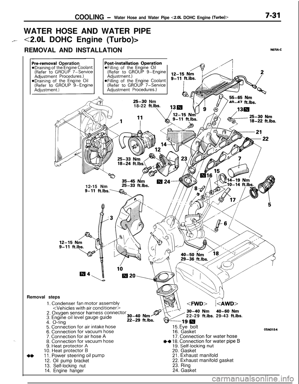
COOLING -Water Hose and Water Pipe <2.0L DOHC Engine (Turbo)>7-31WATER HOSE AND WATER PIPE
7--<2.0L DOHC Engine (Turbo)>
REMOVAL AND INSTALLATION
N071A-C
. .
ation OperationPost-installi@Filling of the Engine Oil(Refer to GROUP g-EngineaFilling of the
Engine Coolant(Refer to GROUP 7-ServiceAdjustment Procedures.)
Pre-removal OperationeDraining of the Engine Coolant(Refer to GROUP 7-ServiceAdjustment Procedures.)*Draining of the Engine Oil(Refer to GROUP g-Engine
25-30 Nm
18-22 ftlbs.4n-47 ft.lbs.
w35-45 N/m12-15 Nm25-33 ft.lbs.
9- 11ft.lbs.----Q&Removal steps
1. Condenser fan motor assembly2. Oxygen sensor harness connector3. Engine oil level gauge guide4. O-ring5. Connection for air intake hose6. Connection for vacuum hose7. Connection for air hose A8. Connection for vacuum hose9. Heat protector A10. Heat protector B
4*11. Power steering oil pump
12. Oil pump bracket
13. Self-locking nut
14. Engine hanger22-29
ft.lbs. 29-43 ft.lbs.
15. Eye bolt16. Gasket17. Connection for water hose
I)+ 18. Connection for water pipe B19. Self-locking nut20. Gasket21. Exhaust manifold22. Exhaust manifold gasket
23. Ring
24. Gasket
05m154
Page 281 of 1216

COOLING- Water Hose and Water Pipe <2.0L DOHC Engine (Turbo)>7-330140552
Mating marks
04A0090
rMating marks
04A0090
SERVICE POINTS OF REMOVALNO7lBAC311. DISCONNECTION OF POWER STEERING OIL PUMP
Disconnect the oil pump with hoses from the bracket.
NOTEThe removed power steering oil pump should be fastened
(by using rope, etc.) in a position that will not interfere with
the removal/installation of the engine assembly.
27. REMOVAL OF TURBOCHARGER ASSEMBLY
Remove the turbocharger assembly with the exhaust
fitting, water pipe A, water pipe
B and the oil pipe attached
to it.
38. DISCONNECTION OF RADIATOR LOWER HOSE
After making mating marks on the radiator hose and the
hose clamp, disconnect the radiator hose.
INSPECTIONN07lCAAa3WATER PIPE AND HOSE INSPECTION
Check the water pipe and hose for cracks, damage, clog and
replace them if necessary.
SERVICE POINTS OF INSTALLATION
N071DAJ345. INSTALLATION OF
0-RING/44. WATER INLET PIPE
Insert the O-ring to the water inlet pipe, and coat the outer
circumference of the O-ring with water.
By coating with water, the insertion to the water pump will
become easier.
Caution
Care must be taken not to permit engine oil or other
greases to adhere to the O-ring.
38. CONNECTION OF RADIATOR LOWER HOSE
Align the mating marks on the radiator hose and hose
clamp and then connect them; then, applying force in the
direction indicated by the arrow in the illustration, seat the
clamp to the trace marks of the previous connection.
Caution
Be sure to install the hose clamps at the trace marks ofthe previous connection.
Page 297 of 1216

ENGINE - SDecificationsItems
TensionN (Ibs.)
Inspection
New belt
Used belt
For power steering pump
Deflectionmm (in.)
Inspection
Timing belt tensionmm (in.)Standard Value
250-500 (55-l 10)
470-570 (104- 126)
320-400 (71-88)
6.0-9.0 (.236-.354)14
(.55)NOTE
O.D.: Outer Diameter
I.D.: Inner Diameter
OS.: Oversize Diameter
U.S.: Undersize Diameter<2.0L DOHC Engine>
-ItemsStandard ValueLimit
Engine adjustments
Engine compression pressurekPa (psi)
(Turbo)
Engine compression pressure difference
between each cylinderkPa (psi)
Intake manifold vacuum at idlemm Hg
(in.Hg)
Timing belt “B” tensionmm (in.)
-
-
-490 (19.3)
480 (18.9)
5-7
(.20-.28)Cylinder head
Overall heightmm (in.)132.0 (5.197)
Flatness of gasket surfacemm (in.)
Flatness of manifold mounting surfacemm (in.)
Oversize rework dimension of valve seat hole
mm (in.)
Intake0.3
(.012) 0,s.0.6 (0.24)
0,s.Exhaust 0.3
(.012) OS.
0.6
(.024) 0.S~ less than 0.05
(.0020)Less than 0.15
(.0059)
35.300-35.325(1.3898-1.3907)
35.600-35.625
(1.4016-l .4026)
33.300-33.325(1.3110-1.3120)
33.600-33.625
(1.3228- 1.3238)Limit
Min. 960 (137)
Min. 800 (114)
Max. 100 (14)
-0.2
(-,008)”*Limit must be -0.2
(- .008) combined
with amount of
grinding of cylinder
block gasket surface.
0.2
(.008)0.3
(.012)
Page 301 of 1216
ENGINE - Specifications
..--Items
Drive belt
For alternator
Deflectionmm (in.)
Inspection
New belt
Used belt
Tension
N (Ibs.)
Inspection
New belt
Used belt
For air conditioner compressor
Deflectionmm (in.)
Inspection
New belt
Used belt
Tension
N (Ibs.)
Inspection
New belt
Used belt
For power steering pump
Deflectionmm (in.)
Inspection
Timing belt
Amount;; I;;;j;ction of auto tensioner
rodTiming belt “B” tensionmm (in.)
Amount;: I;;;jytion of auto tensioner
rod(distance between the tensioner arm and
auto tensioner body)
Auto tensioner rod retraction
wmNOTE
O.D.: Outer Diameter
I.D.: Inner Diameter
0,s.: Oversize Diameter
U.S.: Undersize DiameterStandard Value
9.0- 11.5 (.354-.453)
7.5-9.0 (.295-.354)10
i.394)
250-500 (55-l 10)
500-700 (11 o-1 54)400 (88)
Approx. 8
(.315)
5.0-5.5 (.197-.217)
6.0-7.0 (.236-,276)
250-500 (55- 110)
470-570 (104-126)
320-400 (71-88)
6.0-9.0 (.236-,354)12
(.47)5-7
(.20-.28)3.8-4.5
(.15-,1812.5-3Limit
Page 302 of 1216

9-18ENGINE - Specifications
TORQUE SPECIFICATIONS
NO9CG-Items
Engine mount insulator nut (large)
(small)
Engine mount bracket nut or bolt
Transaxle mount insulator nut
Transaxle mount to body
Front roll stopper insulator nut
Front roll stopper bracket to centermember
Rear roll stopper insulator nut
Rear roll stopper bracket to centermember
Accelerator cable adjusting bolts
Fuel high pressure hose to delivery pipe
Ground cable to air intake manifold
Control wiring harness to air intake plenum
Power steering oil pump to bracket
Air conditioner to bracketcompressor
Exhaust pipe clamp bolt
Exhaust pipe to rubber hanger
Oil drain plug
panOil (bolts)
pan(nuts)VVater pulley
pump
Tensioner pulley bracket (air conditioner compressor)
Timing belt front coverCrankshaft sprocket
Camshaft sprocket
Timing belt “B” tensioner bolt
-eft engine support bracket3il switch
pressure3il unit
pressure gauge
Iii filter bracket
Iii cover
pumpqelief plug
‘lywheel or drive plate
ixhaust pipe bracket
support
‘rant roll stopper bracket
Iear roll stopper bracket‘rant engine bracket
support
:1.8L Engine>
Oil screen
Rocker cover
Camshaft bearing cap bolt (6 x 20)
(8 x 65)
Exhaust pipe to exhaust manifold
Intake manifold bolt
stay
Cylinder head bolt
Crankshaft pulley
Crankshaft damper pulleyNm
ftlbs.
60-8043-58
30-4022-29
50-6536-47
60-8043-58
40-5029-36
50-6536-47
40-5029-36
40-5029-36
40-5029-36
4-63-4
4-6
3-4
4-6
3-4
4-6
3-4
35-45
25-33
23-27
17-20
30-4022-29
10-157-l 135-45
25-33
6-84-6
5-73.5-5
8-106-7
23-27
17-20
10-127-9
110-13080-94
80-10058-72
15-2211-16
30-4222-308-126-9
8-126-9
15-2211-16
15-1811-13
40-5029-36
130-14094-101
30-4222-3055-75
40-54
110-13080-94
50-7036-51
18-2513-18
5-74-5
20-2714-2019-21
14-15
30-4022-29
18-2513-18
70-7551-5415-1811-13
15-1811-13