Page 367 of 1216

r-.ENGINE <2.0L DOHC Engine>
- Engine AssemblyS-83
OlA0177
-mpp.-/- --OlA0553
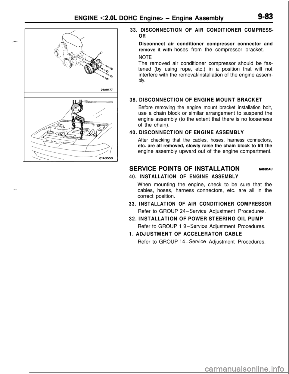
33. DISCONNECTION OF AIR CONDITIONER COMPRESS-
ORDisconnect air conditioner compressor connector and
remove it with hoses from the compressor bracket.
NOTEThe removed air conditioner compressor should be fas-
tened (by using rope, etc.) in a position that will not
interfere with the removal/installation of the engine assem-
bly.
38. DISCONNECTION OF ENGINE MOUNT BRACKET
Before removing the engine mount bracket installation bolt,use a chain block or similar arrangement to suspend the
engine assembly (to the extent that there is no looseness
of the chain).
40. DISCONNECTION OF ENGINE ASSEMBLY
After checking that the cables, hoses, harness connectors,etc. are all removed, slowly raise the chain block to lift the
engine assembly upward out of the engine compartment.
SERVICE POINTS OF INSTALLATION
NOSSDAU
40. INSTALLATION OF ENGINE ASSEMBLYWhen mounting the engine, check to be sure that the
cables, hoses, harness connectors, etc. are all in the
correct position.
33. INSTALLATION OF AIR CONDITIONER COMPRESSORRefer to GROUP
24-Service Adjustment Procedures.
32. INSTALLATION OF POWER STEERING OIL PUMPRefer to GROUP 1
g-service Adjustment Procedures.
1. ADJUSTMENT OF ACCELERATOR CABLERefer to GROUP 14-Service Adjustment Procedures.
Page 379 of 1216

ENGINE <2.0L DOHC Engine> - Timing Belt
TIMING BELT
REMOVAL AND INSTALLATION
I
Pre-removal Operation*Removal of Under Cover
I
50-65 Nm36-47 ft.lbs.
50-65“Nm36-47 ft:lbs.30-60-80
Nm22-20-3\0
Nm14-22 ftlbs.
lo-i2 Nm7-9 ftlbs.
Removal steps
1. Clamp for pressure hose (power steering)2. Bracket
3. Engine mount bracket
4. Clamp of return pipe (power steering)
5. Drive belt (alternator)6. Drive belt (power steering)
7. Tensioner pulley bracket
8. Drive belt (air conditioner)9. Water pump pulley
10. Water pump pulley (power steering)11. Crankshaft pulley12. Timing belt front upper cover13. Timing belt front lower cover
14. Center cover
15. Breather hose16. PCV hose
17. Connection for spark plug cables
l *
4*
NOTE4+ : Refer to “Service Points of Installation”.
WA0581
18.Rocker cover19.Semi-circular packing
20.Plug rubber2 1.Auto tensioner
22.Timing belt
23.Tensioner pulley
24.Tensioner arm
25.Idle oullev26. Camshaft sprocket
27. Oil pump sprocket
28. Crankshaft sprocket bolt
29. Special wastier
30. Crankshaft sprocket
31. Flange32. Tensioner
“B”33. Timing belt “B”
34. Silent shaft sprocket
35. Spacer36. Crankshaft sprocket “B”
37. Left engine support bracket
38. Timing belt rear right cover
39. Timing belt rear left cover (upper)
40. Timing belt rear left cover (lower)
Page 380 of 1216

9-96ENGINE <2.0L DOHC Engine> - Timing Belt
116
/18
Iv- IL 1’11117-9 ftlbs.
\43-49
Nm-_---. . .
30-42 Nm$0
22-30 ftlbs.
\
j2 \ 36
33
15-22 Nm
11-16 ftlbs.
I20-27 Nm\h \
14-20 f&.lbs.110-130 Nm cI,60-94 f
\z/OIAOS83-ama .I~..su--Du Nrnt Ibs .,iJ 36-43 ft.lbs.. .
Installation steps
40. Timing belt rear left cover (lower)
39. Timing belt rear left cover (upper)
38. Timing belt rear right cover37. Left engine support bracket
I)+ 36. Crankshaft sprocket “B”
l + 35. Spacer34. Silent shaft sprocket
l + 33. Timing belt “B”
l 4Adjustment of timing belt “B” tension
32. Tensioner “B”
l + 31. Flange++ 30. Crankshaft sprocket
29. Special washer
28. Crankshaft sprocket bolt
l + 27. Oil pump sprocketl + 26. Camshaft sprocket25. Idle pulley
e+ 21. Auto tensioner24. Tensioner arml 23. Tensioner pulleyl + 22. Timing belt
l 4Adjustment of timing belt tension20. Plug rubberl + 19. Semi-circular packingl 4 18. Rocker cover
17. Connection for spark plug cables16. PCV hose15. Breather hose14. Center cover
l + 13. Timing belt front lower covere+ 12. Timing belt front upper cover11. Crankshaft pulley10. Water pump pulley (power steering)
9. Water pump pulley
l +8. Drive belt (air conditioner)7. Tensioner pulley bracketI)+ 6. Drive belt (power steering)l +5. Drive belt (alternator)
4. Return pipe clamp bolt (power steering)3. Engine mount bracket
2. Bracket
1. Clamp for pressure hose (power steering)
NOTE+4 : Refer to “Service Points of Installation”.
Page 392 of 1216
9-l 08ENGINE <2.0L DOHC Engine> - Timing Belt
.hread diameter
\: 6 x 16(24 x .63)OlAOO45I: 6 x 18 (.24x .70)‘. 6 x 25 (.24 x .98);. 6x28 (.24~1.10) mm (in,)13. INSTALLATION OF TIMING BELT LOWER COVER/
12. TIMING BELT UPPER COVER
F-sThe dimensions of the installation bolts for the timing
covers differ according to the installation location, so be
sure not to install the bolts in the incorrect locations.
8. TENSION ADJUSTMENT OF THE AIR CONDITIONER
COMPRESSOR DRIVE BELT
Refer to GROUP
24-Service Adjustment Procedures.
6. DEFLECTION ADJUSTMENT OF POWER
STEERING OIL .++PUMP DRIVE BELT
Refer to GROUP 1
g-Service Adjustment Procedures.
5.TENSION ADJUSTMENT OF THE ALTERNATOR DRIVE
BELTRefer to GROUP
7-Maintenance Service.
Page 442 of 1216

II-20INTAKE AND EXHAUST - Turbocharger
TURBOCHARGER
REMOVAL AND INSTALLATION
II
NHLA-
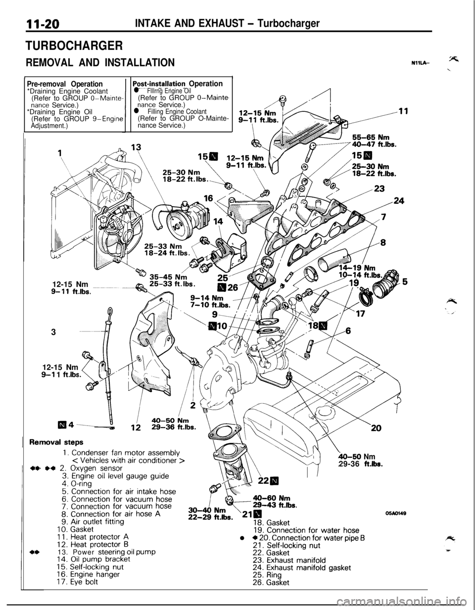
Pre-removal Operation*Draining Engine Coolant
(Refer to GROUP
0-Maintenance Service.)
*Draining Engine Oil
(Refer to GROUP g-Engine
Adjustment.)1
Po+installation Operationl Flllrng Engine Oil(Refer to GROUP O-Main@
nance Service.)l Filling Engine Coolant(Refer to GROUP O-Mainte-
nance Service.)
12-15 Nm12-15 Nm
9- 11ft.lbs.3
12-15 Nm
9-l 1 ftlbs
moval steps
1. Condenser fan motor assembly< Vehicles with air conditioner >) *4 2. Oxygen sensor3. Engine oil level gauge guide4. O-ring
5. Connection for air intake hose6. Connection for vacuum hose7. Connection for vacuum hose8. Connection for air hose A9. Air outlet fitting
10.Gasket1 1.Heat protector A12. Heat protector B13. Power steering oil pump14. Oil pump bracket15.Self-locking nut16.Engine hanger17.Eye bolt
h-50 Nm29-36 ft.lbs.
19. Connection for water hosel * 20. Connection for water pipe f321. Self-locking nut22. Gasket23. Exhaust manifold24. Exhaust manifold gasket25. Ring26. Gasket
05M1149
Page 444 of 1216

INTeKE AND EXHAUST - Turbocharger
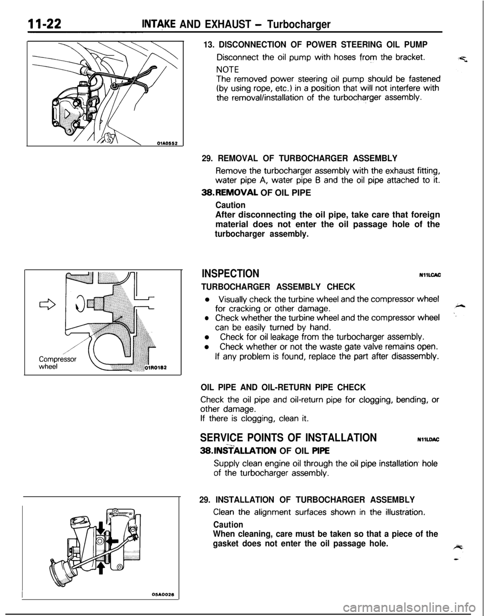
13. DISCONNECTION OF POWER STEERING OIL PUMP
Disconnect the oil pump with hoses from the bracket.
NOTE
The removed power steering oil pump should be fastened
(by using rope, etc.) in a position that will not interfere with
the removal/installation of the turbocharger assembly.
I05AOO26
29. REMOVAL OF TURBOCHARGER ASSEMBLY
Remove the turbocharger assembly with the exhaust fitting,water
pipe A, water pipe 6 and the oil pipe attached to it.3B.REMOVAL OF OIL PIPE
CautionAfter disconnecting the oil pipe, take care that foreign
material does not enter the oil passage hole of the
turbocharger assembly.
INSPECTIONNllLCAC
TURBOCHARGER ASSEMBLY CHECKl
Visually check the turbine wheel and the compressor wheelfor
cracking or other damage.
lCheck whether the turbine wheel and the compressor wheel
can be easily turned by hand.l
Check for oil leakage from the turbocharger assembly.l
Check whether or not the waste gate valve remains open.
If any problem is found, replace the part after disassembly.
OIL PIPE AND OIL-RETURN PIPE CHECK
Check the oil pipe and oil-return pipe for clogging, bending, or
other damage.
If there is clogging, clean it.
SERVICE POINTS OF INSTALLATIONNllLDAC-x_3SlNSTALLATlON OF OIL PlPE
Supply clean engine oil through the oil pipe installation hole
of the turbocharger assembly.
29. INSTALLATION OF TURBOCHARGER ASSEMBLY
Clean the alignment surfaces shown in the illustration.
Caution
When cleaning, care must be taken so that a piece of the
gasket does not enter the oil passage hole.
Page 450 of 1216

11-28INTAKE AND EXHAUST - Exhaust Manifold ~2.0~ DOHC Enoine (Turbo)>
EXHAUST MANIFOLD <2.0L DOHC Engine (Turbo)>
REMOVAL AND INSTALLATION
Pre-removal Operation*Draining Engine Coolant(Refer to GROUP O-Mainte-nance Service.)*Draining Engine Oil(Refer to GROUP O-Mainte-nance Service.)
Rennova1 steps
1.Condenser fan motor assemblyOxygen sensor connectorEngine oil level gauge guideO-ring
\30-40 Nm22-29 ft.lty3. & (
EJ\\=a-50 N
4 .ri29-38 ftk.
,
Post-installation Operation@Filling Engine Oil(Refer to GROUP O-Mainte-nance Service.)@Filling Engine Coolant(Refer to GROUP O-Mainte-nance Service.)NllNA-C
130 25-30 Nmd/18-22 ft.lbs.
;:4.
s5:7.
::10.Ii.12.13.14.15.
Connection for air intake hose
Connection for vacuum hoseConnection for vacuum hoseConnection for air hose AHeat protector AHeat protector 6Power steering oil pumpOil pump bracketSelf-locking nut
Engine hangerEve bolt
16. Gasket17. Connection for water hose
19IBWI 18. Connection for water pipe B19. Self-locking nut20.
Gasket
05Ao15421.
Exhaust manifold22. Exhaust manifold gasket23.
Ring24. Gasket
NOTE(1) Reverse the removal procedures to reinstall.(2) +, : Refer to “Service Points of Removal”.(3) l * : Refer to “Service Points of Installation”(4) m : Non-reusable parts
Page 451 of 1216
INTAKE AND EXHAUST - Exhaust Manifold II-28
OlAO552
05K55;,
SERVICE POINTS OF REMOVALNllNBAl
11. DISCONNECTION OF POWER STEERING OIL PUMP
:
Disconnect the oil pump with hoses from the bracket.
NOTE
The removed power steering oil pump should be fastened
(by using rope, etc.) in a position that will not interfere with
the removal/installation of the exhaust manifold.
lNSPECTlONNllNCALl
Check the following points; replace the part if a problem is
found.EXHAUST MANIFOLD
Check for damage or cracking of any part.EXHAUST MANIFOLD GASKET
Check for flaking or damage of the gasket.
SERVICE POINTS OF INSTALLATIONNllNQAG
18. INSTALLATION OF WATER PIPE (BI
Before installing to the water inlet pipe, apply machine oil to
the inner surface of the pipe flare.