Page 663 of 1216

-
c. .
STEERING - Service Adiustment Procedures 3:945
Shut-off valve
Pressure gauge
CHECKING THE STEERING GEAR PETENTION HYDRAULIC
PRESSURE1. Disconnect the pressure hose from the oil
pbmd, and iheh
connect the special tools.
2.Bleed the air, and then turn the steering wheel several timeswhile the vehicle is not moving so that the temperature of
the fluid rises to approximately
50~60OC (122~14pyF).
3. ‘Start the engine and idle it at 1,000 +
100 rem: .‘,’.
4.Fully close and fully open the shut-off valve of the pressure
gauge.
5.Turn the steering wheel all the way to the left or right; then
check whether or not the retention hydraulic pressure is the
standard value.
Standard value: 7.5-8.2 MPa (1,067-1,166 psi)6. When not within the standard value, overhaul the steering
gear box.
Remeasure fluid pressure.
7.Remove the special tools, and then tighten the pressure hoseto the specified torque.
8. Bleed the system.
OIL PRESSURE SWITCH CHECKNlSFUAB1. Disconnect the pressure hose from the oil pump, and then
connect the special tools.
2.Bleed the air, and then turn the steering wheel several timeswhile the vehicle is not moving so that the temperature of
the fluid rises to approximately
50-60°C (122-14OOF).3. The engine should be idling.
4. Disconnect the connector for the oil pressure switch, and
place an ohmmeter ,in position.
5.Gradually close the shut-off valve of the pressure gauge andincrease the hydraulic pressure then check whether the
hydraulic pressure that activates the switch is the standard
value.
Standard value: 1.5-2.0 MPa (213-284 psi)
6. Gradually open the shut-off valve and reduce the hydraulic
pressure; then check whether the hydraulic pressure that
deactivates the switch is the standard value.
Standard value: 0.7-1.2 MPa (100-171 psi)
7.Remove the special tools, and then tighten the pressure hoseto the specified torque.
8. Bleed the system.
Page 676 of 1216

19-28STEERING - Power Steering Gear Box
POWER STEERING GEAR BOXREMOVAL AND INSTALLATION
-
NlSPA--
Pre-removal Operation@Draining of the Power Steering Fluid@Removal of Transfer:1&&r:, GROUP 21 -Transfer.)50-65 Nm36-47 ft.lbs.
I/a
Post-installation Operationl Installation of Transfer(:zD:” GROUP 21 -Transfer.)
l SSy,lying of the Power Steeringl Bleedino of the Power Steering
Fluid
Liie(Refer to P.19-13.1l khecking of Steering Wheel Posi-tion with Wheels Straight Ahead*Adjustment of the Front Wheel
Alignment
(Refer to GROUP Z-Service Ad-
justment Procedures.)
Removal steps1.
“,;;rt assembly and gear box connecting
bolt
2. Connection for return tube
3. Connection for pressure hose
4. Cotter pin
5.
Aft-cd end and knuckle connecting
4I)f3: H,“a:od end
8. Stabilizer bar bracket
9. Front roll stopper mounting bolt10. Center member rear mounting bolt
4411. Front exhaust pipe l * l + 12. Gear box assembly
l + 13. Mounting rubber
(I) Reverse the removal procedures to reinstall.(2) +e : Refer to “Service Points of Removal”.(3) .* : Refer to “Service Points of Installation”.(4) q : Non-reusable parts(4) lli
3oh2 Nm22-30 ftlba.^a-aa I.au-IUU NrnI
IO-15 Nm22-29
ft.lbs.
15-20 Nm15-20 Nm
11-14 ft.lbs.
13A027612-18 Nm
A-34 IUm
K-
1 j-+ft.lbs.
:II I-.5
/ .2!
i!!1
NOTEW-W Nm43-58
ft.lbs.13A0353
Page 677 of 1216

STEERING - Power Steering Gear Box
lS1017S
I /Mounting rubber
IIMdting clamp13Roo77
5SERVICE POINTS OF REMOVAL
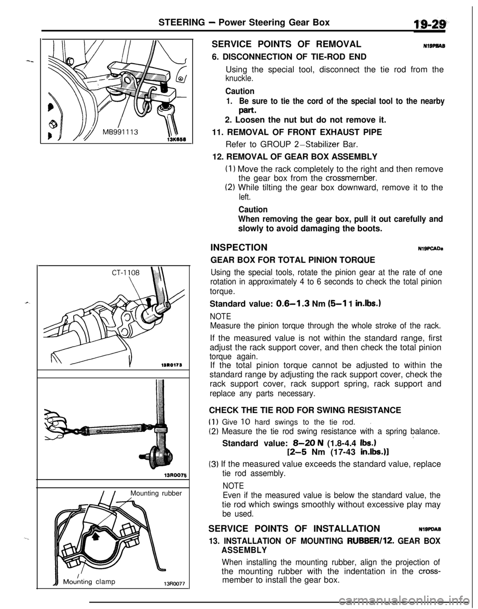
NIBPNAB6. DISCONNECTION OF TIE-ROD END
Using the special tool, disconnect the tie rod from the
knuckle.
Caution
1.Be sure to tie the cord of the special tool to the nearby
part.2. Loosen the nut but do not remove it.
11. REMOVAL OF FRONT EXHAUST PIPE
Refer to GROUP
2-Stabilizer Bar.
12. REMOVAL OF GEAR BOX ASSEMBLY
(I 1 Move the rack completely to the right and then remove
the gear box from the
crossmember.
(2) While tilting the gear box downward, remove it to the
left.
Caution
When removing the gear box, pull it out carefully andslowly to avoid damaging the boots.
INSPECTION
NlSPCADaGEAR BOX FOR TOTAL PINION TORQUE
Using the special tools, rotate the pinion gear at the rate of one
rotation in approximately 4 to 6 seconds to check the total pinion
torque.Standard value:
0.6-l .3 Nm (5-l 1 in.lbs.1
NOTE
Measure the pinion torque through the whole stroke of the rack.If the measured value is not within the standard range, first
adjust the rack support cover, and then check the total pinion
torque again.If the total pinion torque cannot be adjusted to within the
standard range by adjusting the rack support cover, check the
rack support cover, rack support spring, rack support and
replace any parts necessary.CHECK THE TIE ROD FOR SWING RESISTANCE
(1) Give 10 hard swings to the tie rod.I
(2) Measure the tie rod swing resistance with a spring balance.
’Standard value: 8-20 N (1.8-4.4 Ibs.)
12-5 Nm (17-43 in.lbs.)l
(3) If the measured value exceeds the standard value, replace
tie rod assembly.
NOTE
Even if the measured value is below the standard value, thetie rod which swings smoothly without excessive play may
be used.SERVICE POINTS OF INSTALLATION
Nl9PDA9
13. INSTALLATION OF MOUNTING RUBBER/lZ. GEAR BOX
ASSEMBLY
When installing the mounting rubber, align the projection ofthe mounting rubber with the indentation in the
cross-member to install the gear box.
Page 678 of 1216

19-30STEERING - Power Steering Gear Box
DISASSEMBLY AND REASSEMBLY
12-18
Nm9-13 ftlbs.
17-28 Nm17 ,-12 19 ft.lbs.rSteering gear seal k!t
Grease
23;>.
50155 Nm36-40 ft.lbs.I
I2b
I‘\SO-56 Nm36-40 ft.lbs.
80-100 Nm : _58-72 ft.lbs./ /
Disassembly steps1. Tie rod end locking nut
l 42. Tie rod end+I) I)+ 3. Dust cover
4. Bellows clip
a*5. Bellows band
*a 6. Bellows4,7. Tab washer
l 48. Tie rods
9. Feed tube
10. O-rings
*aAdjustment of total pinion torque
+* l * II. End plug12. Self-locking nut
13. Locking nut
l * l * 14. Rack support cover
_- -lb. Hack SUppOrt sprlngw 16. Rack support
17. Valve housing
+* l * 18. Oil seal,+ 19. Pinion and valve assembly
l + 20. Seal ringmo25a
+e l a 21. Ball bearingl * l * 22. Oil seall * l 4 23. Circlip
24. Rack stopper
l * 25. Rack bushing
4* l * 26. Rackl * 27. O-ring
+* l + 28. Oil seal29. Seal ring
30. O-ring
++ l 31. Ball bearing+W l 32. Needle roller bearing+* l a 33. Oil seal+* l a 34. Back-up washer
35. Rack housing
NOTE(1) Reverse the disassembly procedures to reassemble.(2) +e : Refer to “Service Points of Disassembly”.(3) l + : Refer to “Service Points of Reassembly”.(4) q : Non-reusable parts
Page 679 of 1216
STEERING - Power Steering Gear Box
13PO126SERVICE POINTS OF DISASSEMBLY
NISAK3. REMOVAL OF DUST COVER.4
IRemove the dust cover from the tie rod end.
5. REMOVAL OF BELLOWS BAND
Using a screwdriver or similar tool, loosen and then removethe boot retaining band.
7. REMOVAL OF TAB WASHER
Unstake the tab washer which fixes the tie rod and rack with
a chisel.11. REMOVAL OF END PLUG
Disconnect end plug caulking and remove end plug.
14. REMOVAL OF RACK SUPPORT COVER
Using the special tool, remove the rack support cover fromthe gear box.
Page 680 of 1216
STEERING - Power Steering Gear Box
13A0284
cket
13AO285
13R0551
13R0541
18. REMOVAL OF OIL SEAL
Using a plastic hammer, gently tap the pinion to remove it.21. REMOVAL OF BALL
BEARING/22. OIL SEAL
Using a socket, remove the oil seal and the ball bearing from
the valve housing simultaneously.23. REMOVAL OF
CIRCLIP
(1) Turn the rack stopper clockwise until the end of the
circlip comes out of the slot in the rack housing.
(2) Turn the rack stopper anticlockwise to remove the circlip.26.REMOVAL OF RACK
Pull out the rack slowly.
At this time also take out the rack stopper and the rack
bushing simultaneously.28.REMOVAL OF OIL SEAL
Partially bend oil seal and remove from rack bushing.
CautionDo not damage oil seal press
ftiing surface.
Page 681 of 1216

STEERING - Power Steering Gear Box4 $143
13130549
13Ro581
Pipe
13RO218
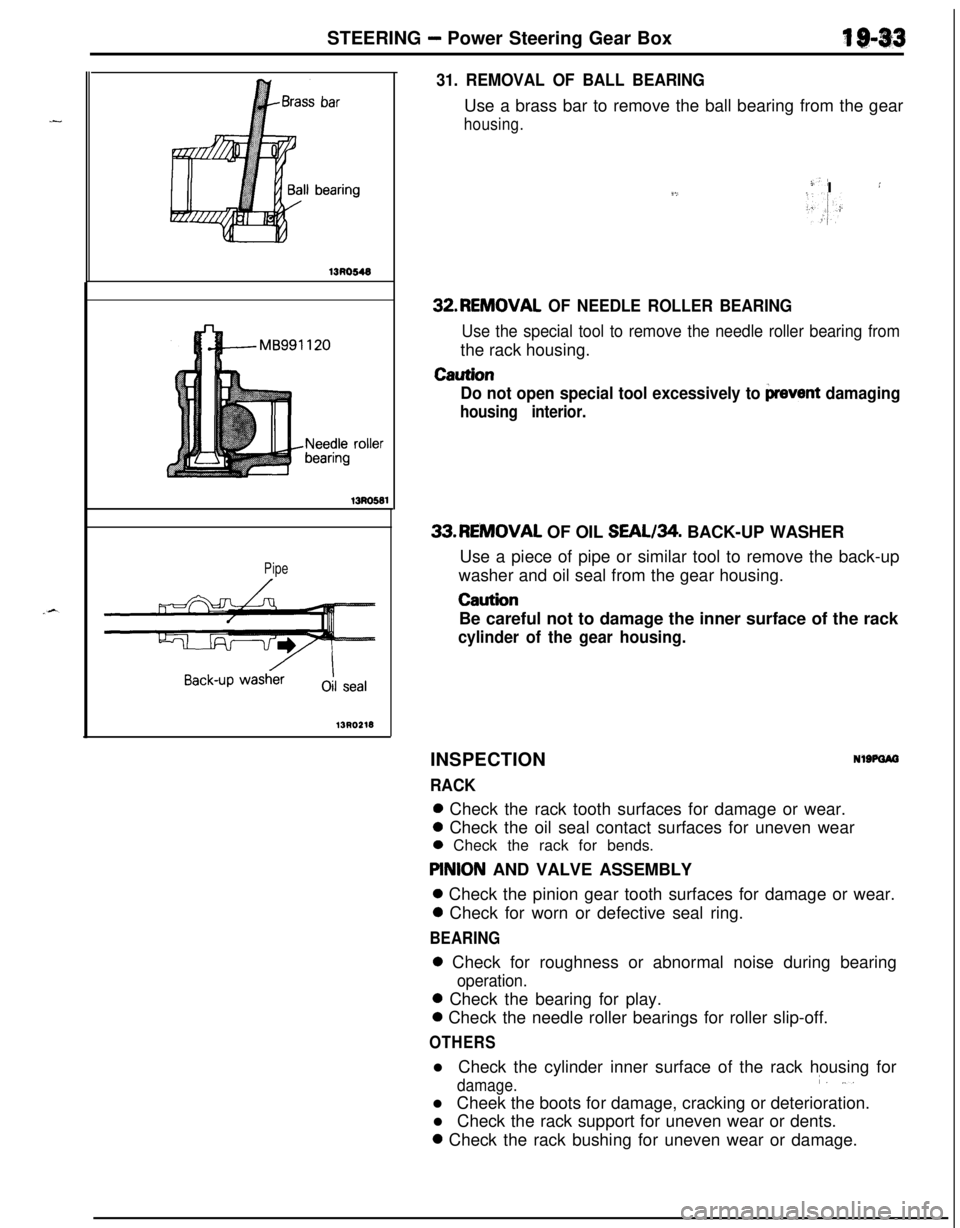
31. REMOVAL OF BALL BEARINGUse a brass bar to remove the ball bearing from the gear
housing.
-)-’9,I :
>.,I:32.REMOVAL
OF NEEDLE ROLLER BEARING
Use the special tool to remove the needle roller bearing fromthe rack housing.
Caution
Do not open special tool excessively to
prevent damaging
housing interior.33.REMOVAL OF OIL SEAL/34. BACK-UP WASHER
Use a piece of pipe or similar tool to remove the back-up
washer and oil seal from the gear housing.
CautionBe careful not to damage the inner surface of the rack
cylinder of the gear housing.INSPECTION
RACK
NlSPOIO0 Check the rack tooth surfaces for damage or wear.0 Check the oil seal contact surfaces for uneven wear
0 Check the rack for bends.
PlNlON AND VALVE ASSEMBLY0 Check the pinion gear tooth surfaces for damage or wear.0 Check for worn or defective seal ring.
BEARING0 Check for roughness or abnormal noise during bearing
operation.0 Check the bearing for play.0 Check the needle roller bearings for roller slip-off.
OTHERSl Check the cylinder inner surface of the rack housing for
damage.i. ,..l Cheek the boots for damage, cracking or deterioration.
l Check the rack support for uneven wear or dents.0 Check the rack bushing for uneven wear or damage.
Page 682 of 1216

19-34STEERING - Power Steering Gear Box
Guide
/Oil seal
Back-up washer13A0181
roller
13R0380
O-ring
13R037E
V&t hole
13K583-SERVICE POINTS OF REASSEMBLY
NlSPHAV
34. INSTALLATION OF BACK-UP WASHER133. OIL SEAL
(1) Apply a coating of the specified fluid to the outside of the
oil seal.
Specified fluid: MOPAR ATF PLUS (Automatic Trans-mission Fluid Type 7176)/Automatic
transmission fluid “DEXRON” or
“DEXRON II”
(2) Using a tool, press the back-up washer and the oil seal
into the rack housing to the specified position (where theupper surface of the press-in guide coincides with the
stepped part of the press-in tool).
32. INSTALLATION OF NEEDLE ROLLER BEARING
(1) Apply specified fluid to housing, bearing and oil seal
press fitting surface.
Specified fluid:MOPAR ATF PLUS (Automatic Trans-mission Fluid Type 7176)/Automatic
transmission fluid “DEXRON” or
“DEXRON II”
(2) Press fit needle roller bearing.
Caution
Press fit straight as valve housing is aluminium.
31. INSTALLATION OF BALL BEARING
Press fit ball bearing.28. INSTALLATION OF OIL SEAL/27. O-RING(I
1 Apply a coating of the specified fluid to the outside of the
oil seal and O-ring.
Specified fluid: MOPAR ATF PLUS (Automatic Trans-
mission Fluid Type 7176VAutomatictransmission fluid “DEXRON” or
“DEXRON II”
(2) Press fit oil seal until it touches rack bush end.
26. INSTALLATION OF RACK ASSEMBLY
(1) Apply a coating of multipurpose grease to the rack teeth
face.Grease: MOPAR Multi-mileage Lubricant PartNo.2525035 or equivalent
CautionDo not close the vent hole in the rack with grease.