Page 2170 of 4087

GENERAL MAINTENANCE
MA00M±03
There are the maintenance and inspection
items which are considered to be the owner's
responsibility. They can be performed by the
owner or be can have them done at a service
shop. These items include those which should
be checked on a daily basis, those which, in
most cases, do not require (special) tools and
those which are considered to be reasonable
for the owner to perform. Items and procedures
for general maintanance are as follows:
MA00P±04
OUTSIDE VEHICLE
1. TIRES
(a) Check the pressure with a gauge. Adjust ifnecessary.
(b) Check for cuts, damage or excessive wear.
2. WHEEL NUTS Wheel checking the tires, check the nuts for
looseness or for missing nuts. If necessary,
tighten them.
3. TIRE ROTATION It is recommended that tires be rotated every
12,000 km (7,500 miles).
4. WINDSHIELD WIPER BLADES Check for wear or cracks whenever they do not
wipe clean. Replace if necessary.
5. FLUID LEAKS
(a) Check underneath for leaking fuel, oil, water or
other fluid.
(b) If you smell gasoline fumes or notice any leak, have the cause found and corrected.
6. DOORS AND ENGINE HOOD
(a) Check that all doors including the trunk lid operate smoothly, and that all latches lock
securely.
(b) Check that the engine hood secondary latch secures the hood from opening when the
primary latch is released.
MA00R±05
INSIDE VEHICLE
7. LIGHTS
(a) C h e c k t h a t t h e h eadlights, stop lights,
tail±lights, turn signal lights, and other lights
are all working. (b) Check the headlight aiming.
8. WARNING LIGHT AND BUZZERS
Check that all warning lights and buzzers func-
tion properly.
9. HORN Check that it is working.
10. WINDSHIELD GLASS
Check for scratches, pits or abrasions.
11. WINDSHIELD WIPER AND WASHER
(a) Check operation of the wipers and washer.
(b) Check that the wipers do not streak.
12. WINDSHIELD DEFROSTER Check that the air comes out from the defroster
outlet when operating the heater air condition-
er at defroster mode.
13. REAR VIEW MIRROR
Check that it is mounted securely.
14. SUN VISORS Check that they move freely and are mounted
securely.
15. STEERING WHEEL Check that it has the specified freeplay. Be
alert for changes in steering condition, such as
hard steering, excessive freeplay or strange
noise.
16. SEATS
(a) Check that all front seat controls such as seat adjusters, seatback recliner, etc. operate
smoothly.
(b) Check that all latches lock securely in any position.
(c) Check that the locks hold securely in any latched position.
(d) Check that the head restraints move up and
down smoothly and that the locks hold securely
in ay latches position.
(e) For folding±down rear seat backs, check that the latches lock securely.
17. SEAT BELTS
(a) Ch e ck th a t th e se a t be lt syste m su ch as buckles, retractors and anchors operate
properly and smoothly.
(b) Check that the belt webbing is not cut, frayed,
worn or damaged.
18. ACCELERATOR PEDAL Check the pedal for smooth operation and un-
even pedal effort or catching.
±
MAINTENANCE (1UZ ± FE)MA±19
WhereEverybodyKnowsYourName
Page 2241 of 4087
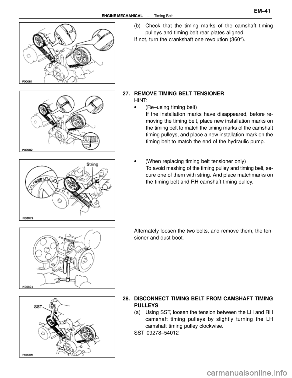
(b) Check that the timing marks of the camshaft timingpulleys and timing belt rear plates aligned.
If not, turn the crankshaft one revolution (360 5).
27. REMOVE TIMING BELT TENSIONER HINT:
w(Re±using timing belt)
If the installation marks have disappeared, before re-
moving the timing belt, place new installation marks on
the timing belt to match the timing marks of the camshaft
timing pulleys, and place a new installation mark on the
timing belt to match the end of the hydraulic pump.
w (When replacing timing belt tensioner only)
To avoid meshing of the timing pulley and timing belt, se-
cure one of them with string. And place matchmarks on
the timing belt and RH camshaft timing pulley.
Alternately loosen the two bolts, and remove them, the ten-
sioner and dust boot.
28. DISCONNECT TIMING BELT FROM CAMSHAFT TIMING PULLEYS
(a) Using SST, loosen the tension between the LH and RHcamshaft timing pulleys by slightly turning the LH
camshaft timing pulley clockwise.
SST 09278±54012
±
ENGINE MECHANICAL Timing BeltEM±41
WhereEverybodyKnowsYourName
Page 2250 of 4087
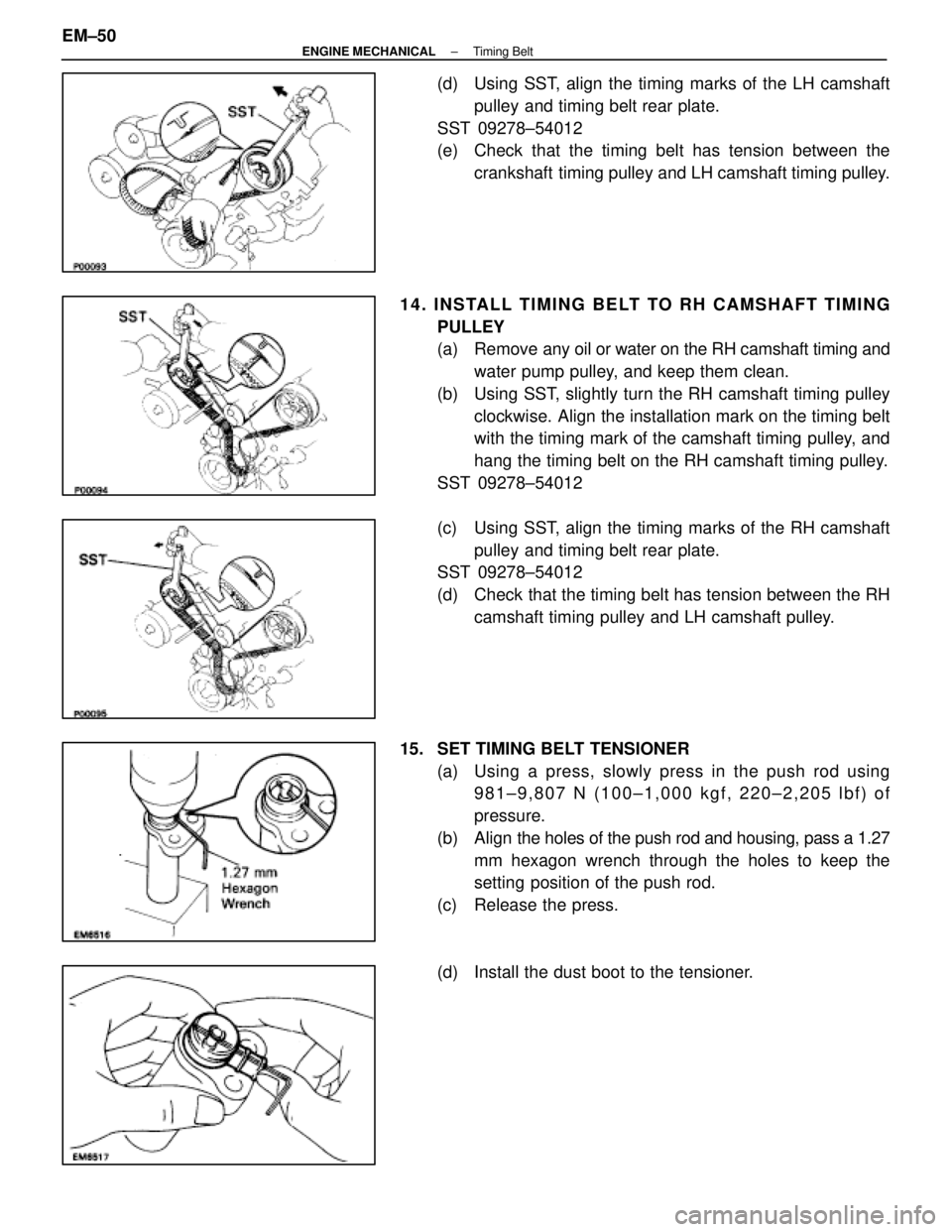
(d) Using SST, align the timing marks of the LH camshaftpulley and timing belt rear plate.
SST 09278±54012
(e) Check that the timing belt has tension between the crankshaft timing pulley and LH camshaft timing pulley.
14. INSTALL TIMING BELT TO RH CAMSHAFT TIMING PULLEY
(a) Remove any oil or water on the RH camshaft timing andwater pump pulley, and keep them clean.
(b) Using SST, slightly turn the RH camshaft timing pulley clockwise. Align the installation mark on the timing belt
with the timing mark of the camshaft timing pulley, and
hang the timing belt on the RH camshaft timing pulley.
SST 09278±54012
(c) Using SST, align the timing marks of the RH camshaft pulley and timing belt rear plate.
SST 09278±54012
(d) Check that the timing belt has tension between the RH
camshaft timing pulley and LH camshaft pulley.
15. SET TIMING BELT TENSIONER (a) Using a press, slowly press in the push rod using981±9,807 N (100±1,000 kgf, 220±2,205 lbf) of
pressure.
(b) Align the holes of the push rod and housing, pass a 1.27
mm hexagon wrench through the holes to keep the
setting position of the push rod.
(c) Release the press.
(d) Install the dust boot to the tensioner.
EM±50
±
ENGINE MECHANICAL Timing Belt
WhereEverybodyKnowsYourName
Page 2283 of 4087
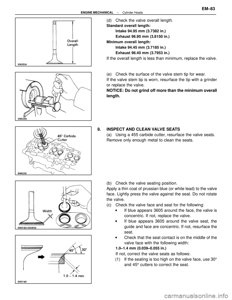
(d) Check the valve overall length.
Standard overall length:Intake 94.95 mm (3.7382 in.)
Exhaust 96.90 mm (3.8150 in.)
Minimum overall length: Intake 94.45 mm (3.7185 in.)
Exhaust 96.40 mm (3.7953 in.)
If the overall length is less than minimum, replace the valve.
(e) Check the surface of the valve stem tip for wear.
If the valve stem tip is worn, resurface the tip with a grinder
or replace the valve.
NOTICE: Do not grind off more than the minimum overall
length.
8. INSPECT AND CLEAN VALVE SEATS (a) Using a 455 carbide cutter, resurface the valve seats.
Remove only enough metal to clean the seats.
(b) Check the valve seating position.
Apply a thin coat of prussian blue (or white lead) to the valve
face. Lightly press the valve against the seat. Do not rotate
the valve.
(c) Check the valve face and seat for the following:w If blue appears 3605 around the face, the valve is
concentric. If not, replace the valve.
w If blue appears 3605 around the valve seat, the
guide and face are concentric. If not, resurface the
seat.
w Check that the seat contact is on the middle of the
valve face with the following width:
1.0±1.4 mm (0.039±0.055 in.)
If not, correct the valve seats as follows:
(1) If the seating is too high on the valve face, use 30 5
and 45 5 cutters to correct the seat.
±
ENGINE MECHANICAL Cylinder HeadsEM±83
WhereEverybodyKnowsYourName
Page 2290 of 4087
2. INSTALL VALVES(a) Using SST, push in a new oil seal.
SST 09201±41020
(b) Install the following parts:(1) Valve
(2) Spring seat
(3) Valve spring
(4) Spring retainer
(c) Using SST, compress the valve spring and place the two
keepers around the valve stem.
SST 09202±70010
(d) Using a plastic±faced hammer, lightly tap the valve stem
tip to assure proper fit.
3. INSTALL VALVE LIFTERS AND SHIMS Check the valve lifter rotates smoothly by hand.
EM±90
±
ENGINE MECHANICAL Cylinder Heads
WhereEverybodyKnowsYourName
Page 2293 of 4087
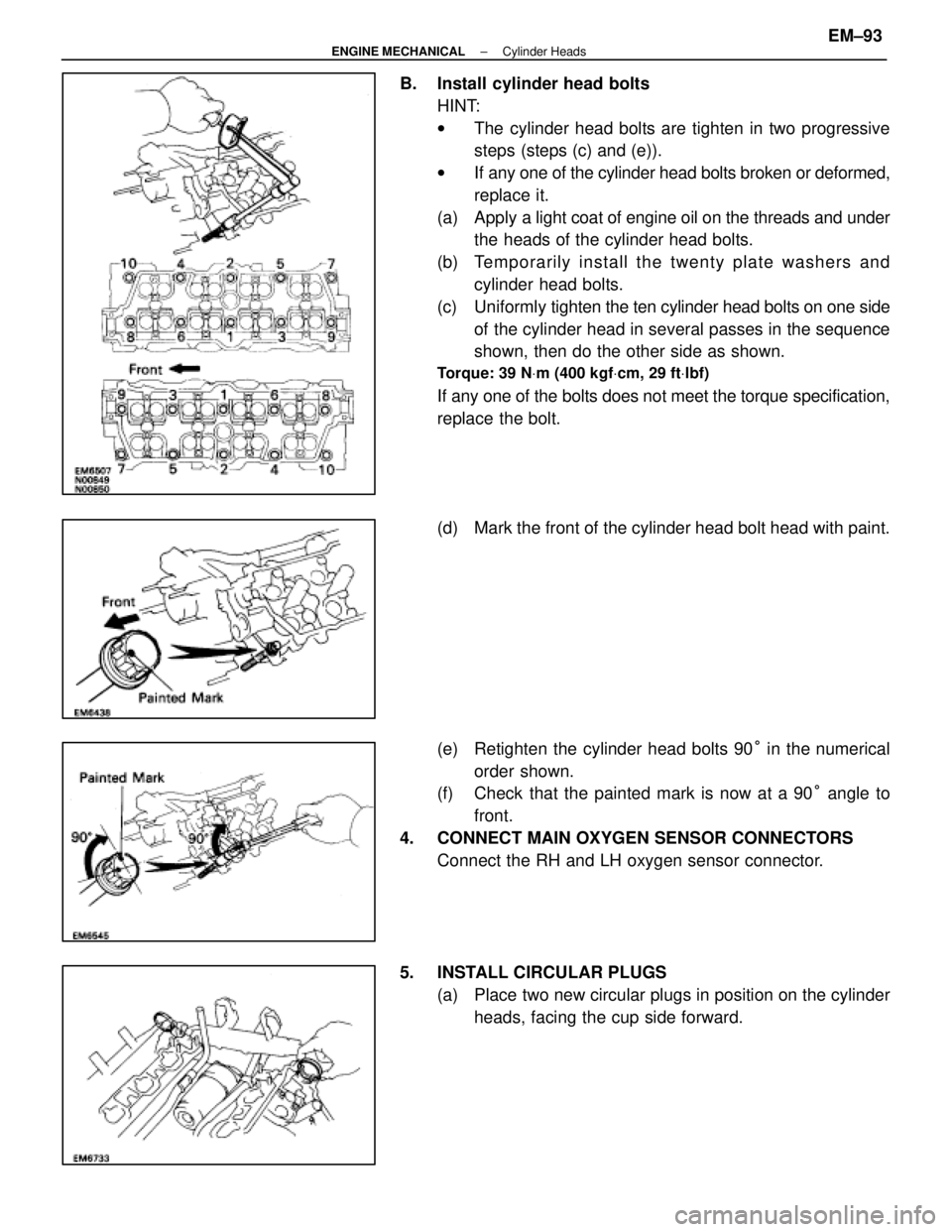
B. Install cylinder head boltsHINT:
wThe cylinder head bolts are tighten in two progressive
steps (steps (c) and (e)).
w If any one of the cylinder head bolts broken or deformed,
replace it.
(a) Apply a light coat of engine oil on the threads and under
the heads of the cylinder head bolts.
(b) Te mp o ra rily in sta ll th e twe n ty pla te wa sh e rs an d cylinder head bolts.
(c) Uniformly tighten the ten cylinder head bolts on one side
of the cylinder head in several passes in the sequence
shown, then do the other side as shown.
Torque: 39 N Vm (400 kgf Vcm, 29 ft Vlbf)
If any one of the bolts does not meet the torque specification,
replace the bolt.
(d) Mark the front of the cylinder head bolt head with paint.
(e) Retighten the cylinder head bolts 90 ° in the numerical
order shown.
(f) Check that the painted mark is now at a 90 ° angle to
front.
4. CONNECT MAIN OXYGEN SENSOR CONNECTORS Connect the RH and LH oxygen sensor connector.
5. INSTALL CIRCULAR PLUGS (a) Place two new circular plugs in position on the cylinderheads, facing the cup side forward.
±
ENGINE MECHANICAL Cylinder HeadsEM±93
WhereEverybodyKnowsYourName
Page 2297 of 4087
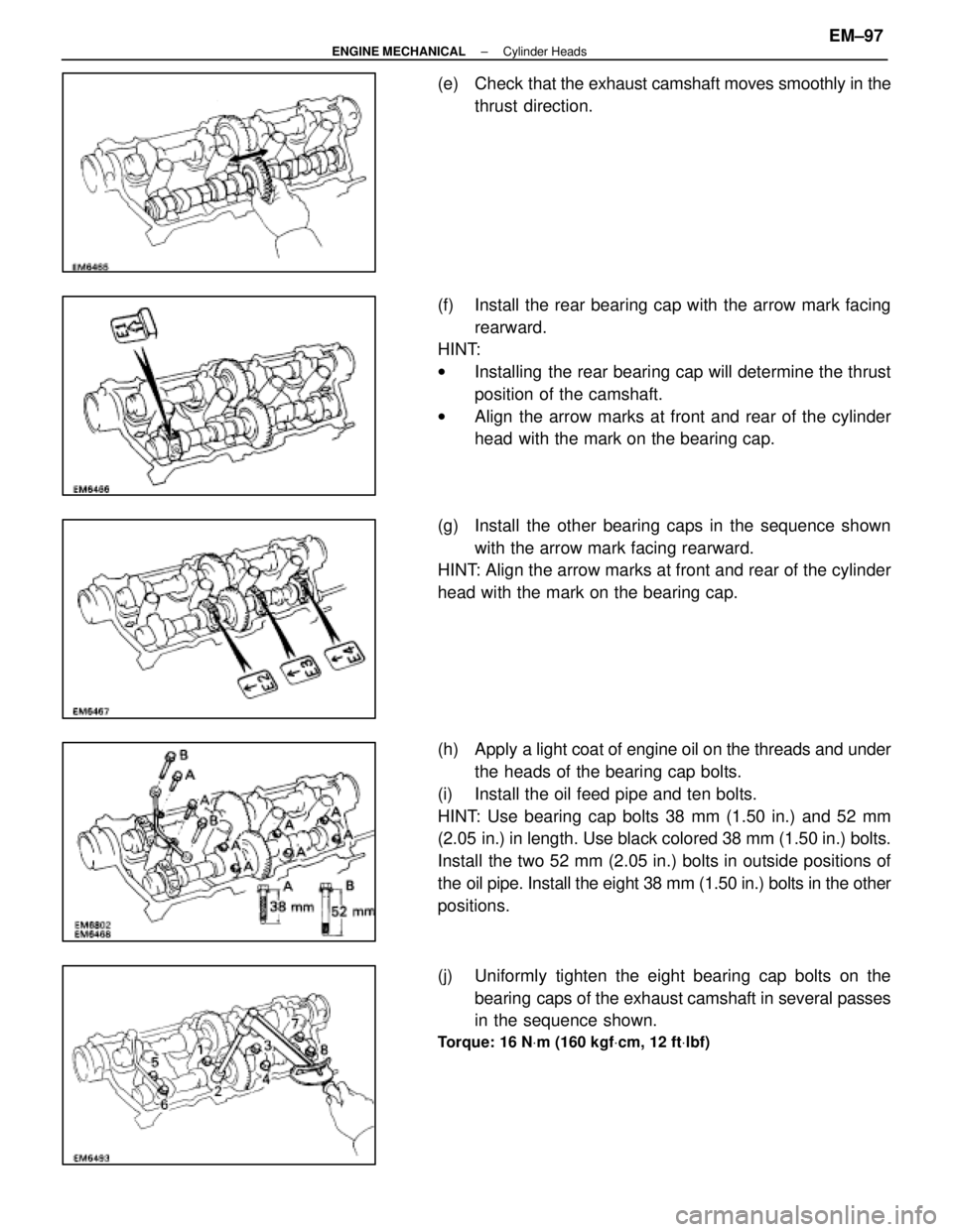
(e) Check that the exhaust camshaft moves smoothly in the
thrust direction.
(f) Install the rear bearing cap with the arrow mark facing rearward.
HINT:
w Installing the rear bearing cap will determine the thrust
position of the camshaft.
w Align the arrow marks at front and rear of the cylinder
head with the mark on the bearing cap.
(g) Install the other bearing caps in the sequence shown with the arrow mark facing rearward.
HINT: Align the arrow marks at front and rear of the cylinder
head with the mark on the bearing cap.
(h) Apply a light coat of engine oil on the threads and under
the heads of the bearing cap bolts.
(i) Install the oil feed pipe and ten bolts.
HINT: Use bearing cap bolts 38 mm (1.50 in.) and 52 mm
(2.05 in.) in length. Use black colored 38 mm (1.50 in.) bolts.
Install the two 52 mm (2.05 in.) bolts in outside positions of
the oil pipe. Install the eight 38 mm (1.50 in.) bolts in the other
positions.
(j) Uniformly tighten the eight bearing cap bolts on the bearing caps of the exhaust camshaft in several passes
in the sequence shown.
Torque: 16 N Vm (160 kgf Vcm, 12 ft Vlbf)
±
ENGINE MECHANICAL Cylinder HeadsEM±97
WhereEverybodyKnowsYourName
Page 2300 of 4087
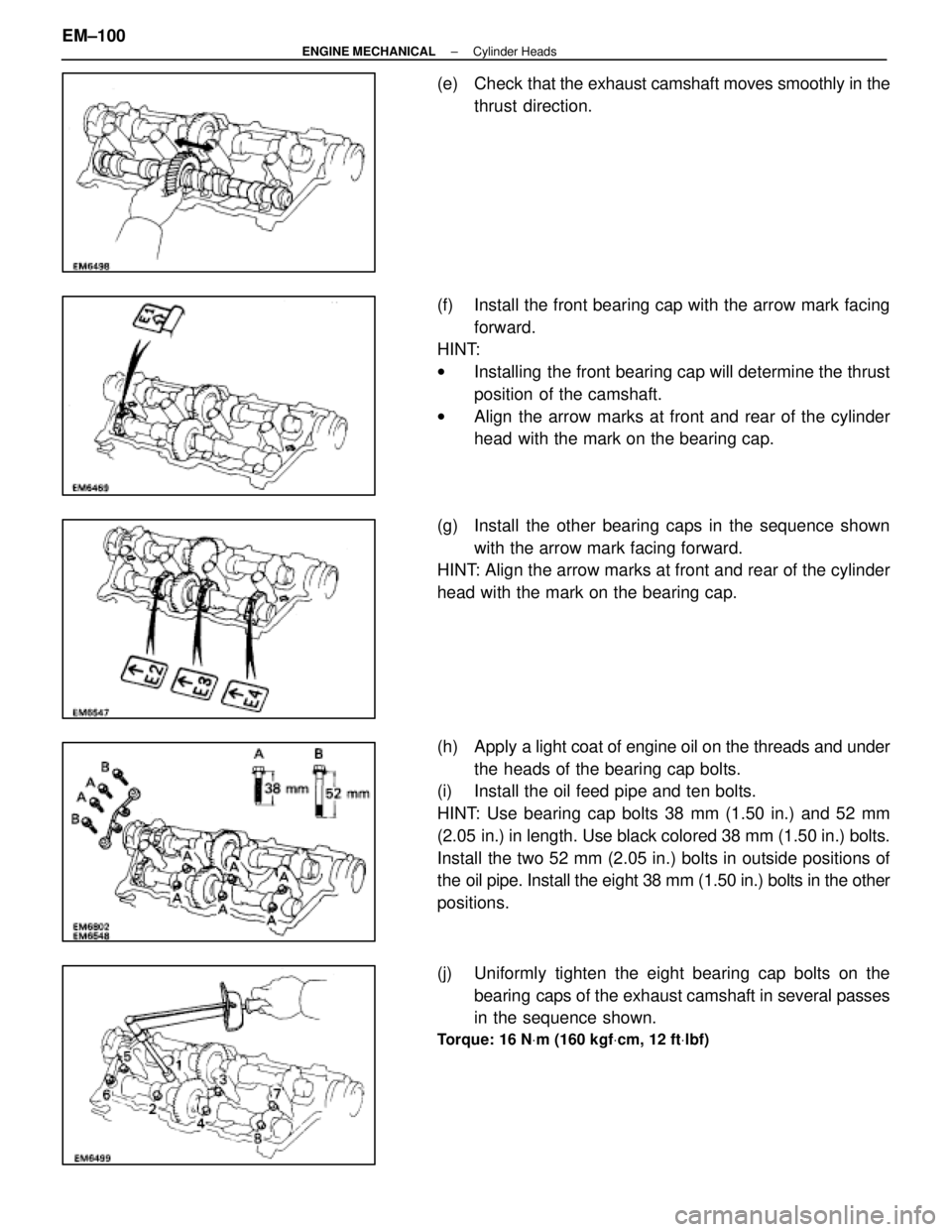
(e) Check that the exhaust camshaft moves smoothly in the
thrust direction.
(f) Install the front bearing cap with the arrow mark facing forward.
HINT:
w Installing the front bearing cap will determine the thrust
position of the camshaft.
w Align the arrow marks at front and rear of the cylinder
head with the mark on the bearing cap.
(g) Install the other bearing caps in the sequence shown with the arrow mark facing forward.
HINT: Align the arrow marks at front and rear of the cylinder
head with the mark on the bearing cap.
(h) Apply a light coat of engine oil on the threads and under
the heads of the bearing cap bolts.
(i) Install the oil feed pipe and ten bolts.
HINT: Use bearing cap bolts 38 mm (1.50 in.) and 52 mm
(2.05 in.) in length. Use black colored 38 mm (1.50 in.) bolts.
Install the two 52 mm (2.05 in.) bolts in outside positions of
the oil pipe. Install the eight 38 mm (1.50 in.) bolts in the other
positions.
(j) Uniformly tighten the eight bearing cap bolts on the
bearing caps of the exhaust camshaft in several passes
in the sequence shown.
Torque: 16 N Vm (160 kgf Vcm, 12 ft Vlbf)
EM±100±
ENGINE MECHANICAL Cylinder Heads
WhereEverybodyKnowsYourName