Page 2633 of 4087

FAIL±SAFE CHART
If any of the following codes is recorded, the ECU enters fail±
safe mode.
Code No.Fail±Safe OperationFail±Safe Deactivation Conditions
14Fuel cut1 IGF1 detected in consecutive 8 ignitions.
15Fuel cut1 IGF2 detected in consecutive 8 ignitions.
16Torque control prohibited.Returned to normal condition.
22THW is fixed at 805C (176 5F).Returned to normal condition.
24THA is fixed at 20 5C (68 5F).Returned to normal condition.
31
Ignition timing controlled between 10 5 ~ 30 5
BTDC,
Injection time controlled between 3 msec. ~ 30 m
sec., in relation to:
w Engine rpm
w Throttle angle
w ISC step value
KS input 15 times/sec. or more.
35Atmospheric pressure is fixed at 760 mmHg.Returned to normal condition.
The following 1 or 2 must be repeated at least 2
times consecutively.
41VTA1 is fixed at 051 When IDL is ON41VTA1 is fixed at 051 When IDL is ON
0.25 V � VTA1 � 0.95 V
2 When IDL is OFF2 When IDL is OFF
0.25 V � VTA1 � 4.9 V
The following 1 or 2 must be repeated at least 2
times consecutively.
47Value of VTA1 is used1 When IDL2 is ON47Value of VTA1 is used.1 When IDL2 is ON
0.25 V � VTA2 � 0.95 V
2 When IDL2 is OFF2 When IDL2 is OFF
0.25 V � VTA2 � 4.9 V
52Max. timeing retardation.IG switch OFF.
53Max. timeing retardation.Returned to normal condition.
55Max. timeing retardation.IG switch OFF.
Back±Up Function
If there is trouble with the program in the ECU and the ignition signals\
(IGT) are not output, the ECU controls
fuel injection and ignition timing at predetermined levels as a back±up f\
unction to make it possible to continue
to operate the vehicle.
Furthermore, the injection duration is calculated from the satrting sign\
al (STA) and the throttle position signal
(IDL). Also, the ignition timing is fixed at the initial ignition timing, 5 5 BTDC, without relation to the engine speed.
HINT: If the engine is controlled by the back±up function, the CHECK ENGIN\
E light lights up to warn the driver
of the malfunction but the diagnostic code is not output. TR±22
±
ENGINE TROUBLESHOOTING Fail±Safe Chart
WhereEverybodyKnowsYourName
Page 2634 of 4087
CHECK FOR MOMENTARY
INTERRUPTION
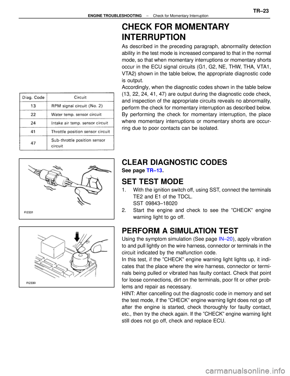
As described in the preceding paragraph, abnormality detection
ability in the test mode is increased compared to that in the normal
mode, so that when momentary interruptions or momentary shorts
occur in the ECU signal circuits (G1, G2, NE, THW, THA, VTA1,
VTA2) shown in the table below, the appropriate diagnostic code
is output.
Accordingly, when the diagnostic codes shown in the table below
(13, 22, 24, 41, 47) are output during the diagnostic code check,
and inspection of the appropriate circuits reveals no abnormality,
perform the check for momentary interruption as described below.
By performing the check for momentary interruption, the place
where momentary interruptions or momentary shorts are occur-
ring due to poor contacts can be isolated.
CLEAR DIAGNOSTIC CODES
See page TR±13.
SET TEST MODE
1. With the ignition switch off, using SST, connect the terminals
TE2 and E1 of the TDCL.
SST 09843±18020
2. Start the engine and check to see the ºCHECKº engine warning light to go off.
PERFORM A SIMULATION TEST
Using the symptom simulation (See page IN±20), apply vibration
to and pull lightly on the wire harness, connector or terminals in the
circuit indicated by the malfunction code.
In this test, if the ºCHECKº engine warning light lights up, it in\
di-
cates that the place where the wire harness, connector or termi-
nals being pulled or vibrated has faulty contact. Check that point
for loose connections, dirt on the terminals, poor fit or other prob-
lems and repair as necessary.
HINT: After cancelling out the diagnostic code in memory and set
the test mode, if the ºCHECKº engine warning light does not go off
after the engine is started, check thoroughly for faulty contact,
etc., then try the check again. If the ºCHECKº engine warning light
still does not go off, check and replace ECU.
±
ENGINE TROUBLESHOOTING Check for Momentary InterruptionTR±23
WhereEverybodyKnowsYourName
Page 2636 of 4087
OKNG
OKNG
5Check idle speed.
C
OK
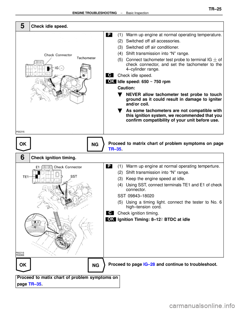
P(1) Warm up engine at normal operating temperature.
(2) Switched off all accessories.
(3) Switched off air conditioner.
(4) Shift transmission into ªNº range.
(5) Connect tachometer test probe to terminal IG � of
check connector, and set the tachometer to the
4±cylinder range.
Check idle speed.
Idle speed: 650 ~ 750 rpm
Caution:
�NEVER allow tachometer test probe to touch
ground as it could result in damage to igniter
and/or coil.
�As some tachometers are not compatible with
this ignition system, we recommended that you
confirm compatibility of your unit before use.
Proceed to matrix chart of problem symptoms on page
TR±35 .
6Check ignition timing.
C
OK
P(1) Warm up engine at normal operating temperture.
(2) Shift transmission into ªNº range.
(3) Keep the engine speed at idle.
(4) Using SST, connect terminals TE1 and E1 of check
connector.
SST 09843±18020
(5) Using a timing light. connect the tester to No. 6 high±tension cord.
Check ignition timing.
Ignition Timing: 8±12 � BTDC at idle
Proceed to page IG±28 and continue to troubleshoot.
Proceed to matix chart of problem symptoms on
page TR±35 .
±
ENGINE TROUBLESHOOTING Basic InspectionTR±25
WhereEverybodyKnowsYourName
Page 2674 of 4087
CIRCUIT DESCRIPTION (Cont'd)
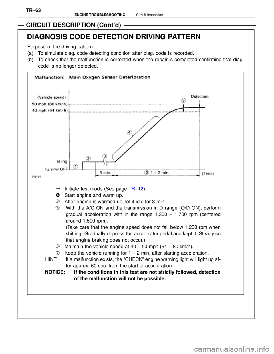
Purpose of the driving pattern.
(a) To simulate diag. code detecting condition after diag. code is recorded.
(b) To check that the malfunction is corrected when the repair is completed confirming that diag.code is no longer detected.
DIAGNOSIS CODE DETECTION DRIVING PATTERN
��Initiate test mode (See page TR±12).
��Start engine and warm up.
��After engine is warmed up, let it idle for 3 min.
�With the A/C ON and the transmission in D range (O/D ON), perform
gradual acceleration with in the range 1,300 ± 1,700 rpm (centered
around 1,500 rpm).
(Take care that the engine speed does not fall below 1,200 rpm when
shifting. Gradually depress the accelerator pedal and kept it. Steady so
that engine braking does not occur.)
��Maintain the vehicle speed at 40 ± 50 mph (64 ± 80 km/h).
��Keep the vehicle running for 1 ± 2 min. after starting acceleration.
HINT: If a malfunction exists, the ºCHECKº engine warning light will light\
up af-
ter approx. 60 sec. from the start of acceleration.
NOTICE: If the conditions in this test are not strictly followed, detection of the malfunction will not be possible.
TR±63
±
ENGINE TROUBLESHOOTING Circuit Inspection
WhereEverybodyKnowsYourName
Page 2686 of 4087
CIRCUIT DESCRIPTION (Cont'd)
DIAGNOSIS CODE DETECTION DRIVING PATTERN
Purpose of the driving pattern.
(a) To simulate diag. code detecting condition after diag. code is recorded.
(b) To check that the malfunction is corrected when the repair is completed c\
onfirming that diag. code is no longer detected.
Malfunction: Open or Short in Main Oxygen Sensor
�Initiate test mode (See page TR±12).
�Start engine and warm up.
�After engine is warmed up, let it idle for 3 min.
�Perform quick racing to 4,000 rpm three times by accelerator pedal.
�After performing the racing in (4), perform racing at 2,000 rpm for 90\
sec.
HINT: If a malfunction exists, the ºCHECKº engine warning light will light up after 90 sec. from the start of racing.
NOTICE: If the conditions in this test are not strictly followed, detection of t\
he malfunction will not be possible.
TR±75±
ENGINE TROUBLESHOOTING Circuit Inspection
WhereEverybodyKnowsYourName
Page 2687 of 4087
CIRCUIT DESCRIPTION (Cont'd)
DIAGNOSIS CODE DETECTION DRIVING PATTERN
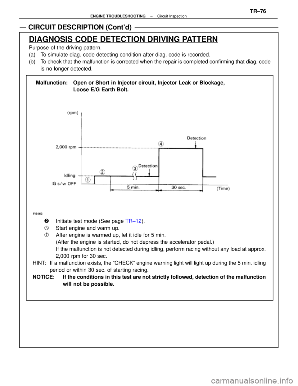
Purpose of the driving pattern.
(a) To simulate diag. code detecting condition after diag. code is recorded.
(b) To check that the malfunction is corrected when the repair is completed co\
nfirming that diag. codeis no longer detected.
Malfunction: Open or Short in Injector circuit, Injector Leak or Blockage, Loose E/G Earth Bolt.
�Initiate test mode (See page TR±12).
�Start engine and warm up.
�After engine is warmed up, let it idle for 5 min.
(After the engine is started, do not depress the accelerator pedal.)
\bIf the malfunction is not detected during idling, perform racing without a\
ny load at approx.
2,000 rpm for 30 sec.
HINT: If a malfunction exists, the ºCHECKº engine warning light will light up during the 5 min. idling
period or within 30 sec. of starting racing.
NOTICE: If the conditions in this test are not strictly followed, detection of the\
malfunction will not be possible.
±
ENGINE TROUBLESHOOTING Circuit InspectionTR±76
WhereEverybodyKnowsYourName
Page 2694 of 4087
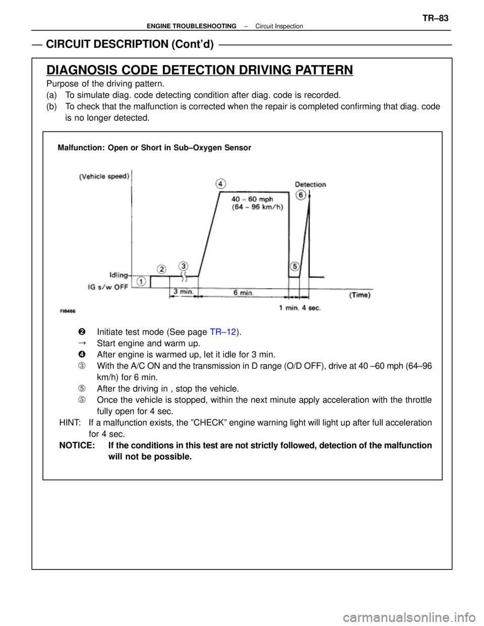
CIRCUIT DESCRIPTION (Cont'd)
DIAGNOSIS CODE DETECTION DRIVING PATTERN
Purpose of the driving pattern.
(a) To simulate diag. code detecting condition after diag. code is recorded.
(b) To check that the malfunction is corrected when the repair is completed co\
nfirming that diag. codeis no longer detected.
Malfunction: Open or Short in Sub±Oxygen Sensor
�Initiate test mode (See page TR±12).
�Start engine and warm up.
�After engine is warmed up, let it idle for 3 min.
�With the A/C ON and the transmission in D range (O/D OFF), drive at 40 ±\
60 mph (64±96
km/h) for 6 min.
�After the driving in , stop the vehicle.
�Once the vehicle is stopped, within the next minute apply acceleration w\
ith the throttle
fully open for 4 sec.
HINT: If a malfunction exists, the ºCHECKº engine warning light will light\
up after full acceleration for 4 sec.
NOTICE: If the conditions in this test are not strictly followed, detection of the\
malfunction will not be possible.
±
ENGINE TROUBLESHOOTING Circuit InspectionTR±83
WhereEverybodyKnowsYourName
Page 2712 of 4087
NGOK
OKNG
v
INSPECTION PROCEDURE
1Check output condition of diag. code 43.
C
OK
P
OK
C
Setting the test mode.
(2) Turn ignition switch OFF.
(2) Connect terminals TE2 and E1 of TDCL.
(2) Turn ignition switch ON.(Don't start the engine)
(2) Connect terminals TE1 and E1 of TDCL.
Check if code ª43º is output by the ªCHECKº engine
warning light.
Code ª43º is output.
Start the engine.
Check if the code ª43º disapears.
Code ª43º is not output.
Proceed to next circuit inspection shown on maxtric
chart (See page TR±35).
2Check for open in harness and connectors between engine & ECT ECU and st\
arter relay
(See page IN±27).
Repair or replace harness or connector.
Check and replace engine & ECT ECU.
±
ENGINE TROUBLESHOOTING Circuit InspectionTR±101
WhereEverybodyKnowsYourName