Page 2714 of 4087
CIRCUIT DESCRIPTION (Cont'd)
DIAGNOSIS CODE DETECTION DRIVING PATTERN
Purpose of the driving pattern.
(a) To simulate diag. code detecting condition after diag. code is recorded.
(b) To check that the malfunction is corrected when the repair is completed c\
onfirming that diag. code is nolonger detected.
Malfunction: Open or Short in Knock Sensor
�Start engine and warm up.
�After engine is warmed up, let it idle for 3 min.
�With the A/C ON, perform quick racing (5,000 rpm) three times.
(Rapidly depress the accelerator pedal and suddenly release it.)
HINT: If a malfunction exists, the ºCHECKº engine warning light will lig\
ht up when sudden racing is performed.
NOTICE: If the conditions in this test are not strictly followed, detection of t\
he malfunction will
not be possible.
±
ENGINE TROUBLESHOOTING Circuit InspectionTR±103
WhereEverybodyKnowsYourName
Page 2720 of 4087
CIRCUIT DESCRIPTION (Cont'd)
DIAGNOSIS CODE DETECTION DRIVING PATTERN
Purpose of the driving pattern.
(a) To simulate diag. code detecting condition after diag. code is recorded.
(b) To check that the malfunction is corrected when the repair is completed c\
onfirming that diag. code is nolonger detected.
�Initiate test mode (See page TR±12).
�Start engine and warm up.
�After engine is warmed up, let it idle for 3 min.
�With the A/C ON and transmission in D range (O/D OFF), drive at 40±\
70 mph for 4 min.
HINT: If a malfunction exists, the ºCHECKº engine warning light will light up at 1±4 min. of driving at 40±70 mph (64±112 km/h).
NOTICE: If the conditions in this test are not strictly followed, detection of the\
malfunction will not be possible.
Malfunction: Open in EGR gas temp. sensor circuit
±
ENGINE TROUBLESHOOTING Circuit InspectionTR±109
WhereEverybodyKnowsYourName
Page 2731 of 4087
OKNG
OKNG
INSPECTION PROCEDURE
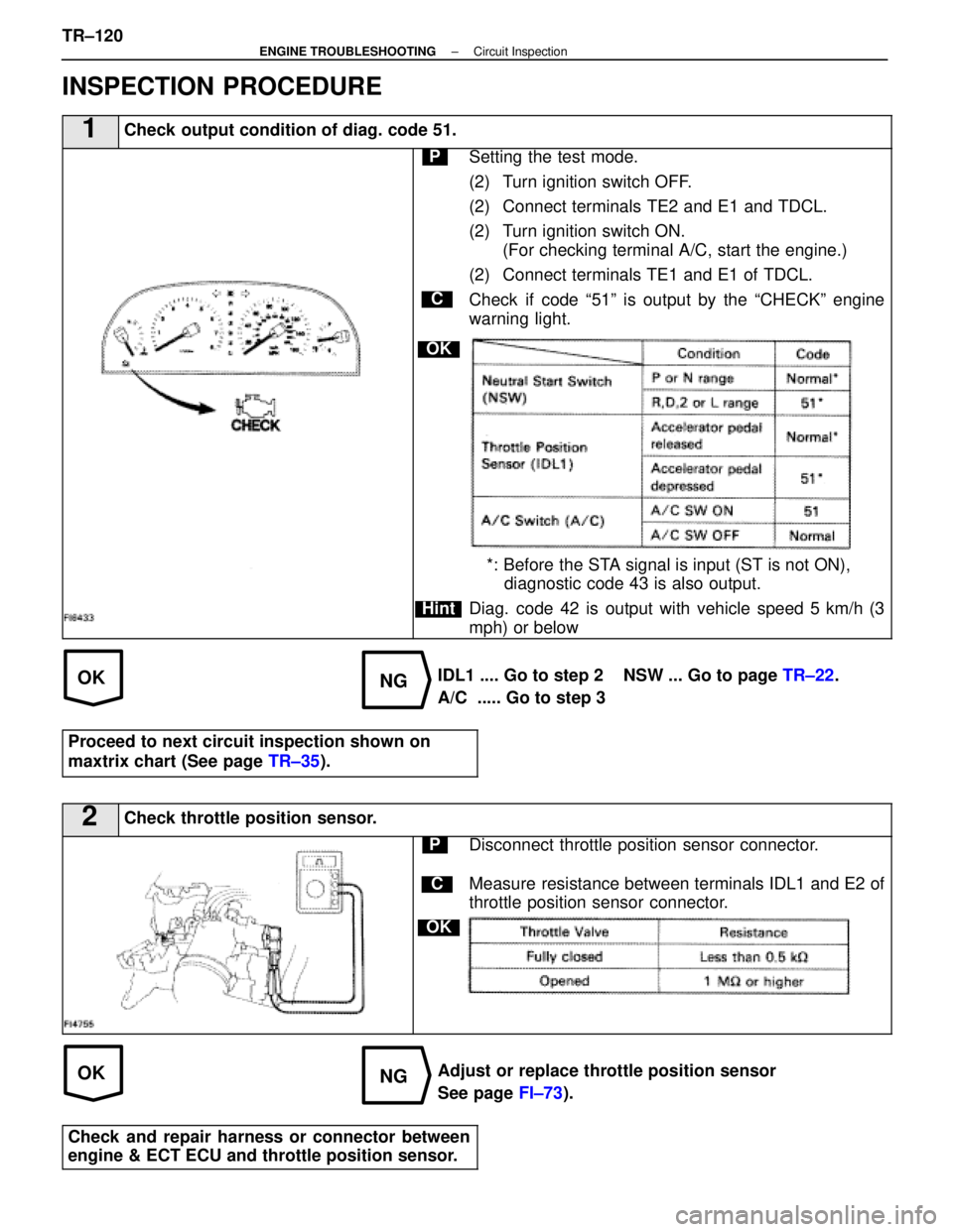
1Check output condition of diag. code 51.
C
OK
Hint
PSetting the test mode.
(2) Turn ignition switch OFF.
(2) Connect terminals TE2 and E1 and TDCL.
(2) Turn ignition switch ON.(For checking terminal A/C, start the engine.)
(2) Connect terminals TE1 and E1 of TDCL.
Check if code ª51º is output by the ªCHECKº engine
warning light.
*: Before the STA signal is input (ST is not ON), diagnostic code 43 is also output.
Diag. code 42 is output with vehicle speed 5 km/h (3
mph) or below
IDL1 .... Go to step 2 NSW ... Go to page TR±22.
A/C ..... Go to step 3
Proceed to next circuit inspection shown on
maxtrix chart (See page TR±35).
2Check throttle position sensor.
C
OK
PDisconnect throttle position sensor connector.
Measure resistance between terminals IDL1 and E2 of
throttle position sensor connector.
Adjust or replace throttle position sensor
See page FI±73).
Check and repair harness or connector between
engine & ECT ECU and throttle position sensor.
TR±120±
ENGINE TROUBLESHOOTING Circuit Inspection
WhereEverybodyKnowsYourName
Page 2757 of 4087
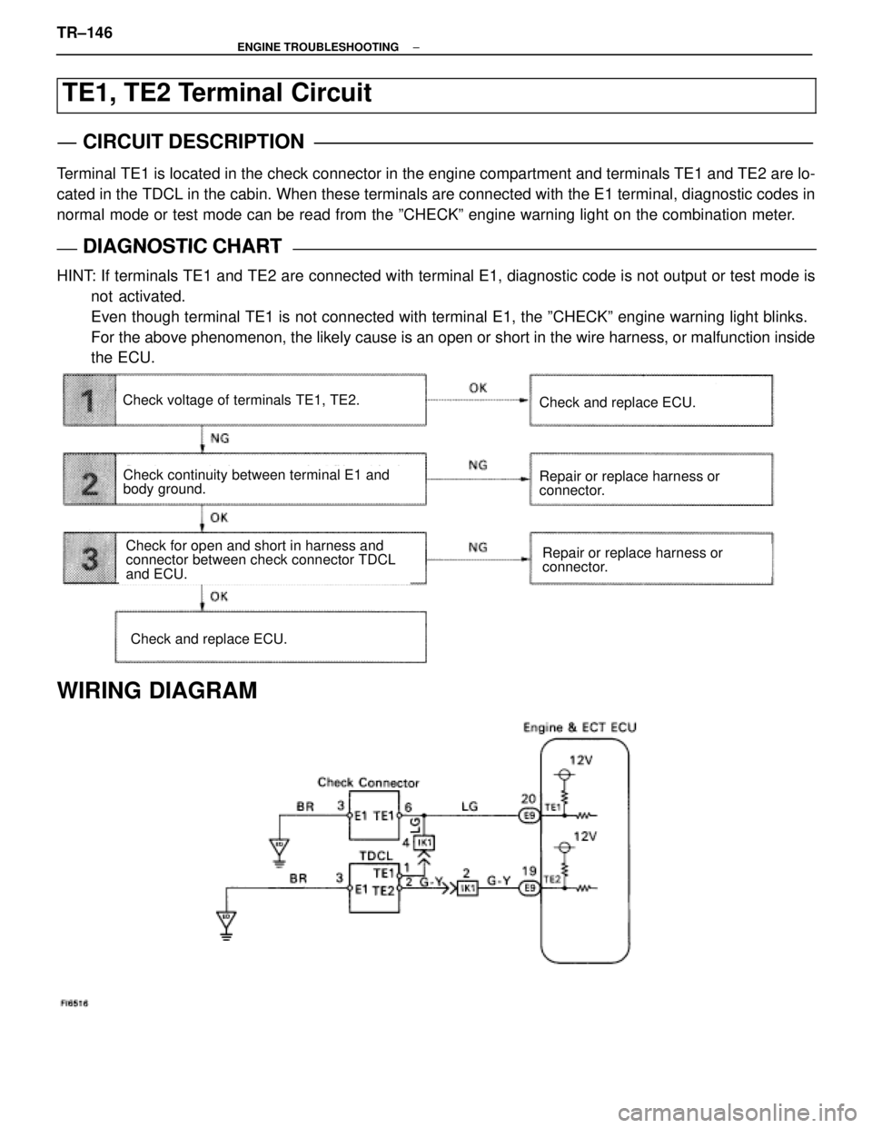
TE1, TE2 Terminal Circuit
CIRCUIT DESCRIPTION
Terminal TE1 is located in the check connector in the engine compartment and terminals T\
E1 and TE2 are lo-
cated in the TDCL in the cabin. When these terminals are connected with \
the E1 terminal, diagnostic codes in
normal mode or test mode can be read from the ºCHECKº engine warning lig\
ht on the combination meter.
DIAGNOSTIC CHARTDIAGNOSTIC CHART
HINT: If terminals TE1 and TE2 are connected with terminal E1, diagnostic code is not output or test mode isnot activated.
Even though terminal TE1 is not connected with terminal E1, the ºCHEC\
Kº engine warning light blinks.
For the above phenomenon, the likely cause is an open or short in the wire \
harness, or malfunction inside
the ECU.
Check continuity between terminal E1 and
body ground.
Repair or replace harness or
connector.Check for open and short in harness and
connector between check connector TDCL
and ECU.
Check voltage of terminals TE1, TE2.
Check and replace ECU.
Repair or replace harness or
connector.
Check and replace ECU.
WIRING DIAGRAM
TR±146±
ENGINE TROUBLESHOOTING
WhereEverybodyKnowsYourName
Page 2770 of 4087
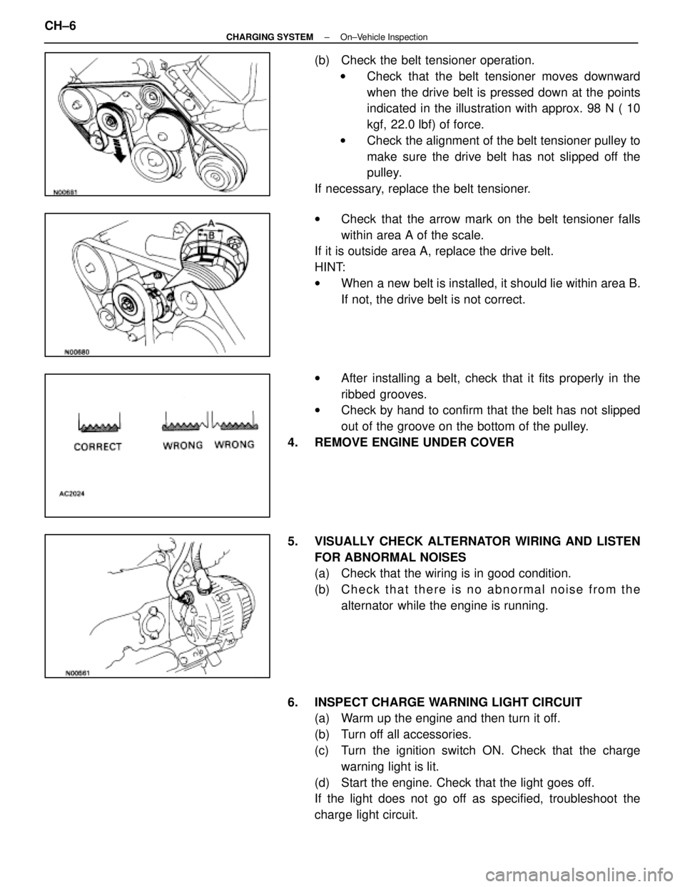
(b) Check the belt tensioner operation.w Check that the belt tensioner moves downward
when the drive belt is pressed down at the points
indicated in the illustration with approx. 98 N ( 10
kgf, 22.0 lbf) of force.
w Check the alignment of the belt tensioner pulley to
make sure the drive belt has not slipped off the
pulley.
If necessary, replace the belt tensioner.
w Check that the arrow mark on the belt tensioner falls
within area A of the scale.
If it is outside area A, replace the drive belt.
HINT:
w When a new belt is installed, it should lie within area B.
If not, the drive belt is not correct.
w After installing a belt, check that it fits properly in the
ribbed grooves.
w Check by hand to confirm that the belt has not slipped
out of the groove on the bottom of the pulley.
4. REMOVE ENGINE UNDER COVER
5. VISUALLY CHECK ALTERNATOR WIRING AND LISTEN FOR ABNORMAL NOISES
(a) Check that the wiring is in good condition.
(b) C h e c k t h a t t h e r e i s n o a bnormal noise from the
alternator while the engine is running.
6. INSPECT CHARGE WARNING LIGHT CIRCUIT (a) Warm up the engine and then turn it off.
(b) Turn off all accessories.
(c) Turn the ignition switch ON. Check that the charge
warning light is lit.
(d) Start the engine. Check that the light goes off.
If the light does not go off as specified, troubleshoot the
charge light circuit.
CH±6
±
CHARGING SYSTEM On±Vehicle Inspection
WhereEverybodyKnowsYourName
Page 2772 of 4087
8. INSPECT CHARGING CIRCUIT WITH LOAD(a) With the engine running at 2,000 rpm, turn on the highbeam headlights and place the heater blower switch at
ºHIº.
(b) Check the reading on the ammeter.
Standard amperage: 30 A or more
If the ammeter reading is less than standard amperage, re-
pair the alternator. (See page CH±9)
HINT: With the battery fully charged, the indication will some-
times be less than standard amperage.
9. REINSTALL ENGINE UNDER COVER
CH±8
±
CHARGING SYSTEM On±Vehicle Inspection
WhereEverybodyKnowsYourName
Page 2957 of 4087
OKNG
NGOK
NGOK
OKNG
INSPECTION PROCEDURE
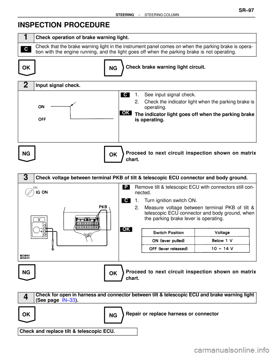
1Check operation of brake warning light.
Check that the brake warning light in the instrument panel comes on when the \
parking brake is opera-
tion with the engine running, and the light goes off when the parking brake is not operating.C
Check brake warning light circuit.
2Input signal check.
C
OK
1. See input signal check.
2. Check the indicator light when the parking brake isoperating.
The indicator light goes off when the parking brake
is operating.
Proceed to next circuit inspection shown on matrix
chart.
3Check voltage between terminal PKB of tilt & telescopic ECU connector and bod\
y ground.
C
OK
PRemove tilt & telescopic ECU with connectors still con-
nected.
1. Turn ignition switch ON.
2. Measure voltage between terminal PKB of tilt & telescopic ECU connector and body ground, when
the parking brake lever is operating.
Proceed to next circuit inspection shown on matrix
chart.
4Check for open in harness and connector between tilt & telescopic ECU and brak\
e warning light
(See page IN±33).
.
Repair or replace harness or connector
Check and replace tilt & telescopic ECU.
±
STEERING STEERING COLUMNSR±97
WhereEverybodyKnowsYourName
Page 3173 of 4087
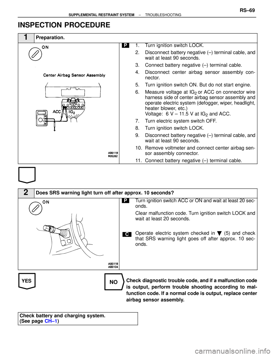
YESNO
INSPECTION PROCEDURE
1Preparation.
P1. Turn ignition switch LOCK.
2. Disconnect battery negative (±) terminal cable, andwait at least 90 seconds.
3. Connect battery negative (±) terminal cable.
4. Disconnect center airbag sensor assembly con- nector.
5. Turn ignition switch ON. But do not start engine.
6. Measure voltage at IG
2 or ACC on connector wire
harness side of center airbag sensor assembly and
operate electric system (defogger, wiper, headlight,
heater blower, etc.)
Voltage: 6 V ± 11.5 V at IG
2 and ACC.
7. Turn electric system switch OFF.
8. Turn ignition switch LOCK.
9. Disconnect battery negative (±) terminal cable, and wait at least 90 seconds.
10. Remove voltmeter and connect center airbag sen- sor assembly connector.
11. Connect battery negative (±) terminal cable.
2Does SRS warning light turn off after approx. 10 seconds?
C
PTurn ignition switch ACC or ON and wait at least 20 sec-
onds.
Clear malfunction code. Turn ignition switch LOCK and
wait at least 20 seconds.
Operate electric system checked in � (5) and check
that SRS warning light goes off after approx. 10 sec-
onds.
Check diagnostic trouble code, and if a malfunction code
is output, perform trouble shooting according to mal-
function code. If a normal code is output, replace center
airbag sensor assembly.
Check battery and charging system.
(See page CH±1)
±
SUPPLEMENTAL RESTRAINT SYSTEM TROUBLESHOOTINGRS±69
WhereEverybodyKnowsYourName